SMT,THT,PCB,PCBA,AI,wave soldering,reflow oven,nozzle,feeder,wave soldering

1 Video let you see what is auto insertion for electronic manufacturing Axial Component assembly

Axial Sequencer – The axial sequencer machine takes axial leaded through-hole components from reels and creates a tape chain of components in order of insertion for use on the axial insertion machine.


Component Lead Hole Guidelines

PCBs should be punched or drilled for component lead insertion to the following recommended hole diameters for optimum performance:

Hole Diameter = Lead Diameter + 0.48 mm (0.019 in.) ± 0.08 mm (0.003 in.)

Hole sizes:

• Less than recommended – Might result in reduced insertion reliability

• Greater than recommended – Might result in loose components in the PCB

Holes used for board error correction should be 1.0 mm (0.040 in.) ± 0.5 mm (0.020 in.). Plated holes or translucent PCBs might affect performance

SMT / THT /AI PRODUCTS – YOUR OWN CHOICE

SMT / THT /AI PRODUCTS – YOUR OWN CHOICE

WHY PEOPLE CHOOSE SOUTHERN MACHINERY PRODUCTS ?

1. High Productive and Everlasting Operative

Southern Machinery Products are Productive and long life operative. We design according to the New technology and fully automatic SMT Pick Place Machines, THT Machines according to the Clients requirements with in Short time delivery Period according to the specification of Clients with Affordable Price.

2.ADVANCED SOFTWARE

Compatible with all Electronic Design Automation software.

3.MULTILINGUAL

The software is 100% translated in Chines as well as in English.

4.COMPUTER VISION

Southern Machinery is using an advanced software that is using Computer Vision for calibration and when it is placing the electronic components.

5. VERY AFFORDABLE

Southern Machinery proves Total Solution for PCB – Professional solution of SMT/THT/AI, Provides Spare parts worldwide and Complete Training on site with affordable price. Where your ROI is 100 times of your investment.

6. VIDEO TUTORIALS

There will be plenty video tutorials to learn how to use Southern Machines to start assembling PCB s

7. EASY TO USE

The Southern Machines Products are easy to learn and Cool to use !

And many more qualities …………………

Southern Machinery Products – 2016 (New)

1.Automatic Loader SLD-400B
2.Automatic Unloader SULD-400B
3.Buffer Conveyor S-350C
4.Semi-Auto Screen Printer SP-1200
5.Automatic Screen Printer SP-1008
6.Pick & Place S-600-L
7.Pick & Place S-1200-LV
8.Pick & Place Machine S-320
9.LED High Speed Pick And Place S-K100
10.SCRAP TAPE CUTTER
11.Lead Free Reflow Oven S-6600
12.Lead Free Reflow Oven S-6600-PC
13.S1688 Pneumatic Stencil Cleaner Machine
14.S-DS300 Automatic dip soldering machine
15.S3000 Series- Radial Insertion Machine 16.S4000 Axial Auto Insertion Machine
17.S-7000I Odd Form Inserter
18.S-WS250 Wave Solder Machine
19.S-500S Auto-Dip Soldering machine
20.Automatic Spray Fluxing System
21.S8300 Shuttle conveyor -to merger production line 2 in 1
22.Solder Chip FEEDER
23.SMT Feeder Calibration jig
24.Desktop Pick & Place S-48V
25.Vibrating Feeder -for LED lens
26.Solder Paste Mixer
27.N2 Dry Cabinet

Auto Insertion Line

SMT Line

AI spare parts、Universal Parts,UIC,TDK.VCD Sequencer.SMT,THT,PCB,PCBA,AI,wave soldering,reflow oven,nozzle,feeder,wave soldering,PCB Assembly, LED, LED lamp, LED display

One Video let you know how Radial Insertion works for Electronic through-hole components assembly

  • Radial Insertion – A radial inserter takes radial leaded through-hole components from reels and creates a sequence of components in order of insertion. Then the machine auto inserts the components into the PCB. The machine can be programmed to bend and cut leads per customer/component specifications.


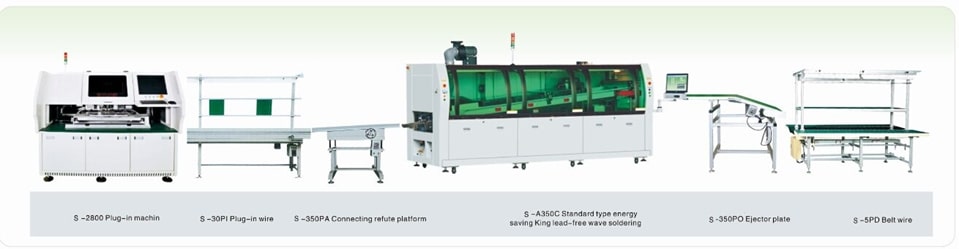
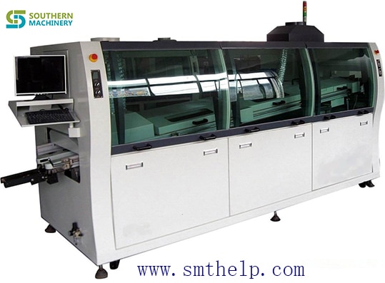
One Video show you how wave soldering machine work for electronic manufacturing PCBA


Southern machinery design and manufacturing wave solder machine, easy operation &maintenance, accurate temperature profile, flux saving,good soldering quality

  • Whole machine design is safe and reasonable, sensitive fault alarm system ensures the stability and safety


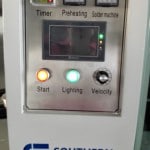
  • Time controller function, users can preset the on-off time , the heating up time of solder machine is 70 minutes.


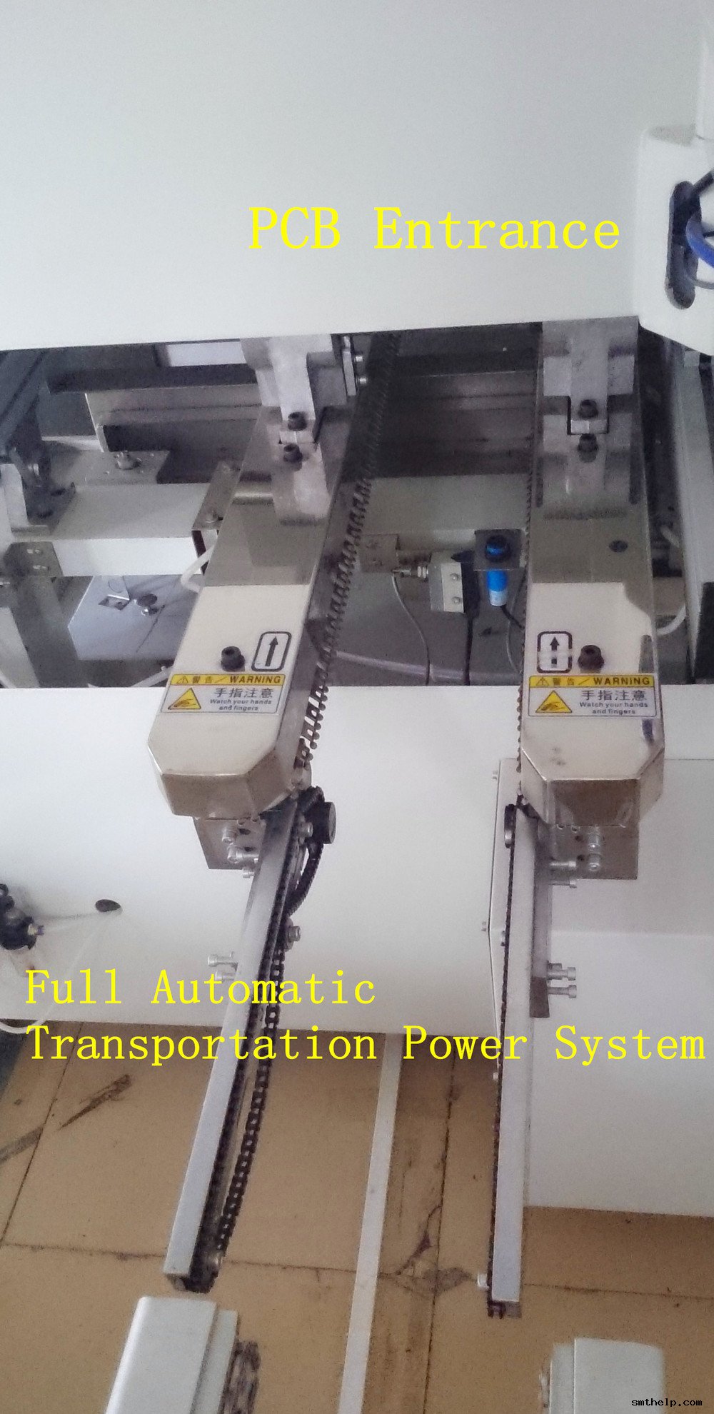
  • Full-automatic transport power system, stepless frequency speed adjustment, self-synchronous board entry


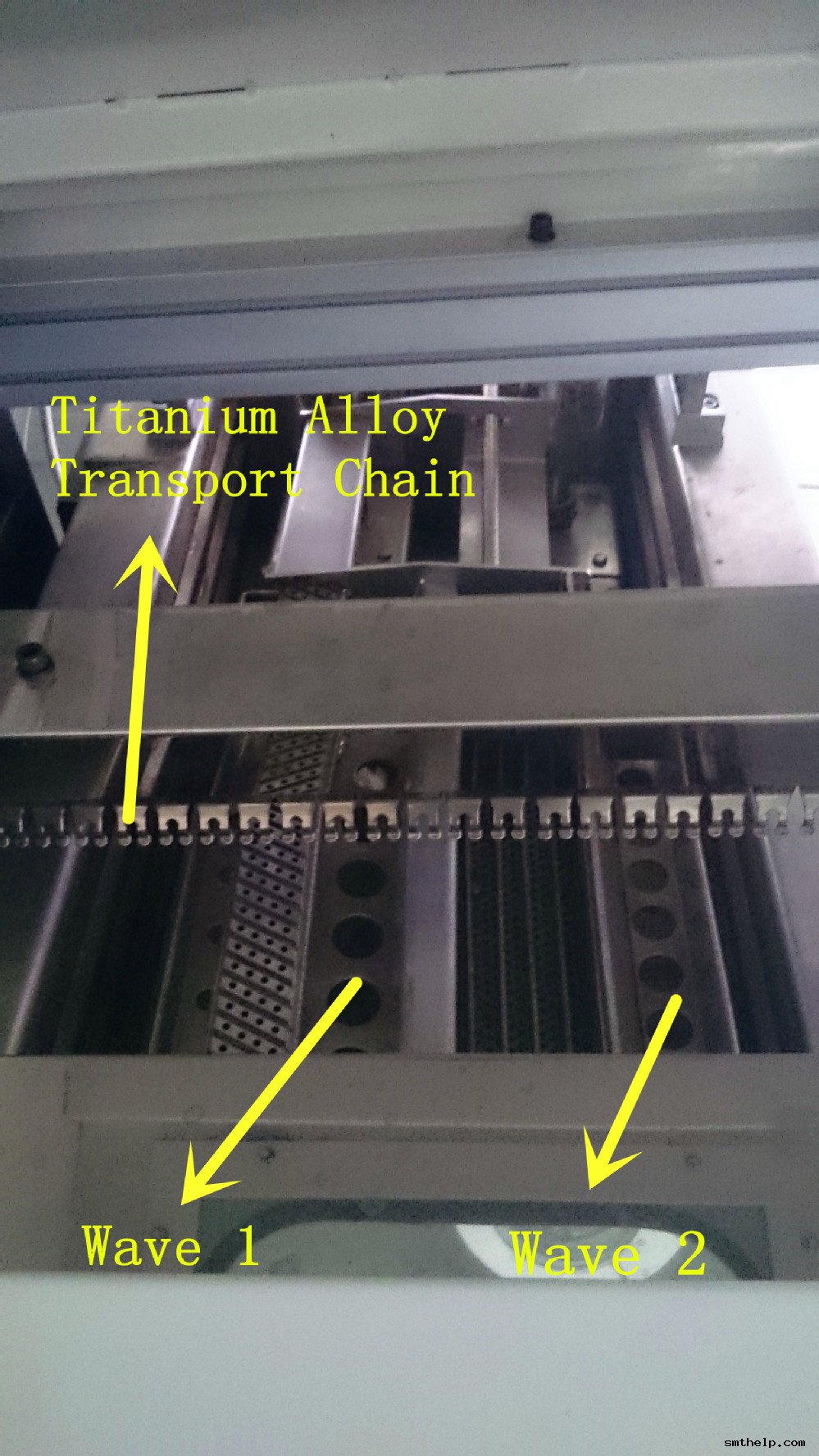
  • lTailor- made titanium alloy transport chain—1. Reinforced

—– 2. Non-tin-bonding          to guarantee the quality of welding


  • lAutomatic chain washing function to keep the cleanness of the chain


  • Preheating system adopts 3 sections strong hot air control system— 1.Quick in warming 2. Even temperature, ≤ ±2℃


  • lFlux spray system adopts the scanning spraying mode


  • lNissan Spray and rodess cylinder , PLC control, accurate and reliable


  • The solder machine adopts imported high temperature motor with steeless  frequency conversion control and independent control, stable welding performance.


  • lThe solder machine adopts lead free environmental friendly design, which is convenient and safe in going up/ down/ in/ out, easy to clean


  • lThe heating of the solder machine adopts hispeed PID external heated 2 phases independent control, which is quickly heating and solve the shortage of soldering.


Grandseed GSD-WD350T wave soldering machineGrandseed GSD-WD350T wave soldering machineGrandseed GSD-WD350T wave soldering machine

Grandseed GSD-WD350T wave soldering machine


One Video show you China Made LED chips SMT pick and place machine

2015 new designed LED light board pick and place assemble machine   :

Mounting head: Double arm, 36 pieces sucking mouth, 18 pieces sucking mouth per arm

Min mounting distance: 13.5mm

Driving motor of mounting head(Y axis): Principle motor(magnetic), 15% faster than servo screw motor

Mounting range: 0805,1206,2121,2835,3014,3528,5050,5630,5730,RGB and other LED belt light

Theory mounting speed: 70K CPH*2=140K CPH

Working mounting speed: 60K CPH*2=120K CPH

PCB sizes:1200MM(L)-300MM(W)

Feeder amount: 18 feeder(8mm)*2=36 feeders,electronic feeder

Vibrating disc, for bulk material: Can be customized, vibrating disc can be changed with FEEDER, and the

working speed is the same

Dimension(L*W*H): 2650*1650*1350mm

Total weight: 2000kg

Application: 0.3-1.2 meter LED daylight tube and soft light belt include RGB strip light, LED panel light etc


Model Pick and place speed Overall sizes( L*W*H) Weight
S-K100 Belt LED SMD 120K CPH 2650*1650*1350mm 2000kg
S-K200 Belt LED SMD 180K CPH 2650*1750*1400mm 2500kg
S-K100VP Bulk LED SMD 80K CPH 2650*1650*1350mm 2000kg
Detailed Images

Fully automatic electric feeder, can set the feeding design according to your mounting needs through the computer:

The highest capacity LED light board pick and place assemble machine


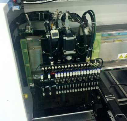
Double module mounting head, each module has 16 pieces sucking head:

The highest capacity LED light board pick and place assemble machine


South Korea magnetic motor, guarantee high mounting speed, easy to maintain:

The highest capacity LED light board pick and place assemble machine


Top performance industry computer, can be folded into the machine, easy to set placing design:

The highest capacity LED light board pick and place assemble machine


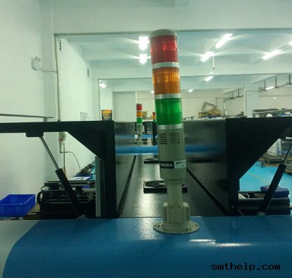
Skoda alarm, let you know the pick and place machines working condition clearly:

The highest capacity LED light board pick and place assemble machine


AI spare parts、Universal Parts,UIC,TDK.VCD Sequencer.SMT,THT,PCB,PCBA,AI,wave soldering,reflow oven,nozzle,feeder,wave soldering,PCB Assembly, LED, LED lamp, LED display

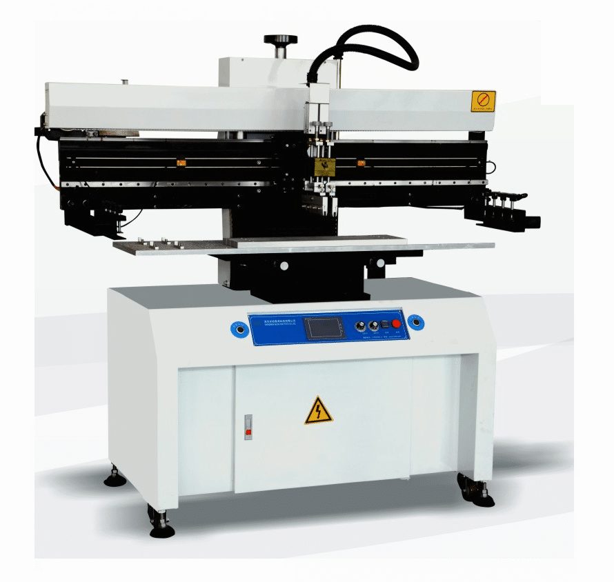
One Video tell you how SMT solder paste Semi-Auto Screen Printer work

A Solder Paste Screen Printer for SMT is needed to screen solder paste onto the printed circuit board (PCB) before placement of surface mount components.

Solder Paste Screen Printer for SMT have been widely used in electronics by the PCB industry for screen solder mask. This equipment / machine has also been extensively used in the hybrid industry for screening solder paste. However, different equipment is used for the screening of solder mask and solder paste. The cost of screen printers can vary widely, depending on their degree of automation and the size of boards they can handle.

Solder Paste Printing Systems are available in three configurations: manual, semi-automatic and fully automatic. The machine can be table mounted, stand-alone, or in-line. Many semi-automatic printers offer manual vision alignment capability, while fully automatic printers offer automatic vision alignment.

Soldering paste screen printer (25) AI spare parts、Universal Parts,UIC,TDK.VCD Sequencer.SMT,THT,PCB,PCBA,AI,wave soldering,reflow oven,nozzle,feeder,wave soldering,PCB Assembly, LED, LED lamp, LED display AI spare parts、Universal Parts,UIC,TDK.VCD Sequencer.SMT,THT,PCB,PCBA,AI,wave soldering,reflow oven,nozzle,feeder,wave soldering,PCB Assembly, LED, LED lamp, LED display

Soldering paste screen printer (25) AI spare parts、Universal Parts,UIC,TDK.VCD Sequencer.SMT,THT,PCB,PCBA,AI,wave soldering,reflow oven,nozzle,feeder,wave soldering,PCB Assembly, LED, LED lamp, LED display AI spare parts、Universal Parts,UIC,TDK.VCD Sequencer.SMT,THT,PCB,PCBA,AI,wave soldering,reflow oven,nozzle,feeder,wave soldering,PCB Assembly, LED, LED lamp, LED display

AI spare parts、Universal Parts,UIC,TDK.VCD Sequencer.SMT,THT,PCB,PCBA,AI,wave soldering,reflow oven,nozzle,feeder,wave soldering,PCB Assembly, LED, LED lamp, LED display

One Video show you how to auto insertion Odd form Component for Electronic manufacturing

PCBA Auto Insertion  – Axial, DIP, Radial, Pin, Odd-Form

We design and manufacture Odd Form component auto insertion machine,SMT equipment, and providing spare parts service. Worldwide Installation and on site support and training.

The primary sources for (new) automated through hole component insertion or through hole component assembly equipment today, are: Contact Systems, Fuji, Panasonic, TDK and Universal Instruments. All (5) OEMs have contributed to the advancements in equipment and technology that we use today to assemble printed circuit boards, and all provide spare parts and varying levels of technical support.


Contact System’s semi-automatic component insertion systems are capable of processing a wide range of components, including: axial, radial, dip, sip and even many odd-form devices. Although Contact’s machine are most commonly used to augment fully automatic assembly processes, it is not unusual to see the Contact Systems CS 400D and CS 400E component locators being used as the primary means of assembling printed circuit boards at many low to moderate volume manufacturing facilities. All CS 400 systems are ergonomically designed to minimize operator fatigue and maximize productivity by combining a convenient operator to machine interface with several types of parts delivery systems, including their: CS 210 Rotary Bin, CS 400LPD – Large Parts Dispenser, CS 241 Lighted DIP Dispenser and the CS 740 JIT Component Delivery Systems which are available in single ( CS 740BS ) and double picker ( CS 740BD ) configurations.

Contact System’s Ultra Clinch offers the unique feature of allowing the user to program lead lengths and clinch angles for each and every component being assembled.

Component insertion rates of 600 pph to 1,500 pph are typical.

Universal Instruments Corporation manufactures a complete line of through hole insertion equipment. Also known as Insertion Mounted Component ( IMC ) and pin in hole assembly equipment, UIC offers automatic component insertion platforms for: Axial, DIP, Pin, Radial, SIP, LED, Transistor and Odd-form devices.

Universal’s IMC line of axial component processing equipment includes:

Axial component sequencers that are available in the following models: 2596R, 2596A, 2596B, 2596C and 2596D. The expandable axial sequencers can be configured with: 20 to 220 stations using (20) station add-on modules, expanded range verifiers (ERV), refire, pass-thru or single board transfer – SBT . The typical yield rate of a Universal sequencer ranges from 12,000 pph to 25,000 pph.

To compliment the 2596 sequencer, Universal offers the following axial component insertion systems: 6285, 6287, 6287A, 6287B, Generation 8, VCD single head 8 and model 6295 dual head VCD. Other VCD based inserters include the Jumper wire single head 8 and Jumper wire dual head 8. The cycle rates of these machines range from 8,500 pph to 40,000 pph depending on their configuration and vintage. Aside from cycle rates their operating parameters are similar.

As an alternative to stand alone equipment, Universal also offers a combined sequencer/inserter for axial leaded devices. Referred to as: 6241, 6241A, 6241B, 6241C, 6241D, 6248/48F, VCD Sequencer 8 Inserter, these axial lead sequencer / inserters can be configured with the same features as stand alone equipment.

Universal’s DIP Inserter product line include: Uni-module, Multi-module and SIP platforms. Available options include: 4 Pin DIP LED Tooling, DIP/Socket tooling, Autostick, and Single Board Transfer. The single head Uni-mod or model 6796 will typically yield 2,500 pph to 3,200 pph. The dual head Multi-mod or model 6772 typically yields 3,400 pph to 4,200 pph.

Universal’s Radial Sequencer/Inserter product line inserts radially taped and reeled components with body diameters up to 13mm and lead spans of 2.5/5mm at speeds ranging from 6,500 pph to 11,000 pph. Often referred to as Rad 1, Rad 2, Rad 3, Rad 5 and Rad 8 machines, these platforms can be configured with: 20 to 80 stations, single board transfer – SBT and expanded range verifiers – ERV. Model numbers associated with the Radial products include: 6346, 6348, 6358, 6360 and 6380.

Fuji, Panasonic Factory Automation and TDK offer competitive products, including: Fuji’s Flexible Board Assembler – FBA, Panasonic’s RH & AV and TDK’s RH.


AI spare parts、Universal Parts,UIC,TDK.VCD Sequencer.SMT,THT,PCB,PCBA,AI,wave soldering,reflow oven,nozzle,feeder,wave soldering,PCB Assembly, LED, LED lamp, LED display AI spare parts、Universal Parts,UIC,TDK.VCD Sequencer.SMT,THT,PCB,PCBA,AI,wave soldering,reflow oven,nozzle,feeder,wave soldering,PCB Assembly, LED, LED lamp, LED display AI spare parts、Universal Parts,UIC,TDK.VCD Sequencer.SMT,THT,PCB,PCBA,AI,wave soldering,reflow oven,nozzle,feeder,wave soldering,PCB Assembly, LED, LED lamp, LED display AI spare parts、Universal Parts,UIC,TDK.VCD Sequencer.SMT,THT,PCB,PCBA,AI,wave soldering,reflow oven,nozzle,feeder,wave soldering,PCB Assembly, LED, LED lamp, LED display

AI spare parts、Universal Parts,UIC,TDK.VCD Sequencer.SMT,THT,PCB,PCBA,AI,wave soldering,reflow oven,nozzle,feeder,wave soldering,PCB Assembly, LED, LED lamp, LED display

S-ws250 Wave soldering machine for electronic manufacturing PCBA

Lead-free or Tin-lead Through-hole Soldering

adjustable dual waves permit lead-free or tin/lead processing of through-hole and SMD boards to a maximum width of 250 mm

As PCBs are loaded onto the adjustable titanium finger conveyor, they are automatically prepped by an adjustable internal spray fluxing system which houses a precision spray nozzle assembly mounted to a reciprocating Y-axis drive mechanism to ensure even and accurate application of flux.

Run as Dual or Single Wave

Solder processing temperature is settable to a lead-free compatible 300°C. The system includes an economical low-volume 200 kg (550 lbs. Approximate weight for lead free solder) capacity solder pot with an easy-handling roll-out feature. A built-in alarm signals when solder level is at the refill point.

Forced Hot Air Convection Pre-Heat

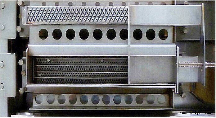
The preheat stage takes place in a 600 mm (23.6″) glass-covered chamber where boards are heat-bathed by energy-saving forced hot air convection, as opposed to power-consuming, uneven IR heat.

AI spare parts、Universal Parts,UIC,TDK.VCD Sequencer.SMT,THT,PCB,PCBA,AI,wave soldering,reflow oven,nozzle,feeder,wave soldering,PCB Assembly, LED, LED lamp, LED display


Automatic spray fluxer produces uniform fine spray coverage of underside of each incoming board. Integrated cooling zone provides rapid cooling for processed boards prior to exiting the conveyor.
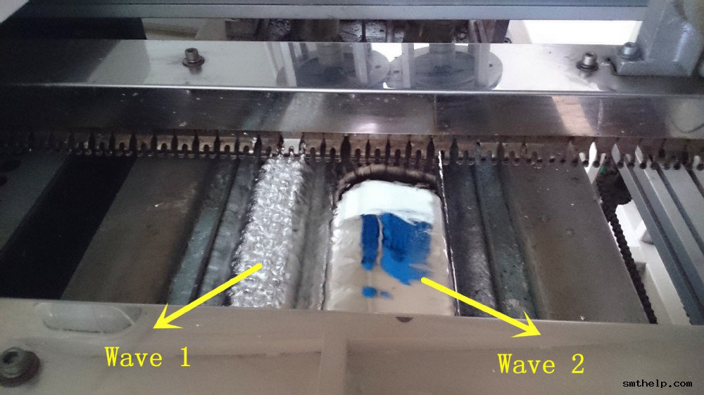
Energy-conserving 600 mm (23.6”) forced hot air convection preheater safely preps boards for higher temperatures of lead-free or tin-lead soldering while ensuring that fluxes are properly activated. Process area—where dual waves are generated by titanium alloy wave nozzles.
Preheat area remains enclosed under glass during processing, preventing escape of hot air. With front panel removed, dual solder pumps (top) and solder pot below are exposed. Electrical panel is accessed by removing cabinet door on right side.
Cooling fans apply focused below-board heat to quickly lower temperatures of processed boards. Titanium-alloy wave nozzle and components resist corrosion. Finger conveyors are automatically cleaned prior to loading of each board.
Titanium finger conveyor is hand-crank adjustable to boards of up to 350 mm width. Titanium finger conveyor is hand-crank adjustable to boards up to 350 mm width. Fingers are self cleaning.
Built-in flux fume exhaust hood and filter. Flux vapors are extracted through a built-in fume hood and filter, and out of the system through an exhaust flange on the top of the unit. The filter is easily removable for cleaning. A tote case containing all hand tools necessary for maintenance, repair or disassembly

Universal Auto Insertion Machine Axial Inserter ^241F PC BOARD FUNCTIONAL/TEST SPECIFICATION

PC BOARD FUNCTIONAL/TEST SPECIFICATION

DESCRIPTION OF ASSEMBLY PCA, SEQ MMIT I/O

PART NUMBER OF ASSEMBLY 47634502, -03, -04

PRODUCT CODE(S) 6241F

RELEASE NUMBER 66764/1018294

RELEASE DATE 4/15/10 (Updated 2/24/10)

  1. product description overview
  1. introduction

The Sequencer MMIT I/O Assy replaces the sequencer I/O box, the Optical Refire controllers, and the 20 AC Out PCBs with a single I/O card that interfaces to the Mini-MIT bus that has been used on the SMT Platform since its inception. The card has 20 DC outputs capable of driving up to 1 amp each at 12 VDC. The card has 40 inputs that are nominally dedicated for low parts and parts missing for the dispensing heads. In addition, the card has a diagnostic port which is not connected to any outputs and 8 general purpose inputs and outputs for other features such as start and stop switches.

  1. history

This card is a new design, but based on experience with Mini-MIT on the platform. The functions of this I/O card are the same as those of the modules it replaces (refire controller, 20 AC Output).

  1. physical description

The card is the same size as the 20 AC Output (5”x15”). The construction is a multi-layer surface mount assembly. To streamline manufacture, as many of the components as possible are surface mount.

  1. Compatibility

This card is designed to completely replace the previous control scheme. The only compatibility to existing equipment is for the dispensing heads and the jumper wire feeder. This card will support the new (stepper controlled) or old feeder. The cabling to the jumper wire feeder, however, is different. This card will not support the older AC valves or the old Refire Det PCBs. DC valves are required and the new Refire Det PCA is needed.

  1. operating features

The Seq MMIT I/O PCA an I/O card optimized for use on the IM sequencers. It has separate connectors for Mini-MIT in and out, and has separate connectors for each of the functions supported. In this way, the cabling can be modular, avoiding massive cable harnesses. All signals are routed through the gate array, which is programmable. Thus, the card’s function can be tailored to suit many diverse needs. The card is designed for low power consumption which reduces the cost of cables and eliminates any thermal problems. All signals going off board are conditioned to protect the board from damage from accidental wiring errors.

  1. operating specifications
  1. electrical power requirements

ï +12 VDC @ 4 A max.

ï +5 VDC @ 2 A max.

ï 24 VAC @ 2.5 A max.

Over current protection for the main +12 VDC and +5 VDC are provided by the power supply. The power supply should not be replaced without due consideration to the over current protection.

  1. Thermal considerations

There are no reasons for concern for any expected thermal conditions in the environment that it will be used in.

  1. inputs

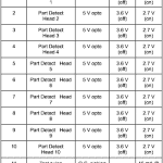
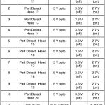
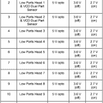
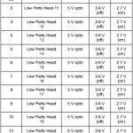
There are 48 inputs that are optically isolated and filtered. These are used for (20) part missing, (20) low parts and (8) general purpose inputs.

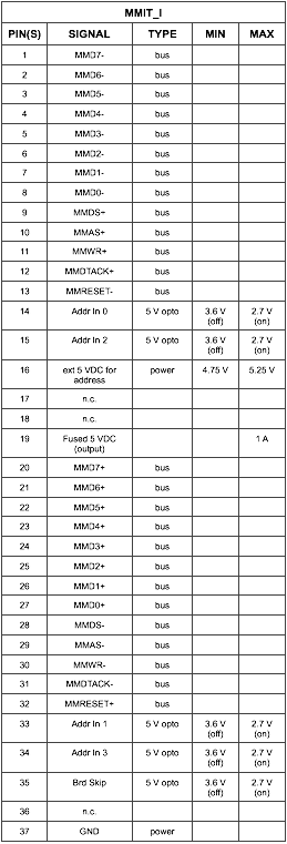
  • 5 V OPTO: Inputs are optically isolated with noise rejection. The input signals are referenced to the local +5 VDC supply. The inputs must be pulled below 2.7 VDC (2.3 VDC across the input) to activate the input. To guarantee the inactive state, the input must be above 3.6 VDC. There is a 0.01?F filtering capacitor across the opto-coupler to filter out high frequency noise. In addition, there is debouncing in the gate array to weed out signals shorter than approximately 50 ?s.
  • 12 V OPTO: Inputs are optically isolated with noise rejection. The input signals are referenced to the local +5 VDC supply. The inputs must be pulled below 9.2 VDC (2.8 VDC across the input) to activate the input. To guarantee the inactive state, the input must be above 10.3 VDC. There is a 0.01?F filtering capacitor across the opto-coupler to filter out high frequency noise. In addition, there is debouncing in the gate array to weed out signals shorter than approximately 50 ?s.
  • 24 VAC OPTO: There is one input referenced to 24 VAC for the TEST input from the jumper wire feeder. This input is diode blocked to provide a pulsing signal. There is one pulse per AC cycle. The input pulses are stretched in the gate array to approximately 27 ms. The input line must be pulled below 12 VACrms to guarantee an active signal and must be above 18 VACrms to guarantee an inactive state.
  • TTL INPUT: This is used only for a jumper in the plug that connects to this board to indicate that it is plugged in. This signal does not go off board any distance.
  1. outputs

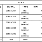
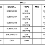
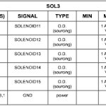
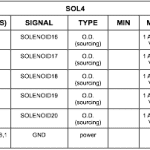
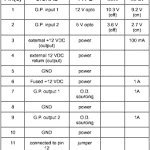
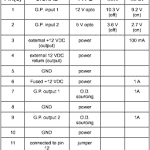
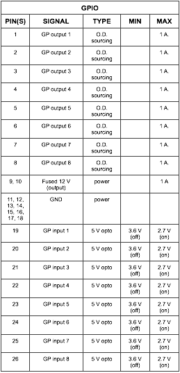
There are (20) 12 VDC sourcing outputs for valve solenoids. Each is capable of driving up to 1 A. There are 8 general purpose outputs that are also 12 VDC sourcing. In addition, 5 of these general purpose outputs also have AC relays on them capable of sourcing 24 VAC at up to 1 A.

  • O.D. SOURCING: Open drain MOSFET output referenced to the local +12 VDC supply. They are capable of sourcing 1 A each. The total limit of the 12 V supply is 4 A.
  • 24 VAC SOURCING: Triac output supplies 24 VAC at a maximum of 1 A.
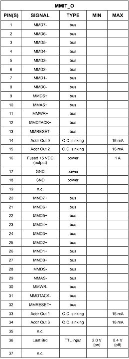
  • O.C. Sinking: Open collector TTL output (7407) referenced to the 5 VDC return (GND). These outputs are used for data links to adjacent boards.
  1. connector pin out

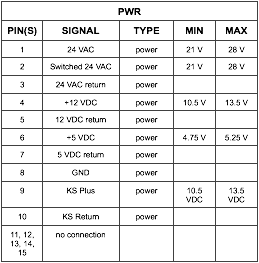
Power Input: 15 pin AMP Mate-n-lok connector that supplies +12 VDC, return, +5 VDC, return, 24 VAC, switched 24 VAC, and return, and an external power source.
Jumper Wire Feeder: 6 pin AMP Mate-n-lok connector that supplies 24 VAC, return, the DC output for head 3 and the Out of Wire input for head 3. The output and input are in parallel with the output and input for the dispensing head itself. In addition, there is a Test input from the jumper wire feeder that will manually feed a wire and fire the dispensing head.
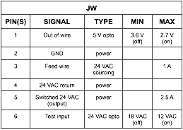
Valve Drivers: (4) 10 pin Mod-U connectors supplying 5 sourcing signal lines and 5 return lines. These outputs are open drain P-channel MOSFETs.

Part Missing: (2) 15 socket D-Shell connectors supplying 12 VDC, Return, (10) input signal lines, and a control line for the test function.

Low Parts & Dual Part Sensor: two 25 socket D-Shell connector that supplies 12 VDC, Return, and ten input signal lines each.

Mini-MIT input: 37 pin D-Shell that contains the (13) Mini-MIT pairs of lines as well as four lines to determine address and one line to determine if the previous board was bypassed. These inputs are optically isolated and receive their power from the previous module. There is also a +5 VDC line provided for powering the first module’s input.
Mini-MIT output: 37 socket D-Shell that contains the (13) Mini-MIT pairs of lines, four outputs for address, an input to indicate additional cards follow, and a jumper to differentiate from a bypasses card. If this is the last card in the chain, a terminator plug must be inserted into this connector.
General Purpose I/O: one 26 socket D-Shell connector that supplies 12 VDC, Return, (8) input signal lines, and (8) sourcing output signal lines.
Low Parts Scanners: Two 2 pin AMP Mod-U connectors that have +12 VDC and return to power the light sources. Also, two 4 pin AMP Mod-U connectors to power the receivers and to receive the signal.
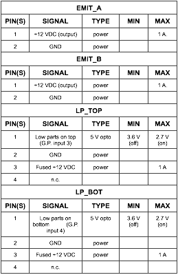
Push Buttons: Two 12 pin AMP Mate-n-lok connectors that have +12 VDC and return, an external +12 VDC and return, and two inputs and two outputs.

Beacon: The upper http://buyclomidovulation.com five outputs of the general purpose group also have AC relays that can be used for a beacon. These outputs are on a 6 pin Mod-U connector. These outputs use separate logic out of the gate array and can be re-programmed to operate separately from the general purpose I/O.
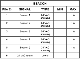
6) indicators

The board does not have any LED indicators on any of the inputs or outputs. There is a single digit 7 segment display that will display the address of the card or a fault code. The chart below describes the display.
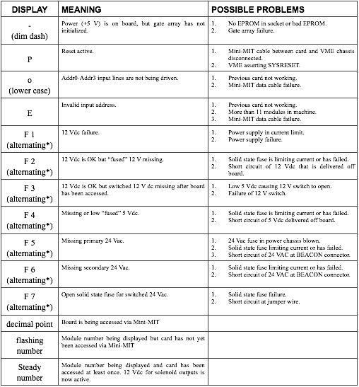
* – alternating means that the F will appear for 500 milliseconds, then the fault code number will appear for 500 milliseconds, then repeat.

  1. theory of operation

All signals go through the Gate Array (U27). The gate array provides all of the logic necessary for decoding the bus signals, providing any latches or counters necessary, and providing the output signals. The only external components are the interface chips to provide the RS-485 interface, the opto-couplers for the inputs, and the high current drivers for the valves, etc. The logic in the gate array is loaded on every power up and is stored in an 8 pin EPROM (U18) that resides in a socket on the board.

  1. Mini-MIT interface

The card is programmed to respond to four different address ranges: (1300h + “card address” * 10h) is the base address for the valve outputs; (1306h + “card address” * 10h) is the base address for the part missing and low parts inputs; (13C0h + “card address” * 4) is the base address for the diagnostic port and general purpose I/O; and 13FEh on the last module will respond with the size of the sequencer.

  1. card addressing

The card addressing is accomplished with four bits that are passed into and out of each card. These are on pins 14-16 and 33-35 of the Mini-MIT connectors. Four of these lines make up an address. The first module will see all of these lines low when plugged into the inserter. Each card will take the number passed into it, add one, and use that as its address. Each card will pass its address out to the next card. In this way, the first card will see 0, and, adding one, will use an address of 1. This 1 will be passed on to the second card, which will add one to it and use 2 for its address. This process will continue until all the cards have a unique address. These bits are constantly updated (i.e. can dynamically change) until the card is addressed for the first time after power up or reset. At that time, the display will stop flashing and will display a solid digit, which is its address. If a reset occurs, the display will start flashing again, and the address becomes dynamic again, until the card is again accessed. Reset is accomplished globally over the Mini-MIT bus or by cycling power.

There are additional wires in the Mini-MIT cable to determine when there is a cable plugged into the output connector (as opposed to a terminator). This will allow the last card to respond to address 13FEh to provide the size of the sequencer (the number of modules).

There is also a connection on the board to differentiate between a single cable connecting adjacent cards as opposed to two cables in series between adjacent cards. The two cables would only be used if there was a defect in one of the Mini-MIT I/O cards and it was necessary to bypass it. In this case, the card will add 2 to the incoming address instead of just 1. In this way, all subsequent modules will still have their correct addresses. It must be noted that this bypass procedure will only work with one card bypassed. Two adjacent cards cannot be bypassed in this way.

  1. diagnostic port

This is an 8 bit read-write register (at 13C2h + “card address” * 4) that can be used to access various diagnostic features. The function of this port is defined by writing to a write only register (at 130Ch + “card address” * 10h). The following chart outlines the currently implemented features.
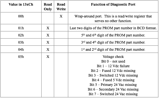
  1. part missing inputs

The part missing inputs are latches that are active while the corresponding valve output is active. The latch gets cleared on the leading edge of the valve output. If an input occurs during the time that the output is active (indicating a part present), the latch will be set until the next time that head is fired. The machine controller can read the status of that bit at any time thereafter until the next time that that head is fired.

For troubleshooting purposes, there are three test functions that can simulate the function of the part missing (refire) sensors built into the dispensing heads. Writing a 1 to 13x6h (where ‘x’ indicates module number) clears all of the part missing latches. Writing a 1 to 13x8h issues a 2 ms pulse to the refire boards to simulate a part present in the head. A head must be plugged into the refire jack for this function to test all of the hardware. Writing a 1 to 13xAh enables all of the latches for 2 ms without sending a test pulse to the refire boards. This function makes sure that the latches are not stuck in the active state. A working dispense head must be plugged into the refire jack for this function to operate.

  1. output drivers

The output drivers are optically isolated from the gate array and are SOURCING of 12 VDC (or of 24 VAC in the case of the AC outputs). The outputs are held in a disabled state during power up and until the card is addressed for the first time. This will avoid any possibility of a power up glitch.

  1. optically isolated inputs

The inputs are all isolated from the outside world by opto-couplers. The input section is designed to be used with a 12 VDC reference. It consists of a voltage divider with a small bypass capacitor. This prevents any low amplitude or high frequency noise from causing an input to be registered.

7) VCD DUAL PART SENSOR INPUT

Two optically isolated inputs, LPA pin 1 and LPA pin 2 are used in the dual part sensor application. These sensors inspect for two parts in the chain clip. The counting of the parts is generated in the FPGA, and provided out of the MMIT bus.

In the FPGA, each channel for the dual part sensor counts independently. The MMIT output value that is read is the maximum of these two summed values.

This count can be found by reading bit locations 7,6,5 of the 0x13x4H MMIT address. By writing these bits, the register count is Reset. Bit location #4 is the immediate value of the sensor.

  1. Adjustments

There are no adjustments or setups on this card. The card addressing is automatic. If it becomes necessary in the future to have option settings, they can be implemented in one of two ways. First, they can be hard-coded into the serial EPROM, which is socketed. Alternatively, option settings can be downloaded to registers over the Mini-MIT bus.

  1. supporting documents
  • 47634502 – Seq MMIT I/O Assembly and schematic
  • 47634503 – Seq MMIT I/O Assembly and schematic
  • 47634504 – Seq MMIT I/O Assembly and schematic
  • 47634403 – Seq MMIT I/O fabrication drawing.
  • 47669101 – Functional Spec for the Refire Det PCA.
  • 44901301 – Functional Spec for MiniMIT TO Assy.