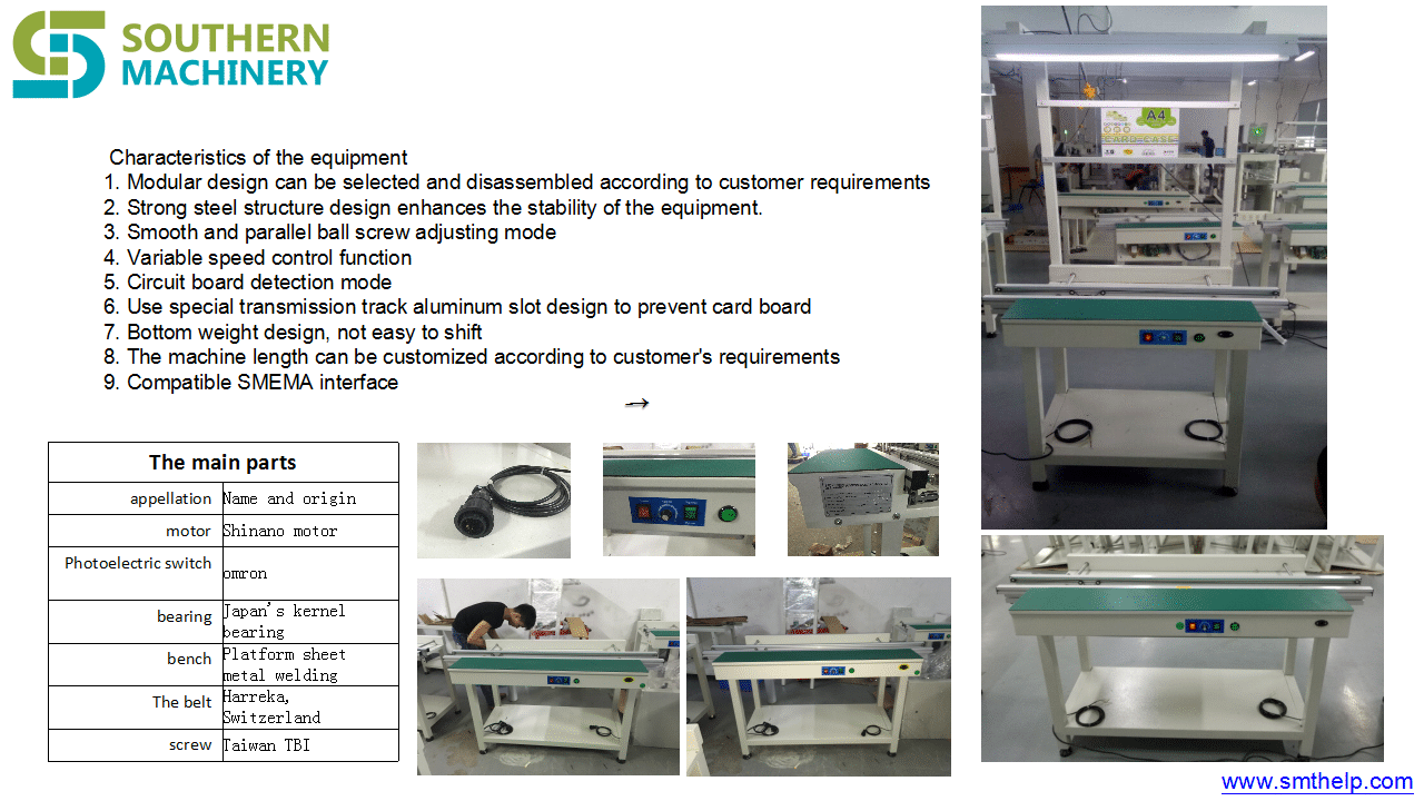
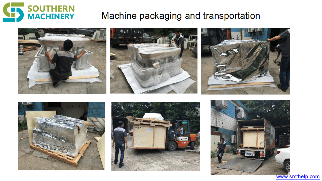
Automated optical inspection machine (AOI) is a new type of testing technology. It has
developed very rapidly in recent years. The structure of AOI consists of four parts: workbench, CCD camera system, electromechanical control and system software. When testing, firstly, the circuit board to be tested is placed on the workbench of the AOI machine, and the detection
procedure of the product to be detected is called out through positioning. The X/Y workbench
will send the circuit board under the lens according to the command of the setting program. With the help of the special light source, the lens will capture the image required by the AOI system and analyze it, then the processor will move the lens toward the lens. The next position is
collected for the next image and then analyzed, and the image is subjected to continuous
analysis and processing to obtain a higher detection speed. The process of AOI image
processing essentially digitizes the extracted image, and then compares it with the pre-stored “standard”. After analysis and judgment, it finds the defect to make a position prompt, and at the same time generates image text, and the operator further confirms or sends the repair station. Overhaul
Chip bonder counter can precisely count the SMD quantity, by adopting optical and electric sensor theory, using the corresponding relation between guide hole on the carrier and part, and by the special die and massive integrated circuit, chip bonder counter achieve zero error, and achieve convenient, quick counting, it is an effective auxiliary equipment for managing SMT material.
2、Product features
With full automatic way figure part quantity, it is convenient to count and delivery material. Easily operate it, original design defending strip dropping off decrease strip hurt to a smallest extent. It can count in forward direction or in backward direction, and it can be preset value, precisely figure out quantity with zero error. You also can install scanner gun and barcode printer, which is more convenient for managing operation..
3、product specification
Power: AC220V,50/60HZ,25W
Counter range: -99999–99999PCS
Profile size: L470W300H180mm
Weight: 10KG
4、Product Utility
Suit for SMD strip type of part
Strip wheel diameter: suit for any size
Strip pitch: 1,2,4,8,10,12,16,24,32,44,56mm ( Note: if pitch is smaller or wider, make it according to customer’s request)
Strip width: 4,6,8,12,16,24,32,44,56mm (Note: if width is smaller or wider, make it according to customer’s request)
5、Product Structure
this product have two types.
S-CC200 Standard chip bonder counter
2) S-CC202 inspecting missing type chip bonder counter
1、material reflector
2、Tray
3、Gear/motive pressing plate
4、monkey wrench
5、rocket head
6、free movable shoulder
7、location knob
8、display
9、key
10、power key
11、handle
12、glass fiber amplifier
13、glass fiber head to head emitter
二、Chip bonder counter attention
1,After unpacking, please count and make sure all accessories ready.
2,Before using chip bonder counter, please carefully read operating instructions and safe keeping.
3,Please check whether voltage specification conform to the electric supply.
4,Please check grounding properly, and guarantee safety of human body and part.
三、Chip bonder counter function key and operating instructions
1、Function key introduction
1)”PRINT”
Operation way: enter the key, you can print the counting part and quantity on the barcode by the barcode printer.
2)”SET”
Operation way: if the display shows 00000 in the left bottom, you can directly press the number key to input the counting part quantity; press the SET key one more time, the machine switches to manual mode, and the display shows ***** in the left bottom. Switch to manual mode or automatic mode using this key. (note: under automatic mode, you can preset a value before counting material, when machine turn to the presetting value, it will automatically stop, under manual mode, only if you press ” stop/zero clearing” key or it finishes all material, the machine will stop.)
3)”PITCH”
Operation way: after pressing this key, the pitch value in the display will flicker, then you can input the pitch value and press “ENTER” key, if no press after 5 second, automatically memorize, the machine will resume to standby status after one ticking sound.
4)”RIGHT” “FOREWARD/RIGHT”
Operation way: Pressing this key, start clockwise counting part, the numerical value is positive number, “BACKWARD/LEFT” on the contrary.
5) “STOP/ZERO CLEARING”
Operation way:
(1)Under counting or feeding back status, press this key, it will stop counting or feeding back.
(2)If under standby status, press this key over 2 second, the counting value will be cleared up.
(3)If under printing interface, press this key, return to main interface.
6)”SELECT”, this key is switching key for setting parameters in printing interface.
8)”Time/missing stop” key is switching key for motor rotating speed, press this key, LCD display will show motor speed will be switched among H(high speed), M(middle speed), L(low speed).
2、 Operation Flow
1)Connect the power cable to the master machine, and plug the AC220V power.
2)Turn on the POWER key on the panel of machine, at this time, LCD panel become light
3)Press PITCH key, set the pitch between counting parts, then Press “ENTER”, and put the part on the left tray.
4)Manually pull out the strip and put it between material guard plate and counting gear, make the first part and blank middle hole aligning the middle line of material guard plate.
5)Press “STOP/ZERO CLEARING” key for 2 seconds, make the value zero clearing. Note: when pulling the strip, counting gear will turn and count, pressing this key, make the value zero clearing.
6)Press “SET” key to switch to manual mode or automatic mode, when you select automatic mode, you should input a value which you are going to count, or the “FORWARD” motor won’t start.
7)Pull strip coiling to the blank tray (right tray) by your hand, press “FOREWARD/RIGHT” to begin counting.
8)When finishing preset value, motor stop. Impacted by the inertia theory, counting number may be more one or less one than the set number,
9)When finishing counting, press “BACKWARD/LEFT”, strip will coil back to the left tray, after finishing, rotation will stop.
2)Start bar code master machine power switch: power pilot light and ready pilot light are on, at moment, press FEED key of bar code master machine (automatic aligning key), make the paper automatically align. ( P.S: if power light is flickering, it denotes the machine is off line, please restart power or repress FEED key)
3、Print
Press “PRINT” key in the master interface, master interface will display printing interface, the first row in the interface show: company name (you can set it by yourself); the second row show: time, the last row show printing operation.
When entering printing interface, there is a flickering cursor in the third row, you can edit and modify the content in the cursor position.
In the printing interface, pressing LEFT/BACKWARD, you can make the cursor move left, pressing RIGHT/FOREWARD, you can make the cursor move right.
In the cursor position, you can directly input the number or letter, if you continually press any key among 0~9 key in a short time, you can switch between number and letter on the key. Among of them, pressing 1 key, you can switch to special symbol, Capital letter, small letter, and etc.
After editing each row, cursor will stay in the row you are editing, press “ENTER” key, it will display OK in the left of this row, which means the content is saved.
Note: Saving the content in the editing row, only when cursor is in this row, and then press ENTER, the content can be saved. For example, if you want to save the content in the first row and second row, when cursor is in the first row, you press ENTER key, at the moment, only the content in the first row is saved, the content in the second row can’t be saved.
In the printing interface, press SELECT key into printing parameter setting interface, XYWH: XXX XXX XXX XXX showed in this interface separately denote X axis, Y axis, width, height which you can set to the printed barcode paper.
Press STOP/ZERO CLEARING back to master interface
Press PRINT key one more time, you can print the content in the printing interface.
Tag: when scanner scans barcode, it will display in the printing interface, press PRINT key to print.
五、Easy trouble shoot
Failure
debug method
After turning on power, LCD no display, buzzer no sound
Please check if power cable drop off or fuse loosen
。After turning on power, LCD no display, buzzer sound
LCD display cable loosens or breakdown, please check or contact dealer to change.
LCD normally displays, but FOREWARD/BACKWARD can’t be started.
The counting quantity is more than or equal to the set value, or selecting automatic mode before counting but not set quantity, please refer to operating instructions.
2.Motor signal cable or power cable bad contact.
六、After-sale service a: (overall unit maintenance period for one year, master controller board maintenance period for three years, and tended for all life.) the following state happened is not in the free maintenance condition.
Machine is damaged under carried by your person by himself
In unstable voltage region, due to not using voltage stabilizer, cause component damaged.
Due to not using correct voltage, cause component damaged
Due to altering machine without the written approval of our company, cause the machine damaged..
Not selled by our company, but selled by dealer or other factory.
1. Obtain the proper shop packet and check order for build information. Pull all parts if any parts are missing, fill out a shortage sheet and give a copy to the appropriate material coordinator.
2. Pull the latest Electrical and Mechanical prints.
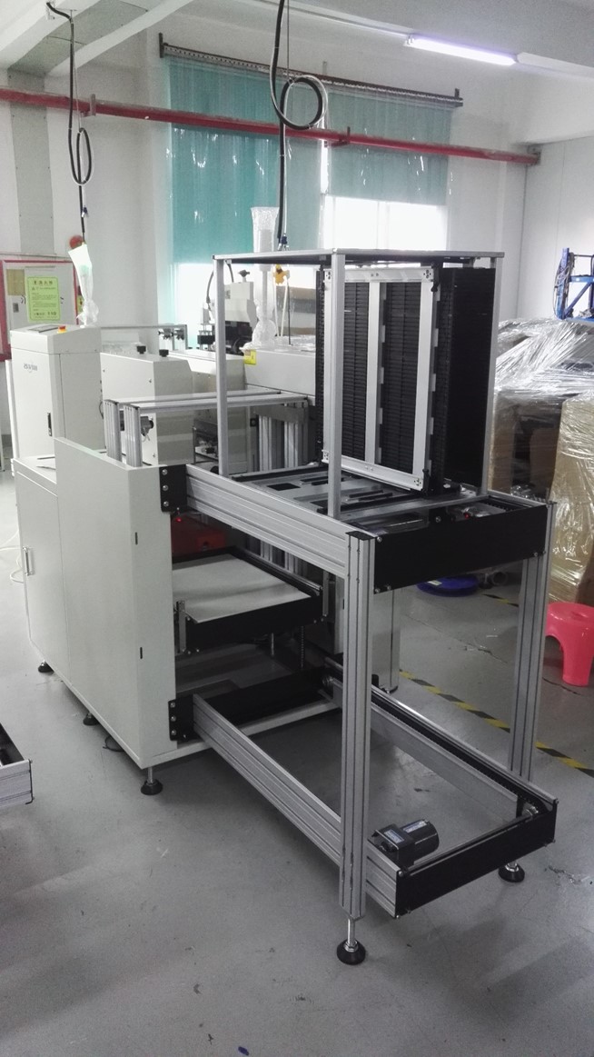
3. The following procedure is for a 29″ Destacker. Attach leg and control box to main beam. Leg should be flush to left side of main beam. Control box should be 3″ from right side of main beam. Attach width units to main beam, 4-3/8″ from either end square to main beam and Parallel to each other.
4. The following procedure is for the 44″ and 58″ Destackers Attach leg and control box to main beam. Leg 7-5/8″ from left end control box 7-5/8″ from right end. Attach width units to main beam 8.975″ from either end. Square to main beam and parallel to each other.
5. Attach rear rail to width supports parallel to main beam 3/8″ overhand from either end of main beam.
6. Level conveyor from side to side and front to back, off rear rail
7. Attach front rail to width supports. Match level to rear rail, especially front to back. Make parallel to rear rail. Make ends even with rear rail.
8. Install motors, pulleys, UHMW and belts on rails.
① PCB coordinate document template, it is the CSV file.
②Open control system main interface – > file – > new file – > import coordinate.
③ The CSV file, PCB general has Top layer and Bottom layer element coordinates, please confirm the current PCB is the top layer or the bottom layer, choose in the lower left corner coordinates. Then click the lower right corner → the import button.
Import the coordinate file function instructions:
Import the coordinate file function instructions
Option name
Operation
instructions
Coordinate
surface
Choose the Top layer and Bottom layer to import coordinate
components.
Flip coordinate
Select this option, will perform PCB flip horizontal coordinates
Flip Angle
Option
Allow Blank
When coordinate file have the margin, import coordinate indicates a blank space, must be made to modify the file and then import, avoid programming error.
Select this option, will ignore the coordinate file integrity, errors
may result in mounting components.
Grab the coordinate file by hand
Main interface in the upper right corner click open control system→Grab the coordinate To manually add the new coordinates
Manually add the new coordinates
① X Y positioning equipment function
X Y positioning equipment function
Option name
Operation
function
drop-down
options
Option
Choose the cursor, nozzle 1, nozzle 2 to grab positioning tool of the coordinate.
Open cursor
Close cursor
Back to Home
Execute
Machine return to original state
② Stepping set and X Y movement Function
Stepping set and X Y movement Function
Option name
Operation
Function
Stepping set
Option
Alternatively the step size of the X Y directions
X Y movement
Execute
Up and Down, Leaf and Right button could Operate X Y direction positioning, In operation, please don’t close to the machine tool
③ Manual input coordinate function
Manual input coordinate function
Option name
Operation
Function
Bit No.
Modify
General is number, To manager the PCB program more
clearly, fill the PCB current anchor element bit number.
Component Package
Fill the PCB current anchor element component package.
Note: After setting the above operation,, click “OK” to record coordinate current bit number. And then to do the next one. Directly to the center of the moving direction key to enter a number to setting, Click “OK” to finish record
coordinate current bit number.
Material Stack Configuration
Coil stock and tray stock
Coil stock: For the coil stock component putting.
tray stock: For the tray stock and tube IC component putting.
Material stack configuration function
Material stack configuration function
Material stack configuration function
Option name
Coil stock
tray stock
station number
According to the material stack number
Program Component
Click and choice of material stack put components corresponding
component model, choose components are not allowed to repeat
Material System
Click into the system of material select stack corresponding packaging material with
configuration
Component
Click into the system components and system interface to select material
Refers to the suction nozzle picking up speed, Normal: 20000pps.
The smaller data , the slower pick up speed
Pick up
Depth
Refers to the suction nozzle distance with the end face contact material stack material when pick up the component, Through the calibration can get picked up depth data, Special component separately select pickup
depth
Pick up
alone
To some special material stack, setting the speed the depth separately.
Multi-line batch modification Description
Multi-line batch modification Description
Description: Bit column number , hold down the left button to select a number of modifications can
make the following batch modify.
Option Name
Operation
Description
Center X
Modify
batch settings calibration center X coordinate of material stack
Center Y
batch settings calibration center Y coordinate of material stack
Broaching partial
X
batch settings Broaching partial X coordinate of material stack
Broaching partial
Y
batch settings Broaching partial Y coordinate of material stack
Pick up depth
batch settings pick up depth of material stack
Adapter nozzle
Option
batch settings adapter nozzle of material stack
Material stack debugging tools, data checking function description
Material stack debugging tools, data checking function description
Option Name
Operation
Description
Material stack test
Execute
Pick up test for calibration finished material station configuration
list
Save material
station to the file
Save the material station file for calibration finished material station configuration list, it could make it easy for the nest use.
Loading the material station
from the file
Can be loaded directly with the saved material station.
Check no material
Check the Program Component in the material station
configuration list for no material.
Check double
material
Check the Program Component in the material station
configuration list for double material.
Check nozzle
vacancy
Mounting Setting
Mount setting function and introduction
Programming parameters automatically get in after the second material Stack Configuration.
① Click the Align program into the coordinate system origin correction interface.
② Calibration Make sure whether the splint placed parallel to the PCB in place, subject to the plywood base point, and then calibrate.
③ Calibrating the far two point coordination ( reduce the error), Click OK after finished
calibrate.
Setting Mark point ( This setting must be completed – after operating alignment program origin )
Set Mark Point, choose a more independent square or circular Mark point as calibration points.( (Note: Mark point usage; in the fourth programming due to the PCB board or puzzle on the origin lead to error, click Mark point to automatic correct board )
Calibration ( This setting must be completed – after operating alignment program origin )
Calibration is used to correct a separate placement coordinate with the actual Mark-point calibration.
Other Setting
① Reset the default placement coordination, mounting XY coordinate reply for source file coordination.
② Check invalid pick up material station, check whether the configuration is complete.
Puzzle calibration Make sure whether the splint placed parallel to the PCB in place, subject to the plywood base point, and then calibrate.
① Manual correction: Click the PCB list of coordinates to enter the calibration correction, respectively coordinate 2 far point calibration.( reduce the error), If there is the puzzle PCB, then do the first PCB, and send and so no. The same way to calibrate.
② Mark point automatic correction: one-time auto-complete according to automatic Mark point on board.
Program Runs
Program option function 5.1.1 Function
Option Name
Operation
Description
Base plate Depth
Calibration
Nozzle and plywood PCB contact distance, setting through the
calibration.
Optimization Option
Option
Dual stepper reel, can improve the placement rate.
The default double election: if canceled a nozzle will not be placement relative programming can not be involved in SMT production process, two nozzles are canceled, the program
can not be generated.
Run the patch
Function
Option Name
Operation
Description
Test mounting
Option
Select the test mounting, roll feed zone does not feed tray,
please do not put components, SMT will simulate patch
Selected, SMT work when other material stack error will end the current SMT all the work, and stop running
Speed Stalls
Set
The smaller stalls, The slower SMT run speed
Starting line number
It may be the current line number bit number for starting SMT
placement
Back Home
Execute
Back to initial state.
Start
Start SMT run
Pause / Resume
When SMT work, click this button, it could pause, and click
again, it could resume to work.
End
End the current work.
5.3 Mount coordination Preview
Function: You can preview the imported PCB plots, red for the selected package components , it can zoom right to select the bit number to view the preview package management.
High mixed, high value, low volume business expertise service.
Flexible operation, fast response and total satisfaction.
Good after-sales and extra value creation services including logistics support, valet procurement, supplier audit service and in factory office offering.
The following procedures explain how to properly clean and test an ESD surface.
Clean an ESD Surface
Do not use abrasive or highly alkaline cleaners on polycarbonate. Never scrape polycarbonate with squeegees, razor blades, or other sharp instruments. Benzene, gasoline, acetone, or carbon tetra chloride should never be used on polycarbonate. Do not clean polycarbonate in the hot sun or at elevated temperatures.
Using a sponge or soft cloth, wash the ESD-protected surface with either a mild detergent or Windex product and lukewarm water.
After washing, rinse with water and dry thoroughly with a chamois or moist cellulose sponge to prevent water spots.
To protect the ESD surface after rinsing and drying, recommends applying Kleenmaster Brillianize®. This application helps to maintain the static dissipative coating and reduce the accumulation of dust.
Test Static Dissipative Covers
Periodically and after maintenance, check the machine covers to determine if the dissipative qualities of the cover have changed. The following procedure ensures that static dissipative covers are in fact dissipative.
Tooling
Surface resistance meter (such as 3M 701 Surface Resistance meter and probe).
Comments
The surface resistance should be less than 109 ohms in all areas. If the cover package is no longer dissipative, contact you Universal Instruments Corporation sales representative.
Procedure
Clean the static dissipative covers using the Clean ESD Surface procedure to ensure the accuracy of the test.
Using the surface resistance meter, follow the instructions provided by the manufacturer to measure the surface resistance of both the inside and outside of the covers. Measure the resistance at all four corners and at several areas in the middle of the cover. This test checks the integrity of the ESD coating.
Connect the ground path resistance probe to the meter and chassis ground.
The path to the ground should not be higher than the surface resistance. If it is, clean the frame connections, repair loose or corroded fasteners and ground straps, and check tracks for dirt and/or corrosion.
4. Measure the ground path from the covers to the chassis ground. Take this measurement from both surfaces and all four corners of each cover.





















 Programming parameters automatically get in after the second material Stack Configuration.

 calibrate.


 Function: You can preview the imported PCB plots, red for the selected