
Ergonomics Design Checklist for Electronic Manufacturing PCBA

Preface:

The goal of any ergonomics process is to eliminate or prevent exposure to the root causes of injury; Force, Frequency, and Posture. These risk factors act alone and in combination to slowly deteriorate the soft tissues of the body, potentially leading to a permanent disability (work-related musculoskeletal disorder) over time.

The most effective means by which to control these risk factors is through the implementation of thoughtful engineering practices. In other words, designing all new operations, and/or modifying existing operations to fit the human body.

The checklists below specify important criteria to be taken into account when evaluating the ergonomic acceptability of existing workstations, optimizing the design of new assembly lines or work cells, and/or purchasing tooling and equipment from external vendors.

The 8 checklists, each focused on a unique and specific set of criteria, are as follows:

  • Standing Workstation – Design Criteria
  • Seated Workstation – Design Criteria
  • Work Reach Envelope – Design Criteria
  • Visual Work Envelope – Design Criteria
  • Work Chair – Design Criteria
  • Tooling – Design Criteria
  • Work Area Clearances – Design Criteria
  • Access Port Clearances – Design Criteria

The criteria outlined in each checklist are based on anthropometric studies of healthy working-age adults and are intended to ensure that the majority (90%) of the working population can complete their job duties in neutral body postures; extremely tall or extremely short individuals may require special accommodation.

It is also important to note that the guidelines are generic in nature and in some instances, must be adapted to a specific or unique work environment.

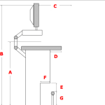
The following table outlines design criteria for workstations in which the operator is standing:
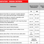
Figure 1: Standing Workstation
The following table outlines design criteria for workstations in which the operator is sitting:
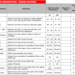
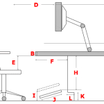
Figure 2: Seated Workstation
The following table outlines appropriate horizontal reach distances according to type/frequency of work being performed:
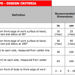
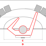
Figure 3: Work Reach Envelope

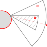
The following table outlines the optimal visual angles for minimizing non-neutral head/neck postures:
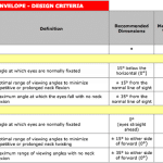
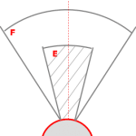
Figure 4: Visual Work Angles

The following table outlines appropriate design criteria for a work chair:
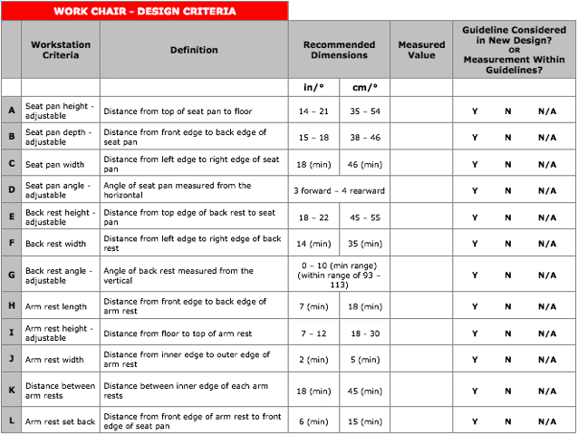
Additional Criteria:

  • Ensure seat pan has a waterfall-shaped front edge to minimize compression forces to the underside of the thighs – the radius of the front edge curve should be no less than 4 cm (1.5″) and no greater than 12 cm (5″)
  • Cushioning materials within the seat pan and back rest should be expanded flexible urethane foam of either flat slab, sculpted slab, or moulded construction
  • Chair should be equipped with a 5-caster base to minimize tipping
  • Controls should be operable form the usual seated working posture, have markings visible from a seated position, not require undue force exertion for activation, not require special tools for adjustment, and designed to prevent unintentional actuation
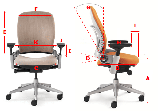

Figure 5: Work Chair
The following table outlines appropriate design criteria for industrial hand tools:
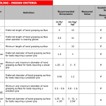
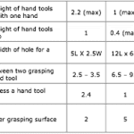
Additional Criteria:

  • Air exhaust should be directed toward the front of the tool rather than toward the operator’s hand/wrist
  • Any tools surfaces that generate heat or cold and are in contact with the hands should be insulated
  • Strip triggers are preferred over single finger triggers to provide operators with more options and encourage multi-finger activation
  • If possible, thumb triggers should not be used because the thumb is primarily used as a grip stabilizer. Using the thumb to trigger a tool reduces the stability of the tool
  • Tools used to cut or exert large forces should be designed with stops or guards to prevent slippage of the hand
  • Tool trigger activation forces should not exceed 2.4 lbf. or 10 N
  • Tools weighing in excess of recommended guidelines should be suspended from a counterbalanced arm or tool balancer, particularly for overhead work
  • Operators should be provided with anti-vibration gloves when using tools that vibrate
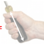
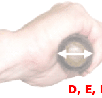
Figure 6: Tooling – Handle Length and Diameter
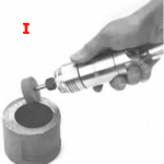
Figure 7: Tooling – Weight
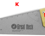
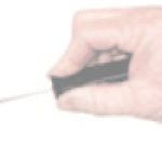
Figure 8: Tooling – Cutouts and Grip Spans
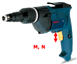
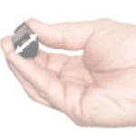
Figure 9: Tooling – Triggers
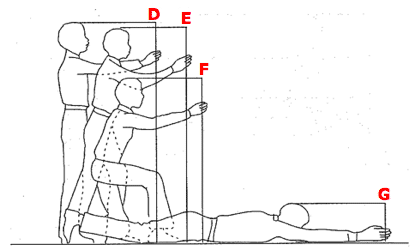
The following table outlines appropriate design criteria for work area clearances, critical for machine maintainability:
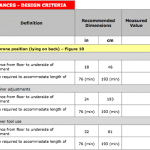
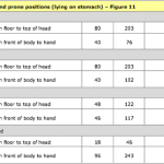
Figure 10: Work Area Clearances in Prone Position – Lying on Back

Figure 11: Work Area Clearances in Prone Position – Lying on Stomach
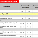
The following table outlines appropriate design criteria for access port clearances, critical for machine maintainability:
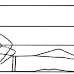
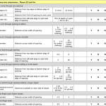
Figure 12: Full Body Access Port Clearances
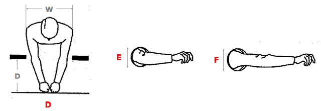
Figure 13: Arm Clearances
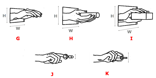
Figure 14: Hand Clearances
Auto Insertion Machine – Insert Errors troubleshooting for Electronic Manufacturing PCBA

TroubleshootingTable-InsertErrors

The following table lists possible error scenarios for insert errors.

Troubleshooting Table – Insert Errors
Indicated Trouble Probable Ca use Corrective Action
1 Component leads do not enterprinted circuit board. Prin ted circuit board dril led incorrectly. Replace out of tolerance printed circuit boards.
Printed circuit board not properly located. Correct board location problem.
Pattern program coordinates are incorrect. Enter correct coordinates.
Machinezerosetup out of tolerance (X, Y,

head, or clinch axes).

Refer to maintenance manual and set each

axis to specification.

Incorrect offset values. Enter correct offset values.
BEC setup out of to lerance. Referto maintenance section and set up

BEC.

Worn tooling. Replace worn tooling.
Bent or out of spec input. Correct badinput. Refer to Component Transfer Errors table.
VCD Only:
Centering mechanism out of adjustment.
Refer to maintenance section and adjust centering mechanism.
VCD and Radial Only:
Incorrect component loaded in dispensing head.
Load dispensing head with correct component.
Radial Only:

Poor transfer of component from

component transfer assembly to head.

Set up component transfer assembly per maintenance manual.
Radial Only:

Incorrect dispensing head alignment/setup.

Set up andalign dispensing head per maintenance manual.
Radial Only:

Insert headjaws sluggish orout of

alignment.

Perform preventive maintenance, set up, and aligninsert head jaws per

maintenance manual.

Radial Only:

Defective carrier clip spring or clamp.

Repair or replace as necessary.
Radial Only:
Insertion tooling clamp worn or spring fatigued.
Repair or replace as necessary.
2 VCD and Jumper Wire Only:

Machine does not detect insert

errors.

Continuity error fai lure. Referto theClinchAssembly tableinthis document.
3 Machine reports insert errors when inserts are good. Clinch malfu nctio n. Refer toClinch Assembly tab le.
Continuity circuit problem. Debug continuity circuit.
Clinch setup inco rrect/clinch is di rty. Perform clinch preventive maintenance per

maintenance manual.

4 Component not centered. Centering mechanism out. Refer to maintenance section and adjust

centering mechanism or replace centering inserts.

5 Machine fails to report insert errors Sho rted or ja mmed clinch. Perform clinch preventive maintenance per maintenance manual.
Switches not set correctly or/failed Multi Input I/O card. Set switches per PC Jumper Config/Replace Multi Input I/O card.
6 One Component lead does not enter printed circuit board Printed circuit board is not drilled correctly. Replace out of tolerance printed circuit boards.
Printed circuit board is not properly located. Correct board location problem.
Defective carrier clip spring or clamp. Repair or replace as necessary.
Pattern program coordinates are incorrect. Enter correct coordinates.
Radial Only:
Incorrect component loaded in dispensing head.
Load dispensing head with correct component.
Radial Only:

Poor transfer of component from

component transfer assembly to head.

Set up component transfer assembly per maintenance manual.
Radial Only:

Incorrect dispensing head alignment/setup.

Set up and align dispensing head per maintenance manual.
Radial Only:

Insert head out of alignment.

Set up and align insert head jaws per

maintenance manual.

Radial Only:

Insertion tooling clamp worn or spring

fatigued.

Repair or replace as necessary.
7 Component leads are not cut and clinched Clinch is jammed . Clear clinch jam.
Clinchheight is set toolow. Adjust clinch height per maintenance

manual.

Head to clinch alignment is not correct. Adjust alignment per maintenance manual.
8 Component leads are too long after cut and clinch Clinchheight is set toolow. Adjust clinch height per maintenance manual.
Head to clinch alignment is not correct. Adjust alignment per maintenance manual.
Head to circuit board clearance is not set prop erly. Adjust head height per maintenance manual.
Radial Only:

Pusher tip height is incorrect.

Ensure pusher tip is installed properly.

Auto Insertion machine – Clinching problem Troubleshooting guide for Electronic manufacturing PCBA

Troubleshooting Clinch Problems

The following paragraphs will detail various clinch problems and the procedures required to resolve these problems. The types of problems presented include clinch form problems and clinch functional problems.

ClinchFormProblems

The following presents various form problems that may be encountered, the general cause of the problem and the resolution of the problem.

Problem:LeadLengthsNotEqual(VCDandJumperWire)

(VCDpictured.)

Cause

Clinch to Head X direction misalignment.

PossibleResolution

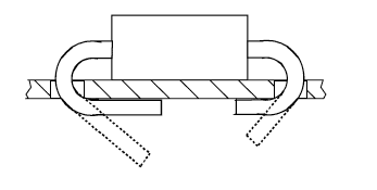
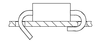
Realign Clinch to Head. Refer to Clinch to Head Alignment Procedure. Cutter Set Up (clinch angle) might need to be readjusted.

Problem: Unequal Lead Angle (VCD Only)

(VCDpictured.)

Cause

Cutter linkage not adjusted properly.

PossibleResolution

Adjust leads to desired angles. Refer to Cutter Set Up procedure.

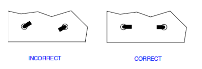
Problem: Clinch Leads Toed – Same Direction (VCD and Jumper
Wire)

INCORRECT CORRECT
(VCD pictured.)
Cause
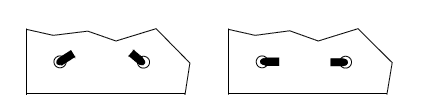
Clinch to head Y direction misalignment.
Possible Resolution
Realign Clinch to Head. Refer to Clinch to Head Alignment procedure.
Problem: Clinch Leads Toed – Opposite Directions (VCD and
Jumper Wire)

(VCD pictured.)
Cause
Clinch not aligned to head.
Possible Resolution
Realign Clinch to Head. Refer to Clinch to Head Alignment Procedure.

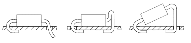
Problem:MisformedLead(s)withPossibleBurr(VCDOnly)

(VCDpictured.)

Cause

Worn cutter or cutter bushing.

PossibleResolution

Inspect and replace cutter and cutter bushing.

Problem:MisformedLead–Various(VCDOnly)

(VCDpictured.)

Cause

Lead hitting anvil/bushing.

PossibleResolution

Realign Clinch to Head. Refer to Clinch to Head Alignment Procedure.

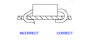
Problem: Clinch Not Tight to Board (VCD and Jumper Wire)


(VCD pictured.)
Cause
Anvil height too low.
Possible Resolution
Readjust anvil height. Refer to Anvil Height Adjustment procedure.
Cause
Improper dimensions for the component in the Component Database.
Possible Resolution
Measure the component, and fix the component definition

ClinchFunctionalProblems

The following presents various functional problems that may be encountered, the general cause of the problem and the resolution of the problem.

Clinch Functional Problems
Problem Cause Possible Resolution
1 Motion fault on insertion head. Anvil setting too high. Reset anvilheight. Refer toAnvil Height

Adjustmentprocedure.

2 Motion fault onanvil up. Cutter backstroke too large. Reset cutter backstroke. Refer to Cutter

procedure.

Servo Amplifier problems. Refer to Servo Chassis Assembly documentation Status Code
troubleshooting charts.
Wiring problems. Repair or replacefaulty wiring.
3 Machine status “Waiting for Cutter In” Cutter cylinder binding. Worn O-rings, lubrication. Repair, replace and lubricate O-rings.
Pneumatic valve/solenoid failure. Repair or replace valve/solenoid.
Failed/pinched pneumatic lines. Repair or replacefaulty pneumatic lines.
Wiring problems. Repair or replacefaulty wiring.
Cutter timing stroke greater than 45 msecs. Check IM Diagnostics Rapid Motion Timing

and adjust to 35-45 msecs.

REDUCE PCBA COST BY USING SOUTHERN MACHINERY MACHINES

REDUCE PCB ASSEMBLY COST BY USING SOUTHERN MACHINERY MACHINES

Choosing which surface mount technology machine or auto insertion machine is best fitted to your pcba design plays a big role in your production. In order to make this easier for you we’re introducing our SMT/THT Machines.With Southern Machineries – Chine we aim to reduce your cost and increase your production ( Our products). While you are reconciling your BOM / Order keep a lookout for the “Southern Machinery” sign. We recommend that you use these machines since we likely already have them in stock.

We have put together a nice products with complete descriptions about Peripheral Equipment. Also check out our shop page and do online shop from our website for your machines and spare parts.

WE FACILITATE YOU AND WISH TO INCREASE YOUR PRODUCTION THROUGH OUR NEW TECHNOLOGY

· SMT/THT MACHINES PRODUCTION & SPARE PARTS
· TIME CRITICAL PRODUCTION
· COMMITMENT TO CUSTOMER SERVICE
· BEST QUALITY AND DELIVERY PERFORMANCE
· FAIR AND COMPETITIVE PRICING/COST
· RAPID RESPONSE TO QUOTE REQUEST
· ONLINE SUPPORT PROGRAM
· TRAINING PROGRAMS
· FLEXIBILITY
SCHEDULING
· STOCK/ INVENTORY PROGRAM

IF you ever have any question, please feel free to reach out to us. We’d love to hear from you. My email is info@smthelp.net and our phone number is 0755-83203237

SOUTHERN MACHINERY – BOARD HANDLING SYSTEM

BOARD HANDLING SYSTEM

I’d like to announce that we’ve added a new section to our website called " Board Handling System " in product category.
Over the years, customers have asked us how they can know specifically about Board Handling System Machines so that they’re as simple for Southern Machinery to provide them specific machines as possible according to the clients requirement and specifications. A lot of questions revolve around how these machines are operated, what are the specifications, what machine can be best fitted for their companies etc. So the very first and few products we put together is called "Board Handling System “which can be found here.
We’ll try to update this page whenever we find customers asking us such questions regularly. If you have a question about what specific machines are your requirements, how to get maximum ROI, how to handle and fix your problems of your smt/tht machines etc. please get in touch. We’re happy to help.

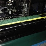
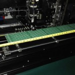
Are you looking for big PCB board (length 1000mm) auto insertion solution for electronic manufacturing

STRIVING FOR EXCELLENCE AND EVERYTHING WE SAY AND DO

Southern Machinery is affianced in supplying a wide range of PCB Assembly Equipments/Conveyors that is fabricated using high grade material, procured from quality conscious vendors. We are continually reinvests in the very latest technology and equipment based on customer demands and industry trends. Our Machines are widely acclaimed for easy adjustment, Low maintenance and high operational efficiency.

SOUTHERN MACHINEY SALES AND SERVICES COMPANY :

· SMT/THT MACHINES PRODUCTION & SPARE PARTS
· TIME CRITICAL PRODUCTION
· COMMITMENT TO CUSTOMER SERVICE
· BEST QUALITY AND DELIVERY PERFORMANCE
· FAIR AND COMPETITIVE PRICING/COST
· RAPID RESPONSE TO QUOTE REQUEST
· ONLINE SUPPORT PROGRAM
· TRAINING PROGRAMS
· FLEXIBILITY
SCHEDULING
· STOCK/ INVENTORY PROGRAM

TO INQUIRY ABOUT SMT / THT / AUTOMATIC LEAD PICK AND PLACE / INSERTION MACHINES AND UIC,TDK, PANASONIC, SCIENCGO SPARE PARTS, REMEMBER SHENZHEN SOUTHERN MACHINERY SALES AND SERVICES COMPANY – A LEADING NAME IN SMT/THT MACHINES PROVIDER WORLDWIDE.

Are you looking for 10 mm lead span Radial component auto insertion machine

Southern Machinery Sales and Services Company provide and support a large number of SMT /THT & Auto Insertion Machines models. Since with the day to day development of technology and with the passage of time new machines are coming to market that will need to be supported in the future.

I would like to ask for your input on new machines or technologies that you are considering or have already committed to in your facilities.

Are you looking for higher feeder capacity machines to reduce the changeover time from product to product or group to group? Are you looking for a surface mount technology one stop solution line which provides you $50k per month and mix production on monthly basis? Are you still using old technological Surface mount Technology machines?

Southern Machinery provides many different types of products, especially across different types of machines, then please let me know also as we have solutions for these challenges too. To know more please click.

http://www.smthelp.net/advanced-pcb-assembly-machines-and-spare-parts/

http://www.smthelp.net/smt-high-quality-automatic-dip-soldering-machine/

http://www.smthelp.net/benefits-of-smt-tht-pcba-manual-to-auto-insertion/

AN OVERVIEW OF THE PCBA PRACTICE INVOLVED IN SMT BOARD, USING PICK AND PLACE TECHNIQUES

AN OVERVIEW OF THE PCBA PRACTICE INVOLVED IN SMT BOARD,
USING PICK AND PLACE TECHNIQUES

Within a printed circuit board electronics assembly / production or manufacturing process, there are a number of individual stages. However it is necessary for them all to work together to form an integrated overall process. Each stage of assembly and production must be compatible with the next, and there must be feedback from the output to the input to ensure that the highest quality is maintained. In this way any problems are detected quickly and the process can be adjusted accordingly.

PCBA PRACTICE OVERVIEW

The various stages in the PCB assembly process including adding solder paste to the board, pick and place of the components, soldering, inspection and test. All these processes are required, and need to be monitored to ensure that product of the highest quality is produced. The PCB assembly process described below assumes that surface mount components are being used as virtually all PCB assembly these days uses surface mount technology.

Solder paste: Prior to the addition of the components to a board, solder paste needs to be added to those areas of the board where solder is required. Typically these are as are the component pads. This is achieved using a solder screen.

The solder paste is a paste of small grains of solder mixed with flux. This can be deposited into place in a process that is very similar to some printing processes.

Using the solder screen, placed directly onto the board and registered in the correct position , a runner is moved across the screen squeezing a small mount of solder paste through the holes in the screen and onto the board. As the solder screen has been generated from the printed circuit board files, it has holes on the positions of the solder pads, and in this way solder is deposited only on the solder pads.

The amount of solder that is deposited must be controlled to ensure the resulting joints have the right amount of solder.

Pick and place: During this part of the assembly process, the board with the added solder paste is then passed into the pick and place process. Here a machine loaded with reels of components picks the components from the reels or other dispensers and places them onto the correct position on the board.

The components placed onto the board are held in place by the tension of the solder paste. This is sufficient to keep them in place provided that the board is not jolted.

In some assembly processes, the pick and place machines add small dots of glue to secure the components to the board. However this is normally done only if the board is to be wave soldered. The disadvantage of the process is that any repair is made far more difficult by the presence of the glue, although some glues are designed to degrade during the soldering process.

The position and component information required to programme the pick and place machine is derived from the printed circuit board design information. This enables the pick and place programming to be considerably simplified.

Soldering: Once the components have been added to the board, the next stage of the assembly, production process is to pass it through the soldering machine. Although some boards may be passed through a wave soldering machine, this process is not widely used for surface mount components these days. If wave soldering is used, then solder paste is not added to the board as the solder is provided by the wave soldering machine. Rather than using wave soldering, reflow soldering techniques are used more widely.

Inspection: When the boards have been passed through the soldering process they are often inspected. Manual inspection is not an option for surface mount boards employing a hundred or more components. Instead automatic optical inspection is a far more viable solution. Machines are available that are able to inspect boards and detect poor joints, misplaced components, and under some instances the wrong component.
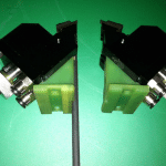
Test: It is necessary to test electronic products before they leave the factory. There are several ways in which they may be tested. To know others methods , consult to our Engineering department.

Feedback: To ensure that the manufacturing process is running satisfactorily, it is necessary to monitor the outputs. This is achieved by investigating any failures that are detected. The ideal place is at the optical inspection stage as this generally occurs immediately after the soldering stage. This means that process defects can be detected quickly and rectified before too many boards are built with the same problem.

As a final point

The PCB assembly process for the manufacture of loaded printed circuit boards has been considerably simplified in this overview. The PCB assembly and production processes are generally optimized to ensure very low levels of defects and in this way produce the highest quality product. In view of the number of components and solder joints in today’s products, and the very high demands placed on quality, the operation of this process is critical to the success of the products that are manufactured.

TO INQUIRY ABOUT SMT / THT / AUTOMATIC LEAD PICK AND PLACE / INSERTION MACHINES AND UIC,TDK, PANASONIC, SCIENCGO SPARE PARTS, REMEMBER SHENZHEN SOUTHERN MACHINERY SALES AND SERVICES COMPANY – A LEADING NAME IN SMT/THT MACHINES IN WORLDWIDE.

MECHANICAL DESIGN AND FABRICATION OF SMT AUTOMATIC PICK AND PLACE MACHINE

MECHANICAL DESIGN OF THREE AXIS MOTION (SMT PICK AND PLACE ASSEMBLY)

· SCARA ROBOTIC ARM.

In SCARA robotic arm the robotic arm is used for the placements of the SMT components. Picture shows a robotic arm pick and place machine.

· 3-Axis movement machine.

In 3-axis machine a nozzle is attached to a plotter-like device to allow the nozzle head to be accurately manipulated in three dimensions. Additionally, nozzle can
be rotated independently. Figure 2.3 shown a belt driven 3-Axis pick and place machine. In some machines lead screws are also used instead of belts.

Limitations

The length and breadth of the machine is limited due to the bending of the rail rods. The rods get deflected due to the weight of head (pick and place nozzle assembly). When the length and breadth of the machine is increased the deflection of the structure in downward direction also increases. Therefore they are not increased beyond a certain limit. For the same reason, the diameter of the rail rods is also kept at a certain value and is not decreased as for larger diameter of the rods weight also increases.

We choose belt driven mechanism to drive movement of assembly. Belt greatly increases the speed of the machine but it decreases its precision. Increasing the diameter of the pulleys do increases the speed of the machine but it decreases its precision. Due to this reason, the diameter of the driving pulleys is also kept small.

Head (Pick and Place Assembly)
It is most vital part of Pick and Place machine from speed and accuracy prospect. Speed of machine is in direct relation with the speed of head. It is actually speed with which machine can pick and place components and it is usually measured in parts per hours (PPH).

1. Types

Pick and Place heads can be classified on the basis of following factor,

1. Number of nozzles on head

Most industrial machine has several nozzles on head. They pick up several components during pick up run and place these components during place run. In some kinds of machines components are feed into multiple heads (like bullets in a chamber), these components are then fired one by one on PCB. Picture below shows commercial multiple nozzle head.

2. Speed

Speed can be increased by multiple factor by using multiple heads on a single machine or multiple nozzles on single head. Small projects or research based Pick and Place machines usually have single head with single nozzle. These machines have speed around 1000pph to 4000pph.

Drive mechanism(motor driven or pneumatic driven)

Most common mechanism for driving head up and down is motor driven. Motor can be connected to lead screw system to drive nozzle up and down. In order to attain high speed belt driven system is used. picture shows a pneumatic driven head.

Many industrial Pick and Place machines use pneumatic drives to move nozzles up and down. Selection of drive mechanism depends on availability and price of component. In our machine we will be using motion based on belt driven mechanism due to the low price of DC servo motor and ease of control.

Features

Common features that typical Pick and Place head have are:
· Shock absorption
· 180 degree component rotation angle Controlled suction
· Small pick place transient overshoots

1. Limitations

Most prominent limitations on Pick and Place head design are:

Maximum size of head

Increasing the size of head decreases the work area for Pick and Place machine. Small head causes the designer to compromise on many quality factors. Designers are carved to use small low torque motors, small diameter guiding rods and small number of linear bearings.

Maximum speed of head

Increasing the speed to pick and place components cause the danger of dropping the component from vacuum nozzle. Head need a minimum amount of time for settling before pulling up and putting down component. Also heads speed is limited by control speed of vacuum pump and time delay of image processing processor

1. Important Considerations

Shock Absorbing

There is always risk of slight shock to the nozzle while picking or placing components on PCB. These shocks if not avoided can cause nozzle to bent from top causing uneven suction distribution over component surface. This uneven distribution of suction will cause frequent dropping of SMT components.

b. Nozzle Changer

SMT components are available in different sizes. Same nozzle cannot be used to pick and place SMT components of different sizes. Nozzles of specific gauge are used to pick place components of different sizes. In order to cope with this limitation head needs to be designed such that nozzles can be changed either manually or automatically

c. Availability of Nozzles

There is a large industry dealing with manufacturing nozzles for Pick and Place machines. These companies make nozzles for almost every type of component. But because of non-availability of nozzles in our region, nozzles are needed to be fabricated.

Feeders

As SMDs are itself special components because of their size and packing. So getting these component ready to be picked needs special devices called as feeders. Feeders are specially designed to feed the components to the machine.

Tape Feeders

These are specially designed feeders for the components packed in the form of long tapes. Following online links were examined:
Tapes are such that they have holes on their side. These holes are of standard size and are distant equally. As the figure 2.6 below shows the driving gear for the tape for its motion on the feeder as the gear moves it pulls the tape with its teeth.

Consulting patent[6] of different feeders we see they are mostly belt driven with driving element i.e. motor on side and driver on the other end. Figure 2.7 shows the gear for reel movement at 55 and being driven by 57 at the other end which can be driven by a motor.

From the complexity of feeders coping with tapes inside them was bit difficult to design so the having the tape completely isolated from the inside of feeder was considered most practical design.
As components are covered with protective tape on the top so this tape should be removed before component could be accessed. For this following simple design figure 2.8 below was considered. It is a commercial feeder by PCB unlimited for SMT components. It shows the tape removing pulley at the top and main components being moved forward.
For the position of each feeder on the machine we considered a product by LPKF called proto place. It is a semi-automatic machine for SMT components pick and place as shown in picture.

Proposed Specs of Machine

For any type of SMT/THT specification of Machine according to your requirements and Company setup, Please consult to our Engineering department at Shenzhen Southern machinery Sales and Services Co; Ltd.

ARE YOU LOOKING FOR AUTO COMPONENTS INSERTION / PLACEMENT SYSTEM for electronic manufacturing

AUTO COMPONENTS INSERTION / PLACEMENT SYSTEM

Efforts to automate PCB assembly (stuffing) have progressed from hand-formed components leads and manual insertion guided by blueprint. On up to fully automatic component insertion machines. The present state of the art involves either islands of automation (group of machines) bridged by sophisticated material handling. Or an array of machine setup for continuous in line assembly. All types of components are now being sequentially inserted, including axial, radial, DIP, surface –Mount (lead-less) and odd shaped components, the latter via special robotics.

Benefits of Automation

Full automation of the component insertion/ placement operation provides the user with benefits such as :

· Consistency of products quality and quantity
· Automatic inventory tracking

Additional benefits grained from these factors include reduced labor cost , Reduced reworks and an improvement in production process.
Automatic component insertion system offer a consistent production volume, and by using on-line test and verification system, allow the user to control the quality of output “Automated system are usually justified on this basis”
Speed and quality are therefore considered the most important benefits offered by both automatic insertion of leaded components are surface- mount placement system.

Recent Improvements

Automated board handing a wider range of insert able components and the increased availability of surface –mount pick-and-place system represent the most significant recent advances in PCB assembly technology. Surface mount system are now offered over a broad price range and performance capability, from the large, high volume systems costing from $ 400,000 to $850,000 depending upon options, to medium- volume systems, and on down to lower- volume units. Some of the larger surface – mount systems have been imported to provide a recycling features whereby boards with missing chips are automatically returned to the pick and place station. Most system have also been expanded to accommodate a wider range of components and some now incorporate an optical system to automatically correct for board misregistration.
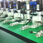
Leaded systems

Leaded automatic component insertion system such as axial, radial and DIP , represent a more mature technology. Axial lead insertion is really comprised of a family of machines, such as reel packaging systems, sequencing system (where applicable), component verifies and the component insertion machine
Automatic insertion of radial leaded components is complicated by varied body sizes and lead diameters. These problems were overcome by handling all radial lead components by the leads rather than the body, and by reel taping the leads at standardized spacing. Some components have been difficult to handle. For example, the TO-92 transistor with its three leads and 0.014in. lead diameter was not capable of being automatically inserted until a few years ago. Automatic DIP insert er are designed to DIP lead row spacing of 0.300in., 0.400in and 0.600in. The newer systems can also insert DIP sockets, DIPs into sockets and mount decoupling capacitors.

Odd – Shapped Components

Accurate component placement is a basic requirement for any picks and place machine. The first step towards accurate placement is accurate centering, or measurement of the component’sposition on the placement head. One of the most widely used centering methods for ICs, connectors, and oddshaped components are a camera based system that measures the component position relative to a known point. Camera based centering systems include three main elements: lighting, camera, and software. Each of these elements are critical to obtaining an accurate measurement of the component and ultimately for accurate component placement on the PCB. As the old adage goes, the system is only as strong as its weakest link.

IF you are considering automation of odd-form components in your PCB, in order of priority, consider these things:
1. Is your component available in a production package?
2. Is your lead to hole ratio suitable for automation?
3. Is the mechanical quality and repeat-ability of the component suitable for automation?
4. Does your component require lead preparation prior to insertion?
5. Does the process require that the component is clinched?
There are a lot more considerations, but above are the key factors that can make (or break) a successful implementation of odd-form components.

To know about our Automatic Insertion Machines – Click in the Product search ……

LOW VOLUME AND HIGH PRODUCTION SMT/ THT MACHINES”

“LOW VOLUME AND HIGH PRODUCTION SMT /THT MACHINES”
Hi Smart Fellows,

Southern Machinery Sales and Services Company provide and support a large number of SMT /THT & Auto Insertion Machines models. Since with the day to day development of technology and with the passage of time new machines are coming to market that will need to be supported in the future.
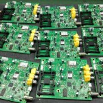
I would like to ask for your input on new machines or technologies that you are considering or have already committed to in your facilities.
Are you looking for higher feeder capacity machines to reduce the changeover time from product to product or group to group? Are you looking for a surface mount technology one stop solution line which provides you $50k per month and mix production on monthly basis? Are you still using old technological Surface mount Technology machines?

Southern Machinery provides many different types of products, especially across different types of machines, then please let me know also as we have solutions for these challenges too. To know more please click.
http://www.smthelp.net/advanced-pcb-assembly-machines-and-spare-parts/
http://www.smthelp.net/smt-high-quality-automatic-dip-soldering-machine/
http://www.smthelp.net/benefits-of-smt-tht-pcba-manual-to-auto-insertion/

Thank You !