CONTROL SYSTEM DESIGN OF SMT PICK AND PLACE MACHINE “

“CONTROL SYSTEM DESIGN OF SMT PICK AND PLACE MACHINE “

Here we would like to discuss original design of control system of complete SMT Pick and Place machine.

Proposed Design

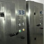
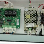
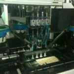
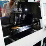
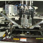
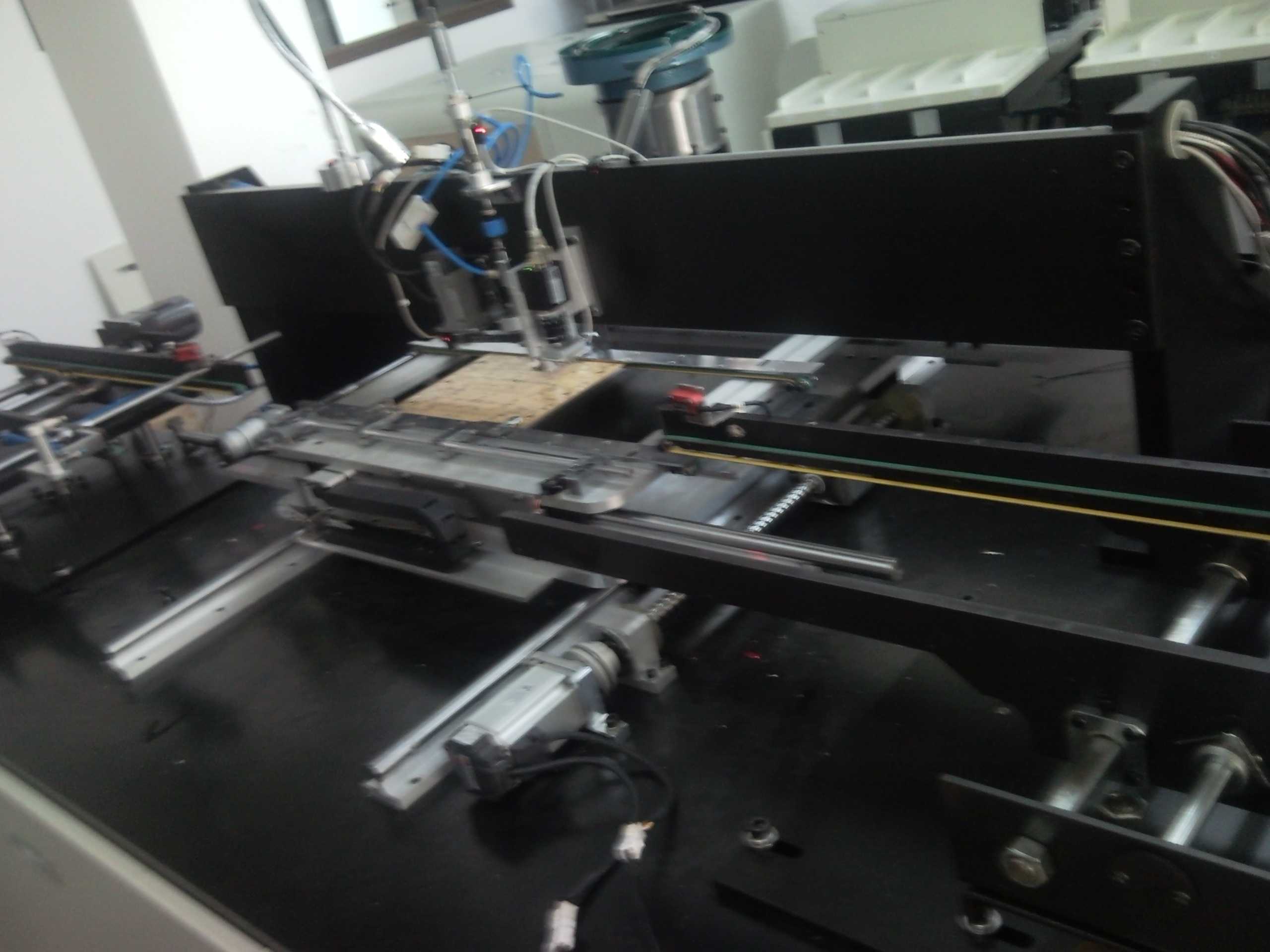
Southern Machinery Provide different type of SMT Pick and Place Machines according to the requirements and Specification of Global Clients however one of our machine consists of four DC motors. Three of these motors are used to move machine head along X-axis, Y-axis and Z-axis. Fourth motor is for rotating SMT component clockwise and anticlockwise. Encoders are attached to shafts of all four motors. These motors are connected to motor drivers through electric connections. Encoder outputs routed to the EISA card mounted on EISA port. Data bus from EISA card is attached to external main board. Motor drive cards are mounted on main board. In addition to different signals for actuating different relays, data bus also carry control voltage signals. These analogue voltage signals vary in the range from +5V _-5V. Duty cycle of PWM signal vary with changing magnitude of this analogue signal.

Main Board

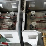
This is the part of our machines control system which acts as a bridge between EISA card and machines motors and feeders. All data signals and control voltage signals from EISA control card terminate at the main board. Depending on purpose which it serves, main board has several main parts. These parts are discussed here one by one.

Power Module

· This part of main board is associated with rectifying input AC voltage to DC voltage as shown in figure 5.1. Main functions of this part are following:
· Supply Power to motor drivers at 35v
· Supply 12V for powering operational amplifiers ICs. Supply 5V for powering TTL logic ICs.
· Supply 15V for actuating feeder plungers as shown in picture.

Protection Module
· This part contains relay switches to turn AC power on or off from software control as shown in picture.

Limit Switch Module
· This part deals with providing power source to proximity switches and receiving output of proximity or limit switches as shown in picture

Data Transmission Module
· This module receives data from some external data source through any programmable protocol (RS232 etc.) and routs that data to EISA card as shown in picture.

Feeder Relay Module
· This module consists of 15 relays. These relays actuate respective feeder plunger when decoded data is received. Each rely is connected with single plunger thus it controls one feeder at time as shown in picture.

Decoder Module
· This module receives 4 bit data from EISA card and decodes this data to 16 bits. 15 bits of decoded data are used to actuate one feeder at time as show in picture.
PWM Generation Module

· This part consists of two PIC18F2431 microcontrollers. These microcontrollers receive analogue control voltages and generate PWM. Microcontrollers are programmed such a way that duty cycle of PWM is function of input control voltage.
Motor Drivers

· Motor driver used in our project are H Bridge Bipolar type drivers. Input signal to motor driver are either bipolar PWM or analogue control voltage as show in figure
· 5.8. Motor driver use two kinds of power sources. One source is for driving motor
· when bridge is in conducting state. Motor driver receive 35V from main board for this purpose. Motor driver receive isolation supply from external transformers rated for 10V at output as shown in figure 5.9. This isolation supply voltage is rectified to DC voltage.
BENEFITS OF SMT THT PCBA MANUAL TO AUTO INSERTION

[tag smt,pcb,pcba,led]

BENEFITS OF SMT THT PCBA MANUAL TO AUTO INSERTION

Southern Machinery is affianced in supplying a wide range of PCB Assembly Equipments/Conveyors that is fabricated using high grade material, procured from quality conscious vendors. We are continually reinvests in the very latest technology and equipment based on customer demands and industry trends. Our Machines are widely acclaimed for easy adjustment, Low maintenance and high operational efficiency.

SOME OF BENEFITS FROM MANUAL TO AUTO INSERTION ARE STATED BELOW :
Decreasing labor cost
Predictable Product Quality – Less repairs
No wrong parts nor wrong polarity
Less risk of damage due to human contact (contamination, ESD, physical damage to components)
Easier manufacturing and operational Managment
Better clinching, less risk of solder issues.
Smaller factory space required to produce same volume of product
Decreased volume of inventory
Decreased Work in Process
Increased Inventory Turns
Quicker Product Change Over:
Less training • Fast product changeover
High Volume and High Mix capability
Decreased Energy Costs:
Low lighting and heating cost
Increasing labor costs make automation more attractive
As labor costs increase, the financial barrier to automation decreases, in many cases, becomes financially advantages.
Machines don’t require breaks, can run nearly continuously for fully automatic equipment, don’t call in sick, or quit.
Less management with reduced numbers of people.

Improved quality in the product
Less repairs/bad product due to wrong parts or wrong polarity.
Less risk of damage due to human contact (contamination, ESD, physical damage to components).
Significantly better clinching, less risk of solder issues.

Smaller factory space required to produce same volume of product
One machine can replace dozens of workers that require two or three times the factory space.
Allows customer to increase business without increasing factory space requirements.

Decreased Energy Costs:
Less lighting and heating costs / volume of product versus a factory large enough to house enough manual labor to produce the same volume.

Decreased Inventory:
Decreased volume of inventory
Decreased WIP
Increased Inventory Turns

Quicker Product Change Over:
Lines of people require training, changes in parts stock on line, more likely to keep the line dedicated.
Machines can change product in minutes, or accept engineering changes without training
Recommendations :

Use the Through Hole Design Guidelines to Teach :

How to specify a PCB able to be run with AI machines
Proper definition and selection of Tape and Reel or Ammo Pack components
Use the THDG as a way to provide “missionary” sales work for new customers
Make a Written Plan, using the Sales Checklist
Use the Sales Checklist
Create an RFQ to share and log the advance you get with the Applications Engineer and Product Team Manager, to get help in case special components, special boards, or special tooling Remember:
Remember :

Most Customers appreciate you show and teach them how to be self sufficient when selecting machines. This also helps to create trust.
Creating Trust will improve Customer relationships and eventually turn into business for you.

ADVANCED PCB ASSEMBLY MACHINES AND SPARE PARTS

ADVANCED PCB ASSEMBLY MACHINES AND SPARE PARTS

Southern Machinery is affianced in supplying a wide range of PCB Assembly Equipments/Conveyors that is fabricated using high grade material, procured from quality conscious vendors. We are continually reinvests in the very latest technology and equipment based on customer demands and industry trends. Our Machines are widely acclaimed for easy adjustment, Low maintenance and high operational efficiency.

· WE DELIVER SMT/AI MACHINES TO OUR WORLD WIDE CLIENTS :
Surface Mount Paste Printing Machines
Surface Mount Placement Machines
Surface Mount Reflow
Auto Insertion Machines advanced Technology
Solder Station
Cleaning equipment
Laser Cutter
Special UIC/TDK/PANASONIC/SCIENCGO SPARE PARTS ………..

Some of Our Products are still in operation in different countries of the World.

Machines / Equipment
Make & Models
1.Automatic Loader
Southern Machinery / SLD- 400B
2.Buffer Conveyor
Southern Machinery / S – 350C
3. Automatic Screen Printer

Southern Machinery / SP – 1008
4.Pick & Place
Southern Machinery / S-600L
5.Pick & Place
Southern Machinery / S-1200-LV
6. Pick & Place Machine
Southern Machinery / S-320
7.LED High Speed Pick And Place

Southern Machinery / S-K100
8.SCRAP TAPE CUTTER

Southern Machinery
9. Lead Free Reflow Oven
Southern Machinery / S-6600
10.Lead Free Reflow Oven S-6600-PC
Southern Machinery / S-600-PC

11. Pneumatic Stencil Cleaner Machine

Southern Machinery

12. Automatic dip soldering machine

Southern Machinery / S-DS300
13. Radial Insertion Machine

Southern Machinery / S3000
14.Axial Auto Insertion Machine

Southern Machinery / S4000
15.Odd Form Inserter
Southern Machinery / S-7000I
16.Wave Solder Machine
Southern Machinery / S-WS250
17.Auto-Dip Soldering machine

Southern Machinery / S-500S
18.Automatic Spray Fluxing System
Southern Machinery
19.Shuttle conveyor -to merger production line 2 in 1
Southern Machinery / S8300
20.Solder Chip FEEDER

Southern Machinery
21. SMT Feeder Calibration jig
Southern Machinery
22.Desktop Pick & Place

Southern Machinery / S-48V
23.Vibrating Feeder -for LED lens
Southern Machinery
24. Solder Paste Mixer
Southern Machinery
25. N2 Dry Cabinet

Southern Machinery
26.Pneumatic Stencil Cleaner Machine

Southern Machinery / S-1688

SMT HIGH QUALITY AUTOMATIC DIP SOLDERING MACHINE

SMT HIGH QUALITY AUTOMATIC DIP SOLDERING MACHINE

We hold an expertise in manufacturing a wide range of Dip Soldering Machine. Our range includes Dip soldering machine, automatic DIP soldering system, integrated automatic Dip soldering system and Integrated Automatic Dip Soldering System, which is manufactured using quality material. These provide to the requirements of various industries and are offered in various technical specifications to our clients. Southern Machinery – A leading name for the quality assurance of SMT/THT Machines worldwide.

Solder Paste and Its Application in SMT
Solder paste or solder cream is simply a suspension of fine solder particles in a flux vehicle. In electronics industry, solder paste is used in Surface Mount Technology (SMT) to solder SMDs on to the Printed Circuit board. The composition of the particles can be tailored to produce a paste of the desired melting range. Additional metals can be added to change paste compositions for specialized applications. Particle size and shape, metal content and flux type can be varied to produce pastes to varying viscosity.
Solder Paste Screen Printer
Some of the major features to consider when selecting screen printer for solder paste are the maximum size of the circuit board that can be handled, controls of accurate screen alignment and repeat ability of print, and the board hold-down mechanism. Considerable progress has been solder paste dispenser, screening and stenciling for pastes on substrates. Each method of dispensing solder paste has its own pros and cons but the most widely used method is stenciling for both rework and large scale production. Southern Machinery is a well-known supplier of screen printing equipment.

Stencils for Solder Paste Application
There are three main ways of making stencils for solder paste:
Chemical etching
Laser cutting
Electroforming
Chemical etching is the oldest, most widely used, and least expensive option. Laser cutting and electroforming, especially the latter, find appeal in applications where precision is paramount. In addition to the type of stencil, the type of squeegee blade is very important. Metal blade squeegees are widely used because they require less maintenance than rubber squeegees.
Availability of Solder Paste
Solder paste is available in both leaded (with lead) and lead-free (with no lead) forms. It can be no-clean or water soluble. With no-clean solder paste, there is not need to clean the board after soldering. Water soluble solder paste is easily soluble in water with no harm.
S-DS300Automatic dip solderingmachine

Specification :
Model
S-DS300
PCB width
Max.50~300mm(The longest support 350MM)
Transportation height
750±20mm
Transportation speed
0~1.8M/Min
Transportation Angle (Welding Angle)
0~7 degree
Transportation direction
From L to R
Component height limit
Max.80mm
Maximum capacity
250Pcs/hour
Dip soldering area
350X300MM
Preheating zone length
350mm(Stay – can set the preheating time)
Preheating zone number
1
Preheating zone power
2.1kw
Preheating zone temperature
Room temperature~250℃(Can be set up)
Heating mode
Far infrared
The power of the stove
7.2kw
"Tin stove dissolve tin amount
85KG
"Tin stove temperature
Room temperature~350℃、Control precision ±1℃
Temperature control mode
P.I.D+SSR
Machine control mode
Touch screen +PLC
Flux capacity
3L
Spray way
Import shower
power supply
3 phase 5 wire 380V
Starting power
10kw

Happy Chinese New Year

Chinese New Year is coming, and you’re probably thinking about the delicious homemade food, relaxing afternoon naps, and great time with friends and family. Don’t let these illusions blind you, though. You are walking into the apocalypse, and no one is on your side.

1. The Two-Faced Parents
For the first two days at home you’ll be their sweet baby, and starting from the third day they want to throw you away. You wake up at 9 and they say you are lazy. You wear ripped jeans and they say you are dirty. You eat too little then you are not giving them “face”. You eat too much then they say you are fat and will be single forever. There’s no chance of winning to argue with your parents. The only advice that could possibly help is to just wait – wait until you become a parent and take revenge on your own kids.

2. The Drama Queen Aunties
“How much money do you make now?” "Why are you still not married?” "When are you buying a house in Beijing?” Boom boom boom – drama queen aunties just released a trifecta. “My son got the 2nd place in the final!” “My daughter married a government official!” “I am having a grandchild in a month!” Whoops – drama queen aunties unlocked the advanced attack – kid comparison, it’s a killer. It’d be stupid to take it head on, but you can out-flank by dropping another drama bomb:“My mama don’t like you and she likes everyone.”

3. The CNY Friends
The CNY friends are those people who you are only friends with during Chinese New Year. However, they never come with good intention. “Hi how are you! Btw my wedding is next Monday.” Hand in ¥600. “How have you been? Oh right, it’s my baby’s 100-day ceremony tomorrow.” Hand in ¥800. “Long time no see! What a good timing that it’s my husband’s funeral today!” Hand in ¥1000. Are they the CNY friends, or CN¥ friends? The only way to get away from them is to go on the offense. Spread the rumor that you are diagnosed with brain cancer and are looking for friends to borrow money from. It will make them disappear.

4. The Annoying Kids
Eating up your favorite snack, drawing a penis on your expensive bag, and screaming at you for red pocket money – the annoying kids seem to be always high on ecstasy. Don’t even try to complain, otherwise they bring in the drama queen aunties to help:"He is just a kid! You are an adult! You are supposed to take care of him!" Well played, kids and aunties. The proper way to deal with annoying kids is to deal with them like the stupid hot girl at the party: you give them a lot of tasty alcohol and take them to bed – they won’t know a thing.

Thanks for reading this article, and hope you have an amazing holiday whether you are sipping cocktails by the beach, or playing MaJiang and chain smoking at home.

Low Budget S-EF 30000 Semi Automatic SMT Pick & Place Machine for LED lighting

"Low Budget S-EF 30000 Semi Automatic SMT Pick & Place Machine"

Southern Machinery supply SMT/AI competitively priced machines world wide & proud to release S-EF 30000 Semi Automatic SMT pick and Place Machine, to the Global Market. Designed and manufactured in ShenZhen China by Southern Machinery. S-EF 30000 is one of the most economical and cost effective Surface Mount assembly solution available in the market today. It is ideally suited for Led Lighting SMT assembly.
Southern Machinery has proven upper – class , with over hundreds of machines in operation around the world. We look forward to discussing your requirements.
i.mail.qq.comcid:3ADF7855@AC6FCA2F.6964B456

Features :
High-accuracy: Each of the eight pick up heads is equipped with a vision alignment camera to guarantee high accuracy. Using high resolution digital camera for fiducially recognition and programming.
High-speed: Maximum placement speed reaching 0.1s/chip.
Places SMD components from 0603 to 7474, including resistors, capacitors, standard and irregularly sha ped LEDs.
Suitable for all LED lighting products, including flexible PCB strips, circular LED light bulb boards and even irregularly shaped boards. Assembles LED PCBs up to 1.2 meters long in a single https://adderalloral.com pass.
Using motor-driven feeders for longer feeder life and higher speed under around-the-
clock production conditions.
Excellent quality hardware support by using international famous brands ensure placement repeatability and precision.
Self-developed software simplifies production, easy operating and programming.
Specification and Machine Parameters :
Model
S-EF30000
Alignment
Fixed Vision Alignment System
Number of Spindles
8 Spindles x 1 Gantry
Placement Speed (Practical)
Vision Alignment
LED 2835 27,000 CPH (Optimum)
LED 2835 29,500 CPH (Optimum)
Placement Accuracy
±0.1mm
(Based on the standard chips)
Component Range
Vision Alignment
0603(inch)~7474(mm), IC<15mm
Max Height
H=6mm
Board Dimension(mm)
Maximum
1,200(L) x 310(W)
PCB Thickness
0.5 – 3.0
Tape Feeder
Feeder Type
Motorized Feeder
Feeder Capacity
16 (12mm)
Optional
8mm, 12mm, 16mm, 24mm
Utility
Power
AC 220V ±10%
(50Hz, Single phase)
Max 2.2KW
Air Consumption
0.55-0.7MPa (5.6-7.1kgf/cm2)
Mass
Approx. 950kg
External Dimension(mm)
2,000(L) x 1,150(D) x 1,350(H)

Advantages of Motorized Feeder :
Higher feeding stability, effectively prevent pick-up failure.
Longer feeder life, hard to break down.
Motor-driven, save air source.
Higher feeding accuracy and consistency.
Higher feeding speed.
Intelligent adjustment of the feeding pitch.
Excellent Quality Hardware Support :
Ball Screws
KU RODA (Japan)
Servo Motors & Drivers
PA NASONIC (Japan)
Stepper Motors & Drivers
SHI NANO (Japan)
Vacuum System
From Taiwan
Negotiate Pressure Detecting System
KITA (Taiwan)
Cables
IGUS (Germany)
Operation
I PC

Working Efficiency:
Real Speed: 25,000-30,000 CPH
PCB Length: 1220mm / 4Ft
i.mail.qq.comcid:40BBB7A6@A7C5426A.6964B456
i.mail.qq.comcid:41BEF331@4510AE3A.6964B456
i.mail.qq.comcid:046B1E83@C36FE75E.6964B456

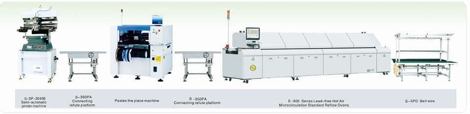
•Semi-Auto Screen Printer
•Semi-Auto Pick and Place MID END LED
•Buffer Conveyor LAMP SMT LINE
•Reflow Oven
•Worktable
i.mail.qq.comcid:E252AE82@27388E2C.6964B456

LOW COST SMT PRODUCTION LINES FROM SOUTHERN MACHINERY

"LOW COST SMT PRODUCTION LINES FROM SOUTHERN MACHINERY "

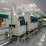
We have been supplying surface mount assembly equipment to worldwide market since 2011, and they continue to represent excellent value, ideal for small batches and prototypes as well as for medium volume SMT assembly.
Southern Machinery have small footprint, competitively priced machines for screen printing, SMT automatic pick and placement and re-flow Oven. There are many satisfied Countries like Kingdom of Saudi Arabia, India, Brazil, Egypt, Thailand and Pakistan users and full support from SOUTHERN MACHINERY Production Equipment is assured.
i.mail.qq.comcid:B90A5EE3@0F14180D.654BB356
i.mail.qq.comcid:89BDD278@5605F745.654BB356

Industrial Ultrasonic Cleaner cleaner for smt nozzle,PCB, stencil cleaning

Product Description

HTB1VEnvKFXXXXc8XXXXq6xXFXXX4.jpg

Specifications
1.Industrial Ultrasonic Cleaner
2.digital control timer
3.top quality steel made
4.digital LCD display
5.quality warranty
Industrial Ultrasonic Cleaner
Features
>Isolated-Circuit Design, Keep Water Away for Extra Safety
>Wide-Diameter Transducer for Best Cleaning Result
>Professional Design
>Powerful transducer and clear circut
>Top quality steel made for body,cover and base
>Digital LCD display leading fashion of the model Time setting,real time count-down,heation function,temperature control,live temperature display.easy operation
>Basdet and Tray Anti-noisy and Shock absorption Handle Drain Sophisticated made and customized design
>Professional testing,quality assurance
>Sophisticated design/fabulous outlook
>Digital control Timer Heating Temperature control function
Applications
Electronic factory
Jewelry factory
Chemical lab
Dental clinic
Restaurant
Repair shop
Family, etc
Specification
Ultrasonic Frequency
40000 Hz
Tank Material
Stainless Steel SUS304
Tank Capacity
3.2L
Timer
1-30 Minutes, Digital timer
Power Supply
AC 100 – 120V, 50 / 60 Hz
AC 220 – 240V, 50 / 60 Hz
Ultrasonic Power
120W
Heating Power
100W, Digital heating
Unit Size
270 X 170 X 240 MM ( L x W x H)
Tank Size
240 X 135 X 100 MM ( L x W x H)
Package Size
330 X 250 X 310 MM ( L x W x H)
N.W.
3.8 KG
G.W.
4.1 KG
Shipping Information:
Carton size (12 pcs)
775 X 685 X 320 mm(L x W x H)
Carton gross weight (12 pcs)
25 kg
Cube( 12 pcs)
0.18 M3
20` Container capacity
1980 pcs
40` Container capacity
2280 pcs
40` High container capacity
3216 pcs

PCBA Quality Process Audit — SMT Pick and Place machine

1. Work Instructions
1.1 Is there a revision controlled Operator Work Instruction which contains loading information for the specific product being built? (Score 0 if any unsigned/undated handwritten instructions or any handwritten instructions more than 48 hrs old)
1.2 Are Work Instructions readily available to the operator and are they followed at Component Placement?
1.3 Are component part numbers and descriptions included on the Work Instructions?
1.4 Are component descriptions sufficiently detailed to check at first-article that the correct components are being used?
1.5 Is the machine head/slot number for component loading specified for each part number on Work Instructions?
1.6 Are the reference designators and the quantity per part number specified on Work Instructions?
1.7 Is the component feeder type/size specified on Work Instructions or otherwise for each component package type?
1.8 Is the machine Program Name specified on the Work Instruction or line set-up instructions?
2. Component Loading and Verification
2.1 Is there an automated bar coded component loading verification aid in order to reduce the probability of incorrect loading? Note*
2.2 Are the component loading verification aids hard linked to the placement program so that loading is verified against program data?
2.3 Can traceability of component lot codes be demonstrated for critical devices?
2.4 Is component loading/changes verified and cross checked by an individual other than the set-up operator at product changeover? Note*
2.5 Is a component loading/changes verification log signed by the set-up operator and countersigned by the cross checker before start up? Note*
2.6 Is the correct feeder loading base used to facilitate real to feeder loading?
2.7 Are first-built boards verified against documentation for missing/misplaced components and for correct component polarity?
2.8 Are first-articles conducted using AOI methods and complemented with description verification and value metering?
2.9 Are all Resistors & Capacitors measured for a value within the tolerance (one per part number) at first-article & at reel change?
2.10 Is a first-article log signed to verify acceptance before start up?
2.11 Is the orientation of Tantalum SMT capacitors, Diodes, etc in tape format, standardized and documented for polarity orientation?
2.12 Is the IC tray loading polarity standardized for each type of polarity indicator that can be used for each component?
2.13 Is loading polarity referenced both from the tray and the component so as to ensure retrayed components are correctly loaded?
3. Nozzles, Feeders, and Tooling
3.1 Is there a document which details the standardized nozzle diameter set-up selected for each type of placement equipment?
3.2 Are these standardized nozzle diameter set-up documents readily available for when nozzles need to be replaced or changed?
3.3 Is there a document which details the range of component XYZ body sizes that each selected nozzle type can successfully place?
3.4 Is there a documented requirement to conduct daily nozzle centering and is there evidence that this is done?
3.5 Is each feeder identified with its own unique serial number?
3.6 Is there a documented and effective Feeder Maintenance Program? Records (s/w or otherwise) must be by Feeder Serial Number.
3.7 Are database records maintained for each feeder serial number for the purpose of tracking its maintenance history and performance?
3.8 Is feeder maintenance history used to monitor feeder life so that problematic feeders can be removed from the process?
3.9 Can it be demonstrated that the number of feeder indexes is counted & monitored for each unique feeder using software or otherwise?
3.10 Is this information used to flag that feeder preventative maintenance is required after x number of indexes?
3.11 Is there a documented requirement to indicate that Blocks or Support Pins are needed for specific products?
3.12 Is the No, location, type and height of Support Blocks/Pins identified on a product by product basis? Score NA if in 3.11 there are not needed.
3.13 Are the Support Pin locations identified for each product using templates/tooling or some other effective solution? Comment as above.
4. Moisture Sensitive Devices
4.1 Are components stored before loading and after unloading in a manner which prevents damage?
4.2 Are the Moisture Sensitive Devices (MSDs) and their sensitivity level readily known to the operator?
4.3 Are MSDs time stamped at opening and their exposure time monitored against pre determined limits?
4.4 Is there a flag to indicate that the exposure time has been exceed for any given device in a dry box?
4.5 Is there a flag to indicate the MSD exposure has expired for any MSD device currently loaded in the placement machines?
4.6 Have MSD procedures been updated to reflect the JEDEC standard for MSD control? (J-STD-033A MSD released in July 2002)
4.7 Is there evidence of correct implementation of J-STD-0033A for all MSD devices?
4.8 Are there MSD procedures in place to ensure MSD shelf life is reduced based on measured Relative Humidity conditions?
4.9 Is there a method in place to address the time spent in dry storage and its effect on remaining life based on MS Level and RH Level?
4.10 Is it clearly understood that MSD ‘shelf life’ continues to degrade during dry cabinet storage of some MSD devices?
4.11 If MSDs are on both sides of a PCBA, is there an effective method to account for time between 1st and 2nd reflow?
4.12 Can MSD control be demonstrated for MSD devices that need internal/external pre-programming?
4.13 Can MSD control be demonstrated for rejected devices and devices used for rework?
4.14 Have MSD recovery methods been defined and adequate for all component types?
4.15 Does the control of Moisture Sensitive Components include those components on reels?
4.16 Is the baking or hot room storage time and temperature documented and controlled for component recovery?
4.17 Has this time and temp been determined based on the component supplier’s guidelines / J-STD-0033A?
4.18 Is there evidence to demonstrate that the control process for MSDs is in use and is effective?
5. Machine Capability
5.1 Are Component Placement Programs generated from CAD XY coordinate data?
5.2 Is there a standardized nomenclature for Shape Code definition?
5.3 Can this nomenclature be used to determine the most appropriate shape code to allocate to a given part of given dimensions?
5.4 Are localized fiducials used for fine pitch devices when localized component fiducials exist on the board?
5.5 Has manual component moving been eliminated given correct CAD, nozzle set-up, Shape Code allocation, local fiducials, Cam speed, etc?
5.6 Does the Fine Pitch placement machine have the capability to check lead Coplanarity in xyz?
5.7 Does the Fine Pitch placement machine use its coplanarity capability on all leads of 20 mil pitch or less, and all programmed parts?
5.8 Does the Fine Pitch placement machine have the capability to check ball arrays? If no such device, score NA.
5.9 Does the Fine Pitch placement machine use its ball array verification capability for all BGA devices? If no such device, score NA.
5.10 Is the machine Program Name revision controlled to show traceability of program changes?
5.11 Is the machine Program Name traceable to the PWB and PCBA part number?
6. PCBA
6.1 Are outputted boards at least sample inspected pre reflow for placement positional accuracy for machine control purposes?
6.2 Is the frequency for this verification defined and documented, and is there evidence to suggest it is followed?
6.3 Is there a visual aid available which identifies the populated locations with polarity, and also the no-pop locations?
6.4 Is there a placement standard pre reflow to validate placement accuracy for the shape code, nozzle allocation, etc. parameters used?
6.5 Is there evidence to demonstrate that action is taken to adjust the machines performance for when this standard is exceeded?
7. Attrition Rates and Rejected Components
7.1 Is attrition rate monitoring conducted systematically to ensure feeder and/or nozzle problems are captured at least hourly?
7.2 Is there documented evidence to ensure attrition rates are checked and actioned at least hourly to ensure process control?
7.3 Is there a specification defined for acceptable attrition rates for the individual feeders?
7.4 Is there a specification defined for the maximum allowable number of nozzle skips per machine before it is shut down for repair?
7.5 Are these specifications determined based on a percentage combined with the number of placements for a given time period?
7.6 Is there evidence to demonstrate that attrition rate monitoring is conducted, effective, and used to make process control decisions?
7.7 Is there a documented process for the disposition or reuse of machine rejected components? Rs and Cs must not be reused even for rework.
7.8 Are rejected components reviewed and repaired to ensure conformance before reuse, even if only used for rework?
7.9 Are there repair blocks available or a lead conditioner in use for repairing ‘real’ Coplanarity rejects? Score 0 if parts not repaired.
7.10 Does the re-traying process always ensure that component polarity wrt the tray and the component loading polarity is preserved?
7.11 Is there a documented Process Deviation procedure to manage machine skips for hand placement if hand placement is allowed?
8. Process Capability
8.1 Has a Process Capability Analyses (PCA) been conducted and the Cpk acceptable for the suite of shape codes in use?
8.2 Were shape code allocations, component nozzle allocations, cam speeds, etc. recorded for this PCA?
8.3 Are the recorded shape code allocations, component nozzle allocations, and cam speeds, the same as those used today?
AI spare parts、Universal Parts,UIC,TDK.VCD Sequencer.SMT,THT,PCB,PCBA,AI,wave soldering,reflow oven,nozzle,feeder,wave soldering,PCB Assembly, LED, LED lamp, LED display

2 video to compare manual and automatic component lead cutting for electronic manufacturing PCBA

SAVE YOUR TIME & SAVE YOUR MONEY
 
While decide to purchase SMT Pick and Place Machine ! 
 
let us instruct you and provide you complete suitable SMT/THT machines according to your choice and requirements with a comprehensive Buyers’s Guide to save your time and Money. To search Out for your company’ which Pick and Place machine is best suited to your production needs – and your Budget. 
 
Southern Machinery Helps you : 
  • Identify your production requirements and your needs. 
  • Make sense of your equipment specifications. 
  • Calculate your speed and feeder needs. 
  • Create equipment benchmarks and apple to apple comparison of models and brands. 
  • Provides machines and spare parts according to your choice and specifications with a comprehensive Buyers Guide. 
  • Short time delivery period with affordable price. 
  • Training on site from 20- years expert team.
  • Many more ………………..


Electronic component lead cutting by Manual

Automatic Electronic component lead cutting


AI spare parts、Universal Parts,UIC,TDK.VCD Sequencer.SMT,THT,PCB,PCBA,AI,wave soldering,reflow oven,nozzle,feeder,wave soldering,PCB Assembly, LED, LED lamp, LED display

2 video to compare Manual and Auto PIN/ Eyelet/Terminal insertion for electronic manufacturing PCBA

The Through Hole Assembly, also known as thru hole assembly, process uses the latest models with the quickest possible turnaround rate in the industry. Assembling excellent stable sequencing performance with easy operating software utilizing its high precision through hole assembly both by hand and automation to create electronic solder connections.


C (20121106 212843894) Audio003

Automatic PIN/ Eyelet/Terminal insertion:

ManualPIN/ Eyelet/Terminal insertion:

AI spare parts、Universal Parts,UIC,TDK.VCD Sequencer.SMT,THT,PCB,PCBA,AI,wave soldering,reflow oven,nozzle,feeder,wave soldering,PCB Assembly, LED, LED lamp, LED display

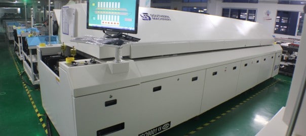
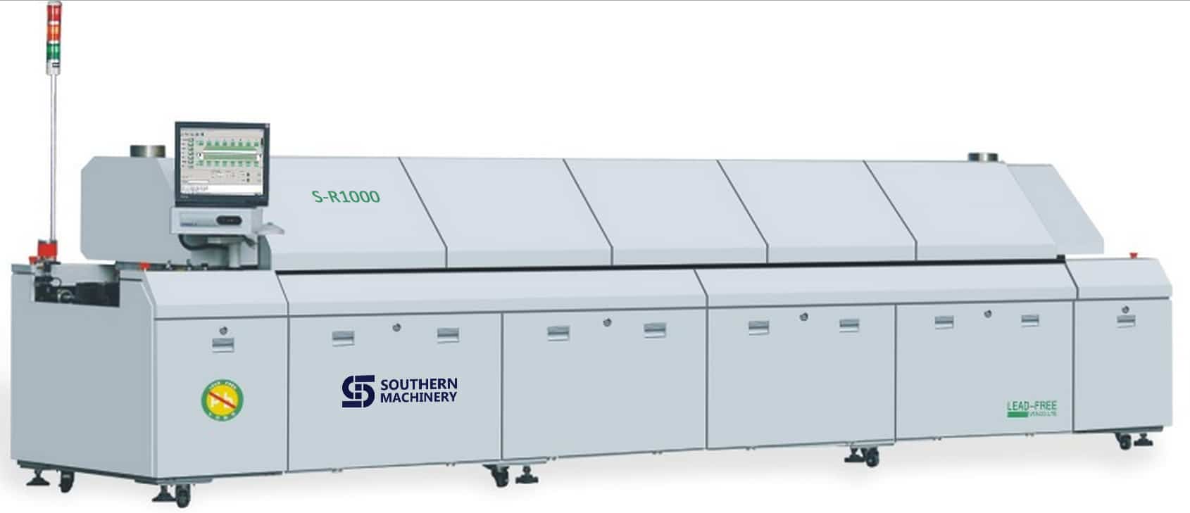
SMT Lead-Free Reflow Over S-R1000 for electronic manufacturing PCB assembly

AI spare parts、Universal Parts,UIC,TDK.VCD Sequencer.SMT,THT,PCB,PCBA,AI,wave soldering,reflow oven,nozzle,feeder,wave soldering,PCB Assembly, LED, LED lamp, LED display

CatchBDD7(02-01-(02-01-11-12-19)


Features:

1.Control System: PC + Siemens PLC control system,accurate temperature control and more stable,ensures temperature stability rate to be more than 99.99%.

2.Hot air system: first-class heating module, the best temperature zone interval design makes optimum temperature uniformity and repeat.The effective utilization and thermal compensation efficiency,it needs less than 20 minutes from temperature control accuracy ± 1 ℃ ambient temperature to a temperature stabilization .

3.Monitoring Software:Windows interface, traditional and simplified Chinese and English online free switch, and operator password management, easy to operate.Operation records, temperature curve measurement and analysis functions, virtual simulation, fault self-diagnosis, process monitoring, automatic generate and save process control documents, substrate transport dynamic display.

4.Cooling System: new cooling zone, quick and easy adjustment, easily reach the cooling requirements of different slopes.

5.Temperature protection: using third-party over-temperature protection, multiple layers protection to ensure safe operation.

6.Products comply with CE, CCC, UL , other standards and specifications.

7.User-friendly design: fault detection (such as heaters abnormal alarm, etc.), regular maintenance reminders, the economy functions and tool-free maintenance, reducing equipment failure rates.

8.Heating module: Transverse reflow design makes temperature from each zone is not influenced by neibour to ensure accurate temperature curve, while ensuring a high production capacity and heat exchange capacity to achieve high adaptability (to meet the soldering of automotive, communications, electronics, computers and mobile phones consumer electronics.)

9.Hot air motor with independently inverter controlled, set operating frequencies depending on different technology to meet a variety of lead-free processes.

10. Machine using zero gas source design, furnace cover with motor lifting, safety rod support, providing significant security.

11.Main parts:Imported main parts ensure equipment runs smoothly and lower the maintenance cost.

12. Customers can choose optional flux processing system according to their own production features  to ensure furnace chamber clean.

13.Closed-loop transmission speed control systems, transportation accuracy ± 2mm / min, ensuring more stable transmission speed.

14.Central support, dual transmission, external water cooling system is optional.

TOP Advantage:

1.Simple: combined with advanced international concepts, based on the Oriental-designed operating system, easy to understand, easy to learn, easy to maintain.

2.Expertise: learn imported reflow oven’s advanced design concepts, and the machine core components are using imported top brands.

3.Hedging: Import hardware configuration,low failure rate in production,more than a decade service life.

4.Safety: Based on the general rules of international design, close to imported reflow rating, the highest security level.

5.Stable: mature software, hardware and top production processes ensures stability of each equipment.

Application  

Widely used in high precision products like 01005-QFP, BGA, CSP, Flip,and POP ,automotive electronics, mobile devices, home appliances, communications, LED, semiconductor and other industries.

Specification:


Southern Machinery  Reflow Oven Specifications
S – Standard, O – Option, M – Manual, A – Auto, N/A – Not Availible)
Specifications S-R800 S-R1000 Specifications E8 E10
Dimension (L*W*H)mm 5310x1353x1490 6100x1353x1490 Board Dropped Alarm S S
Standard Color Computer Grey Computer Grey Electrical SMEMA Interface S S
Weight Approx.2150KG Approx.2400KG Computer Lenovo Lenovo
Number Of Heating Zones Up8/Bottom8 Up10/Bottom10 Max.Width Of PCB 400mm 400mm
Length Of Heating Zones 3121mm 3891mm Temperature Deviation on PCB ± 1.0℃ ± 1.0℃
Rail Width Adjustment A and M(Multi mode) A and M(Multi mode) Max. Temp. Gap Between Preheat Zones Setting 40℃ 40℃
Rail Number 1 Lane or 2 Land 1 Lane or 2 Land Temperature Control Precision ± 1.0℃ ± 1.0℃
Exhaust Volume 10M3/minx2 Exhausts 10M3/minx2 Exhausts Conveyor Height 900+/-20mm 900+/-20mm
Control System PLC+Computer PLC+Computer Length Of Cooling Zones 600mm 600mm
Transmission Agent  Chain + Mesh  Chain + Mesh Center Support O O
Electric Supply Required 3phase,380V 50/60Hz 3phase,380V 50/60Hz Siemens PLC S S
Power For Warm Up 30KW 36KW Lubrication Auto-Afflux S S
Power Consumption 8KW 12KW Ups S S
Warming Time Approx.25 minute Approx.25 minute Temp. Thermocouple Slot S S
Temp. Setting Range Room Temp.– 300℃ Room Temp.– 300℃ Driven Top Hood Opening A A
Oil Supply A and M(Multi mode) A and M(Multi mode) Temperature Control Method PID + SSR S S
Conveyor Speed Range 300~2000mm/min 300~2000mm/min Number of Cooling Zones 2 2
Components Clearance Top/ Bottom is 25mm Top/ Bottom is 25mm On Line Editing S S
Conveyor Direction L→R (Option: R→L) L→R (Option: R→L) Max.Temp.Gap Between Preheat & Reflow Setting 80℃ 80℃
Commutated Element Aluminum Alloy Plate (8mm) Aluminum Alloy Plate (8mm) Max. Temp. Gap Between Reflow Zones Setting 50℃ 50℃
Fixed Rail Side Front Fixed  (Option:Rear  Fixed) Front Fixed  (Option:Rear  Fixed) Process Data & Status Storage S S
Cooling Method Forced-Air Motor and fan (Standard) Forced-Air Motor and fan   (Standard) Temperature Alarm S S


Independent Upper and Lower PID Temperature Controls

Independent Upper and Lower PID Temperature Controls for Each Heating Zone Permit Precise Temperature Profiling

S-R1000’s heating zone temperature controllers have an accuracy of ±1°C and, in conjunction with a high-speed blower adjacent to each heat source for maximum convection, ensure a ΔT of ±2°C across the PCB assembly. The Series diffuser design provides low-velocity, low-turbulence air flow to prevent component shift or disturbance.

Optional thermocouples can be attached at critical locations on the PCB and connected to three built-in inputs (standard) on the oven for communication with  control software for accurate, real-time temperature profiling to match any solder paste manufacturer’s specifications.

CR-10000 SMT Reflow Oven Pin over mesh conveyor

Pin-Over-Mesh Conveyor Meets Virtually Any Product Specification or Production Requirement

The S-R1000 is supplied as standard with an adjustable-rail, pin-type conveyor system that handles PCBs up to a maximum of 450 mm (17.7″) installed over a 570 mm (22″) stainless-steel mesh belt. The pin conveyor permits inline and double-sided processing. The mesh belt is ideal for fast changeovers.

To eliminate the possibility of jamming or dropped PCB assemblies, all components are constructed of high-quality, high-strength, stainless steel and are built to maintain dimensional tolerances at the high temperatures of lead-free processing.

Advanced automatic chain lubrication and motorized width adjustment are standard features on the pin conveyor. Automatic width adjustment of the pin conveyor, based on the parameter settings for specific reflow programs, is available as an option. For processing of larger PCBs at higher lead-free temperatures, a center support system is available to prevent board warpage.

Conveyor speed is programmable from 400-1800 mm (16″-71″) per minute to accommodate any process requirement.

Nitrogen Atmosphere Compatible Models Widen Lead-Free Processing Window Through Reduced Oxidation

While the debate over air or inert reflow atmospheres continues, as an option, offers the S-R1000 in a nitrogen-compatible configuration for manufacturers who want the flexibility for soldering in both environments.

Most experts agree that the reduction of oxygen through the introduction of an inert gas (usually N2) will allow a wider process window and provide better solder joints through reduced oxidation. The enhanced flow design of the heating chamber in the S-R1000 nitrogen compatible system lends itself to efficient heat transfer and ensures low nitrogen consumption while maintaining O2 levels between 300-1000 ppm.

CR-10000 reflow oven internal water-chilled recirculating cooling system available

Internal Water Cooling Provides Maximum Control Over Critical Cooling Rates Required By Some Lead-Free Solders

Because the higher liquidus temperatures required by lead-free solders approach the limits of many SMT components and PCB assemblies, more aggressive cooling is often required to reduce peak temperature exposure times. Some recent studies also indicate that cooling rates have a significant effect on solder joint grain structure.

For these reasons, an internal water-chilled recirculating cooling system is available for the S-R1000. It allows users to alter cooling rates to meet solder paste manufacturers recommendations to a much greater degree than is possible with the exclusive use of air cooling.

CR-10000 reflow oven real-time profiling

Advanced Functionality and Process Management Capability

Operation and control of all  reflow systems is accomplished through an attractive, colorful, visual user interface that features a full-screen, virtual view of the system with display of pre-set and actual zone temperatures, system status and conveyor speed.

The Windows-based operating system and control software includes advanced functions for temperature profiling, timed automatic startup and shutdown, audible and visual alarms, and password protection.

A PC-controller with 15″ flat screen monitor, keyboard and trackball allow unlimited storage and networking capability.

All systems employ UPS battery backup to ensure removal of all product from the oven in the event of a power outage.