This is our Radial Insertion machine offline software, you can learn how to program and operate the machine (password: smthelp.net) (engineer password: 123456 or 12345678)


This is our Radial Insertion machine offline software, you can learn how to program and operate the machine (password: smthelp.net) (engineer password: 123456 or 12345678)

Cut and Clinch Footprints
The cut and clinch cuts the component leads after they are inserted
through the PC board and then clinches them against the underside
of the PC board, securing the component in place.

Keyword guide: circuit board cleaning, circuit board cleaning, PCBA circuit board cleaning, PCBA circuit board cleaning, solvent cleaning agent, water-based cleaning agent, water-based cleaning technology
Before discussing the question of “why use water-based cleaners for PCBA circuit board cleaning”, let’s take a look at the advantages and disadvantages of solvent-based cleaners.

Organic solvent cleaning agents can be divided into flammable cleaning agents and non-flammable cleaning agents according to their safety performance. The former are mainly organic hydrocarbons, alcohols and esters, and the latter are mainly chlorinated hydrocarbons and fluorinated hydrocarbons. Its process characteristics are introduced as follows:
If we take advantage of the advantages and disadvantages of organic solvent cleaning and avoid the disadvantages, wouldn’t it be perfect? Is it feasible? The answer is yes! Water-based cleaners were born around solving this problem.
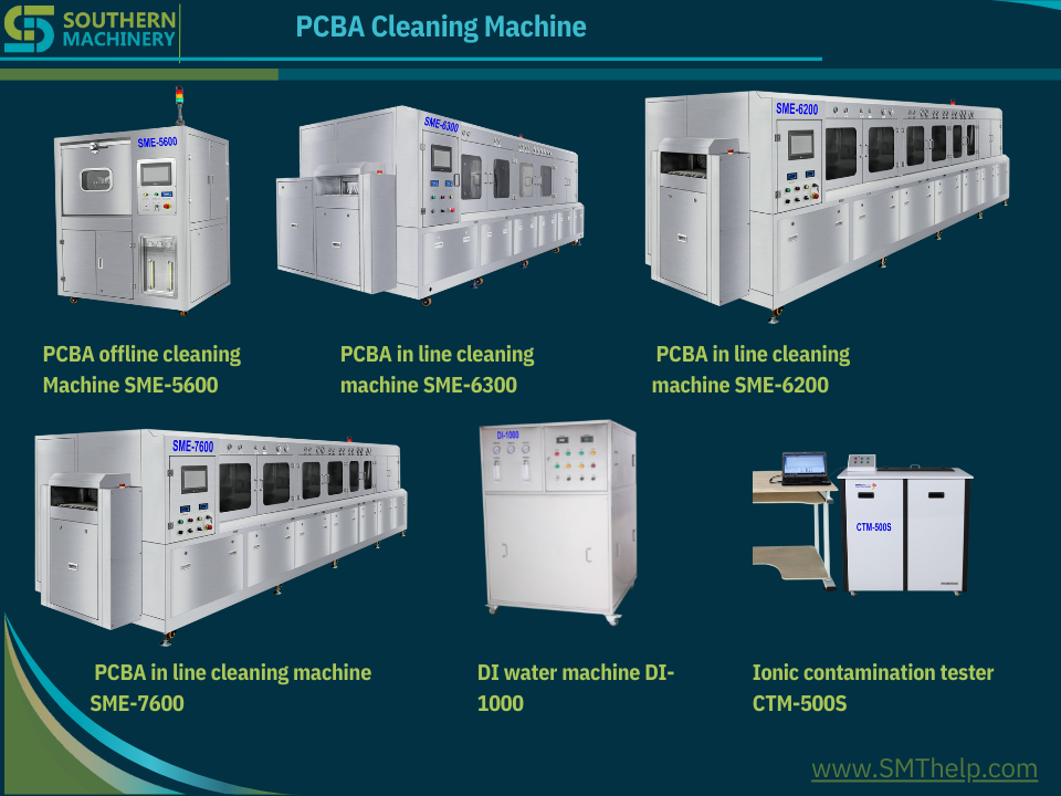
Water-based cleaning technology is made of water as the cleaning medium, and various additives such as surfactants, solvents, defoaming agents, and corrosion inhibitors are added, and various pollutants are removed through various mechanisms such as dissolution, adsorption, and infiltration.
The main features of the water cleaning process are non-flammable and explosive, non-toxic and environmentally friendly, safe in operation, strong in cleaning ability, low in loss during cleaning, and low in cost. Because of the large degree of freedom of active ingredients, the formula can be formulated according to the special requirements of PCBA, which solves many problems. The problems that cannot be solved by organic solvent cleaning agents have a wide cleaning range and strong applicability. The flexible components of water-based cleaning agents can greatly meet the needs of customers, especially when ultrasonic cleaning and spray cleaning are used, they are more advantageous than organic solvents. .
Of course, water-based cleaning agents also have shortcomings, such as high requirements for cleaning equipment, and the need to treat invalid cleaning agents, that is, waste water.
Combining the characteristics of solvent-based cleaning agents and water-based cleaning agents, it is not difficult to find that with the strengthening of safety and environmental protection awareness and the increase of special cleaning needs for PCBA, water-based cleaning agents stand out because of their flexible formulas and components, representing the future of PCBA cleaning. Technology development direction.
We understand that SMT machine training and after sales service are a key to choose a new supplier.
Please click below links to see machine 3D models:
https://www.smthelp.net/html/SMT Production line.html https://www.smthelp.net/html/THT_Auto_Insertion_full_line.html
SMT AI Peripheral Equipments and Spare parts
| Item | Product Name | URL |
| 1 | Bicycle | https://www.smthelp.net/html/Bicycle.html |
| 2 | FUJI_NXT_8mmfeeder | https://www.smthelp.net/html/FUJI_NXT_8mmfeeder.html |
| 3 | IC_tube_to_reeltapepackingmachine | https://www.smthelp.net/html/IC_tube_to_reeltapepackingmachine.html |
| 4 | PCBA_THT_fixture | https://www.smthelp.net/html/PCBA_THT_fixture.html |
| 5 | RS-1_Vibration_tube_FEEDER_BANK | https://www.smthelp.net/html/RS-1_Vibration_tube_FEEDER_BANK.html |
| 6 | SMT Label feeder.htm | https://www.smthelp.net/html/SMT Label feeder.htm |
| 7 | SMT reel tape feeder 72mm width | https://www.smthelp.net/html/SMT reel tape feeder 72mm width.html |
| 8 | SMT_axial_Radial_feeder_bank | https://www.smthelp.net/html/SMT_axial_Radial_feeder_bank.html |
| 9 | SMT_label_mounter | https://www.smthelp.net/html/SMT_label_mounter.html |
| 10 | SMT_Odd_Bowl_feeder | https://www.smthelp.net/html/SMT_Odd_Bowl_feeder.html |
| 11 | SMT_tray_feeder_B | https://www.smthelp.net/html/SMT_tray_feeder_B.html |
| 12 | SMThelp_PCBA-smt | https://www.smthelp.net/html/SMThelp_PCBA-smt.html |
| 13 | UIC_autoinsertion_Spareparts_list | https://www.smthelp.net/html/UIC_autoinsertion_Spareparts_list.html |
| 14 | wave_soldering_line | https://www.smthelp.net/html/wave_soldering_line.html |
| 15 | Wave soldering machine | https://www.smthelp.net/html/Wave soldering machine.html |
| 16 | Adapter JUKI Nozzle with Nozzle | https://www.smthelp.net/html/Adapter JUKI Nozzle with Nozzle.html |
| 17 | Auto Insertion Axial Radial Oddform Production line | https://www.smthelp.net/html/Auto Insertion Axial Radial Oddform Production line.html |
| 18 | Bowl Radial reel feeder w JUKI cart | https://www.smthelp.net/html/Bowl Radial reel feeder w JUKI cart.html |
| 19 | Conveyor 1M nolight | https://www.smthelp.net/html/Conveyor 1M nolight.html |
| 20 | Feeder cart-Bowl Axial Radial Tube | https://www.smthelp.net/html/Feeder cart-Bowl Axial Radial Tube.html |
| 21 | FUJI glue nozzle | https://www.smthelp.net/html/FUJI glue nozzle.html |
| 22 | FUJI nozzle WGW-CZ | https://www.smthelp.net/html/FUJI nozzle WGW-CZ.html |
| 23 | FUJI nozzle WJH-CZ | https://www.smthelp.net/html/FUJI nozzle WJH-CZ.html |
| 24 | fuji NXT 8mm feeder | https://www.smthelp.net/html/fuji NXT 8mm feeder.html |
| 25 | fuji NXT 8mm feeder | https://www.smthelp.net/html/fuji NXT 8mm feeder.html |
| 26 | FUJI Sfab Radial tape feeder | https://www.smthelp.net/html/FUJI Sfab Radial tape feeder.html |
| 27 | Gripper nozzle for E-cap | https://www.smthelp.net/html/Gripper nozzle for E-cap.html |
| 28 | Hign end conveyor 1M w PCBA | https://www.smthelp.net/html/Hign end conveyor 1M w PCBA.html |
| 29 | JUKI 2 layer bowl feeder w cart | https://www.smthelp.net/html/JUKI 2 layer bowl feeder w cart.html |
| 30 | JUKI Gripper_Nozzle 2583 C | https://www.smthelp.net/html/JUKI Gripper_Nozzle 2583 C.html |
| 31 | Juki Nozzle 500 Assembly | https://www.smthelp.net/html/Juki Nozzle 500 Assembly.html |
| 32 | Juki Nozzle 500 Head Assembly | https://www.smthelp.net/html/Juki Nozzle 500 Head Assembly.html |
| 33 | JUKI Radial tape feeder big span | https://www.smthelp.net/html/JUKI Radial tape feeder big span.html |
| 34 | JUKI Radial tape L lead feeder | https://www.smthelp.net/html/JUKI Radial tape L lead feeder .html |
| 35 | Juki2050 Feeder Cart w Radial axial | https://www.smthelp.net/html/Juki2050 Feeder Cart w Radial axial.html |
| 36 | Mobile charger PCBA | https://www.smthelp.net/html/Mobile charger PCBA.html |
| 37 | Nozzle adepter | https://www.smthelp.net/html/Nozzle adepter.html |
| 38 | Nozzle base | https://www.smthelp.net/html/Nozzle base.html |
| 39 | Odd form insertion Feeders w loader-unloader | https://www.smthelp.net/html/Odd form insertion Feeders w loader-unloader.html |
| 40 | Panasonic Al Spare parts list 2 | https://www.smthelp.net/html/Panasonic Al Spare parts list 2.html |
| 41 | Panasonic CM602 Bowl feeder | https://www.smthelp.net/html/Panasonic CM602 Bowl feeder.html |
| 42 | PCB Combo loader destacker+Magazine | https://www.smthelp.net/html/PCB Combo loader destacker+Magazine.html |
| 43 | PCB Magazine | https://www.smthelp.net/html/PCB Magazine.html |
| 44 | Power supplier | https://www.smthelp.net/html/Power supplier.html |
| 45 | Radial Cutter clinch head | https://www.smthelp.net/html/Radial Cutter clinch head.html |
| 46 | Radial Insertion Head Assy w Ecap | https://www.smthelp.net/html/Radial Insertion Head Assy w Ecap.html |
| 47 | RS-1 FEEDER BANK w Vibe tube feeder | https://www.smthelp.net/html/RS-1 FEEDER BANK w Vibe tube feeder.html |
| 48 | S3010A Radial Insertion machine inline | https://www.smthelp.net/html/S3010A Radial Insertion machine inline.html |
| 49 | S3010A Radial machine no cover | https://www.smthelp.net/html/S3010A Radial machine no cover.html |
| 50 | S7000 Odd Form Insertion machine | https://www.smthelp.net/html/S7000 Odd Form Insertion machine.html |
| 51 | S7000 Oddform insertion 3 bowl feeder | https://www.smthelp.net/html/S7000 Oddform insertion 3 bowl feeder.html |
| 52 | S700D Odd Form Insertion machine | https://www.smthelp.net/html/S700D Odd Form Insertion machine.html |
| 53 | S-7020T Terminal insertion | https://www.smthelp.net/html/S-7020T Terminal insertion.html |
| 54 | S-7040 Oddform insertion w 4 bowl feeder | https://www.smthelp.net/html/S-7040 Oddform insertion w 4 bowl feeder.html |
| 55 | S-7040T Oddform insertion w Tray feeder | https://www.smthelp.net/html/S-7040T Oddform insertion w Tray feeder.html |
| 56 | SBH250 NGOK dual nagazine PCB unloader w magazine | https://www.smthelp.net/html/SBH250 NGOK dual nagazine PCB unloader w magazine.html |
| 57 | SBU460 Bare PCB destacker loader +conveyor | https://www.smthelp.net/html/SBU460 Bare PCB destacker loader +conveyor.html |
| 58 | SLD250 PCB loader w magazine | https://www.smthelp.net/html/SLD250 PCB loader w magazine.html |
| 59 | SLD250 S4020A+S3010A SULD250 Al machine production line | https://www.smthelp.net/html/SLD250 S4020A+S3010A SULD250 Al machine production line.html |
| 60 | SLD250+ S3020A +SULD250 Radial Insertion machine inline | https://www.smthelp.net/html/SLD250+ S3020A +SULD250 Radial Insertion machine inline.html |
| 61 | SLD250+S3010A(s)+SULD250 Al machine production line | https://www.smthelp.net/html/SLD250+S3010A(s)+SULD250 Al machine production line.html |
| 62 | SLD250+S3010A+S7040T(tray feeder)+SULD250 Al machine production line | https://www.smthelp.net/html/SLD250+S3010A+S7040T(tray feeder)+SULD250 Al machine production line.html |
| 63 | SLD390 SMT PCB loader (L-R) | https://www.smthelp.net/html/SLD390 SMT PCB loader (L-R).html |
| 64 | SLD390L SMT PCB loader(L-R) | https://www.smthelp.net/html/SLD390L SMT PCB loader(L-R).html |
| 65 | SLD390L SMT PCB loader(L-R)w magazine | https://www.smthelp.net/html/SLD390L SMT PCB loader(L-R)w magazine.html |
| 66 | SLVC200 Vacuum PCB loader +conveyor | https://www.smthelp.net/html/SLVC200 Vacuum PCB loader +conveyor.html |
| 67 | SLVC200 Vacuum PCB loader | https://www.smthelp.net/html/SLVC200 Vacuum PCB loader.html |
| 68 | SMT 2 rail bowl feeder | https://www.smthelp.net/html/SMT 2 rail bowl feeder.html |
| 69 | SMT BHS line1 | https://www.smthelp.net/html/SMT BHS line1.html |
| 70 | SMT CART FEEDER | https://www.smthelp.net/html/SMT CART FEEDER.html |
| 71 | SMT customized nozzle design n manufacturing | https://www.smthelp.net/html/SMT customized nozzle design n manufacturing.html |
| 72 | SMT Drone main control board | https://www.smthelp.net/html/SMT Drone main control board.html |
| 73 | SMT Gripper nozzle customized | https://www.smthelp.net/html/SMT Gripper nozzle customized.html |
| 74 | SMT Gripper nozzle JUKI | https://www.smthelp.net/html/SMT Gripper nozzle JUKI.html |
| 75 | SMT label feeder | https://www.smthelp.net/html/SMT label feeder.html |
| 76 | SMT nozzle list 1 | https://www.smthelp.net/html/SMT nozzle list 1.html |
| 77 | SMT Nozzle MiniChuck_closing w component | https://www.smthelp.net/html/SMT Nozzle MiniChuck_closing w component.html |
| 78 | SMT PCB 90 turn conveyor | https://www.smthelp.net/html/SMT PCB 90 turn conveyor.html |
| 79 | SMT PCB conveyor 1M w lighting | https://www.smthelp.net/html/SMT PCB conveyor 1M w lighting.html |
| 80 | SMT PCB Flipper (turn over) + conveyor w PCBA | https://www.smthelp.net/html/SMT PCB Flipper (turn over) + conveyor w PCBA.html |
| 81 | SMT PCB Flipper (turn over) conveyor | https://www.smthelp.net/html/SMT PCB Flipper (turn over) conveyor.html |
| 82 | SMT PCB Shuttle conveyor | https://www.smthelp.net/html/SMT PCB Shuttle conveyor.html |
| 83 | SMT PnP mounter | https://www.smthelp.net/html/SMT PnP mounter.html |
| 84 | SMT Production line | https://www.smthelp.net/html/SMT Production line.html |
| 85 | SMT reflow oven | https://www.smthelp.net/html/SMT reflow oven.html |
| 86 | SMT Screen printer | https://www.smthelp.net/html/SMT Screen printer.html |
| 87 | SMT THT bare PCB board | https://www.smthelp.net/html/SMT THT bare PCB board.html |
| 88 | SMT THT DC Power PCBA | https://www.smthelp.net/html/SMT THT DC Power PCBA.html |
| 89 | SMT tray feeder -B | https://www.smthelp.net/html/SMT tray feeder -B.html |
| 90 | SMT Tray feeder | https://www.smthelp.net/html/SMT Tray feeder.html |
| 91 | SMT tube feeder | https://www.smthelp.net/html/SMT tube feeder.html |
| 92 | SMT Vacuum Nozzle 505 | https://www.smthelp.net/html/SMT Vacuum Nozzle 505.html |
| 93 | SMThelp Axial taped feeder | https://www.smthelp.net/html/SMThelp Axial taped feeder.html |
| 94 | SMThelp PCB BHS production line | https://www.smthelp.net/html/SMThelp PCB BHS production line.html |
| 95 | SMThelp PCB Magazine w PCBA | https://www.smthelp.net/html/SMThelp PCB Magazine w PCBA.html |
| 96 | SMThelp PCBA 2 in 1 | https://www.smthelp.net/html/SMThelp PCBA 2 in 1.html |
| 97 | SMThelp SMT-THT pcba 8in1 | https://www.smthelp.net/html/SMThelp SMT-THT pcba 8in1.html |
| 98 | SMThelp THT pcb assembly 9in1 | https://www.smthelp.net/html/SMThelp THT pcb assembly 9in1.html |
| 99 | SMThelp THT pcba | https://www.smthelp.net/html/SMThelp THT pcba.html |
| 100 | SULD250 PCB Unloader (R-L) | https://www.smthelp.net/html/SULD250 PCB Unloader (R-L).html |
| 101 | SULD390 PCB Unloader (L-R) | https://www.smthelp.net/html/SULD390 PCB Unloader (L-R).html |
| 102 | SULD390 PCB Unloader (R-L) w Magazine | https://www.smthelp.net/html/SULD390 PCB Unloader (R-L) w Magazine.html |
| 103 | SULD390 PCB Unloader (R-L) | https://www.smthelp.net/html/SULD390 PCB Unloader (R-L).html |
| 104 | SULD390 PCB Unloader (R-L) | https://www.smthelp.net/html/SULD390 PCB Unloader (R-L).html |
| 105 | SULD460 L-type PCB unloader (L-R) | https://www.smthelp.net/html/SULD460 L-type PCB unloader (L-R).html |
| 106 | THT axial radial PCBA | https://www.smthelp.net/html/THT axial radial PCBA.html |
| 107 | THT Capacitor lead cut-forming | https://www.smthelp.net/html/THT Capacitor lead cut-forming.html |
| 108 | Tray feeder w feeder bank | https://www.smthelp.net/html/Tray feeder w feeder bank.html |
| 109 | Tray feeder | https://www.smthelp.net/html/Tray feeder.html |
| 110 | UIC BHS Assy | https://www.smthelp.net/html/UIC BHS Assy.html |
| 111 | UIC FJ head assy | https://www.smthelp.net/html/UIC FJ head assy.html |
| 112 | UIC Radial Carrier Clip | https://www.smthelp.net/html/UIC Radial Carrier Clip.html |
| 113 | UIC Radial Feeder and Carrier Clip (1) | https://www.smthelp.net/html/UIC Radial Feeder and Carrier Clip (1).html |
| 114 | UIC Radial lead component carrier clip w Ecap | https://www.smthelp.net/html/UIC Radial lead component carrier clip w Ecap.html |
| 115 | UIC Radial lead component carrier clip | https://www.smthelp.net/html/UIC Radial lead component carrier clip.html |
| 116 | UIC spare parts list 3 | https://www.smthelp.net/html/UIC spare parts list 3.html |
| 117 | wave soldering line | https://www.smthelp.net/html/wave soldering line.html |
| 118 | Wave soldering output conveyor | https://www.smthelp.net/html/Wave soldering output conveyor.html |
| 119 | What is SMT Gripper nozzle | https://www.smthelp.net/html/What is SMT Gripper nozzle.html |
| 120 | What is SMT Gripper nozzle | https://www.smthelp.net/html/What is SMT Gripper nozzle.html |
| 121 | X_Y_workingtable | https://www.smthelp.net/html/X_Y_workingtable.html |
| 122 | Yamaha nozzle YMH-100ll-31 | https://www.smthelp.net/html/Yamaha nozzle YMH-100ll-31.html |
| 123 | Yamaha nozzle YMH-100ll-31 | https://www.smthelp.net/html/Yamaha nozzle YMH-100ll-31.html |
| 124 | Yamaha nozzleYMH-112-52 | https://www.smthelp.net/html/Yamaha nozzleYMH-112-52.html |
| 125 | Yamaha nozzleYMH-112-52 | https://www.smthelp.net/html/Yamaha nozzleYMH-112-52.html |
| 126 | Ymaha nozzle YMH-112-52 | https://www.smthelp.net/html/Ymaha nozzle YMH-112-52.html |
| 127 | Ymaha nozzle YMH-112-52 | https://www.smthelp.net/html/Ymaha nozzle YMH-112-52.html |
| 128 | Auto Tray n Tube stick feeder with Robot platform | https://www.smthelp.net/html/Auto Tray n Tube stick feeder with Robot platform.html |
THT production line:
| Item | Product Name | URL |
| 1 | S3010A Radial Insertion Machine | https://www.smthelp.net/html/S3010A Radial Insertion Machine.html |
| 2 | S7000P Pin Eyelet Inserter w loader | https://www.smthelp.net/html/S7000P Pin Eyelet Inserter w loader.html |
| 3 | S4000H JW Axial Insertion machine w loader | https://www.smthelp.net/html/S4000H JW Axial Insertion machine w loader.html |
| 4 | THT Auto Insertion full line | https://www.smthelp.net/html/THT_Auto_Insertion_full_line.html |
| 5 | wave soldering line | https://www.smthelp.net/html/wave soldering line.html |
| 6 | Xy workingtable | https://www.smthelp.net/html/X_Y_workingtable.html |
| 7 | PIN Eyelet Odd inserter | https://www.smthelp.net/html/PIN_Eyelet_Odd_inserter.html |
| 8 | S7000T Reel tape terminal inserter w PCB loading | https://www.smthelp.net/html/S7000T Reel tape terminal inserter w PCB loading.html |
| 9 | Manual Assembly line | https://www.smthelp.net/html/Manual Assembly line.html |
| 10 | Terminal PIN Eyelet Inserter 2 headbowl PCB | https://www.smthelp.net/html/Terminal_PIN_Eyelet_Inserter_2_head_bowl_PCB.html |
| 11 | S-7020TTerminalinsertion | https://www.smthelp.net/html/S-7020T_Terminal_insertion.html |
| 12 | S7000T Reeltape terminal inserter w PCB loading | https://www.smthelp.net/html/S7000T_Reel_tape_terminal_inserter_w_PCB loading.html |
| 13 | S7040 Oddform Insertion machine x2 w F-B feeders PCB loading | https://www.smthelp.net/html/S7040 Oddform Insertion machine x2 w F-B feeders PCB loading.html |
| 14 | S7040 Oddform Insertion machine x2 w Front feeders | https://www.smthelp.net/html/S7040 Oddform Insertion machine x2 w Front feeders.html |
| 15 | S7040 OddFrom Insertion Machine w feeder PCB loading | https://www.smthelp.net/html/S7040 OddFrom Insertion Machine w feeder PCB loading.html |
| 16 | S7040 Oddform Insertion machine w Front feeders | https://www.smthelp.net/html/S7040 Oddform Insertion machine w Front feeders.html |
| 17 | Manual assemble line 2 | https://www.smthelp.net/html/Manual assemble line 2.html |
| 18 | S3010A Radial Insertion Machine w PCB loader inloader | https://www.smthelp.net/html/S3010A Radial Insertion Machine w PCB loader inloader.html |
| 19 | Wave Soldering machine and Manual assemble line 2 | https://www.smthelp.net/html/Wave Soldering machine and Manual assemble line 2.html |
| 20 | S7040 Oddform Insertion machine | https://www.smthelp.net/html/S7040 Oddform Insertion machine.html |
| 21 | SLD250 PCB Magazine Loader (250mm) w PCB | https://www.smthelp.net/html/SLD250 PCB Magazine Loader (250mm) w PCB.html |
| 22 | S3010A Radial Insertion machine inline | https://www.smthelp.net/html/S3010A Radial Insertion machine inline.html |
| 23 | SLD250 S3020ASULD250 Radial Insertion machine inline | https://www.smthelp.net/html/SLD250+%20S3020A%20+SULD250%20Radial%20Insertion%20machine%20inline.html |
SMT production line:
| Item | Product Name | URL |
| 1 | Mutil Line shuttle to 3 oven | https://www.smthelp.net/html/Mutil Line shuttle to 3 oven.html |
| 2 | Reflow Oven 8 zones | https://www.smthelp.net/html/Reflow Oven 8 zones.html |
| 3 | SMT loader Printer SPI NXT M3x4 (R-L) | https://www.smthelp.net/html/SMT loader Printer SPI NXT M3x4 (R-L).html |
| 4 | SMT Line Loader DEK SPI NXT | https://www.smthelp.net/html/SMT Line Loader DEK SPI NXT.html |
| 5 | SMTLineLoaderDEKSPINXT | https://www.smthelp.net/html/SMTLineLoaderDEKSPINXT.html |
| 6 | SMT_mounter | https://www.smthelp.net/html/SMT_mounter.html |
| 7 | PCBA Manual assembly with Wave Soldering machine line | https://www.smthelp.net/html/PCBA Manual assembly with Wave Soldering machine line.html |
| 8 | SMT Line L-R loader printer SPI mounter | https://www.smthelp.net/html/SMT Line L-R loader printer SPI mounter.html |
| 9 | DEK Printer | https://www.smthelp.net/html/DEK Printer.html |
| 10 | AOI with NGOK Unloader | https://www.smthelp.net/html/AOI with NGOK Unloader.html |
| 11 | NG Buffer 1M | https://www.smthelp.net/html/NG Buffer 1M.html |
| 12 | SMTtrayfeederwpickuphead | https://www.smthelp.net/html/SMTtrayfeederwpickuphead.html |
| 13 | Dual Magazine Unloader | https://www.smthelp.net/html/Dual Magazine Unloader.html |
| 14 | DualMagazineUnloader | https://www.smthelp.net/html/DualMagazineUnloader.html |
| 15 | SMT Mounter | https://www.smthelp.net/html/SMT Mounter.html |
| 16 | SMT Mounter.sync-conflict-20220307-122016-RCA3U2I | https://www.smthelp.net/html/SMT Mounter.sync-conflict-20220307-122016-RCA3U2I.html |
| 17 | PCB NG Buffer conveyor 0.8M length 460mm width | https://www.smthelp.net/html/PCB NG Buffer conveyor 0.8M length 460mm width.html |
| 18 | S350DLC_1Mconveyorwithlightingcooling | https://www.smthelp.net/html/S350DLC_1Mconveyorwithlightingcooling.html |
| 19 | PCB Buffer with cooling L-R 1M | https://www.smthelp.net/html/PCB Buffer with cooling L-R 1M.html |
| 20 | PCB NGOK Unloader | https://www.smthelp.net/html/PCB NGOK Unloader.html |
| 21 | Dual line Unloader | https://www.smthelp.net/html/Dual line Unloader.html |
| 22 | PCB Magazine and Vacuum combo loader w PCB | https://www.smthelp.net/html/PCB Magazine and Vacuum combo loader w PCB.html |
| 23 | SLD250 PCB Magazine Loader (250mm) | https://www.smthelp.net/html/SLD250 PCB Magazine Loader (250mm).html |
| 24 | PCB Magazine and Vacuum combo loader | https://www.smthelp.net/html/PCB Magazine and Vacuum combo loader.html |
| 25 | Dual line shuttle to Dual rail oven | https://www.smthelp.net/html/Dual line shuttle to Dual rail oven.html |
| 26 | SMT production line std | https://www.smthelp.net/html/SMT production line std.html |
| 27 | SMT product line 1 | https://www.smthelp.net/html/SMT product line 1.html |
| 28 | Dual rail Oven Buffer AOI Unloader | https://www.smthelp.net/html/Dual rail Oven Buffer AOI Unloader.html |
| 29 | Mutil Line NXT shuttle to 1 oven.htm | https://www.smthelp.net/html/Mutil Line NXT shuttle to 1 oven.htm |
| 30 | SMT production line loader printer mounter | https://www.smthelp.net/html/SMT production line loader printer mounter.html |
| 31 | SMT production line loader printer mounter R-L | https://www.smthelp.net/html/SMT production line loader printer mounter R-L.html |
| 32 | SMT product line Printer Mounter Over w loader magazine | https://www.smthelp.net/html/SMT product line Printer Mounter Over w loader magazine.html |
| 33 | SMTvacuumnozzl | https://www.smthelp.net/html/SMTvacuumnozzl.html |
| 34 | Wave soldering machine | https://www.smthelp.net/html/Wave soldering machine.html |
| 35 | LED-mounter_semiauto | https://www.smthelp.net/html/LED-mounter_semiauto.html |
| 36 | UIC FJ 7 head assy | https://www.smthelp.net/html/UIC FJ 7 head assy.html |
| 37 | SMT tube feeder | https://www.smthelp.net/html/SMT tube feeder.html |
| 38 | Desktop SMT pick n place mounter | https://www.smthelp.net/html/Desktop SMT pick n place mounter.html |
| 39 | DesktopSMTpicknplacemounter | https://www.smthelp.net/html/DesktopSMTpicknplacemounter.html |
| 40 | SMTreeltapefeeder | https://www.smthelp.net/html/SMTreeltapefeeder.html |
| 41 | SMT shuttle machine | https://www.smthelp.net/html/SMT shuttle machine.html |
| 42 | Wave soldering input conveyor | https://www.smthelp.net/html/Wave soldering input conveyor.html |
| 43 | SMT placement head 6 nozzles | https://www.smthelp.net/html/SMT placement head 6 nozzles.html |
| 44 | SMT UIC IL 4 head base assy | https://www.smthelp.net/html/SMT UIC IL 4 head base assy.html |
| 45 | Magazine S | https://www.smthelp.net/html/Magazine S.html |
| 46 | SMT Label feeder | https://www.smthelp.net/html/SMT Label feeder.html |
| 47 | Manual assemble line 2 | https://www.smthelp.net/html/Manual assemble line 2.html |
| 48 | SMTLabelfeeder | https://www.smthelp.net/html/SMTLabelfeeder.html |
| 49 | PCB NG Buffer conveyor 0.8M length 460mm width.htm | https://www.smthelp.net/html/PCB NG Buffer conveyor 0.8M length 460mm width.htm |
| 50 | Radial Feeder | https://www.smthelp.net/html/Radial Feeder.html |
| 51 | PCBflipperconveyor | https://www.smthelp.net/html/PCBflipperconveyor.html |
| 52 | PCB flipper conveyor | https://www.smthelp.net/html/PCB flipper conveyor.html |
| 53 | RadialFeeder | https://www.smthelp.net/html/RadialFeeder.html |
| 54 | Wave soldering output conveyor | https://www.smthelp.net/html/Wave soldering output conveyor.html |
| 55 | SMTAxialFeeder | https://www.smthelp.net/html/SMTAxialFeeder.html |
| 56 | SMT reel tape feeder 72mm width | https://www.smthelp.net/html/SMT reel tape feeder 72mm width.html |
| 57 | S350C Conveyor 1M | https://www.smthelp.net/html/S350C Conveyor 1M.html |
| 58 | SMT_smalltubefeeder | https://www.smthelp.net/html/SMT_smalltubefeeder.html |
| 59 | Desktop robot soldering machine | https://www.smthelp.net/html/Desktop robot soldering machine.html |
| 60 | SMT GKG Printer | https://www.smthelp.net/html/SMT GKG Printer.html |
| 61 | SMTGrippernozzle | https://www.smthelp.net/html/SMTGrippernozzle.html |
| 62 | FUJI NXT M3 Mounter | https://www.smthelp.net/html/FUJI NXT M3 Mounter.html |
| 63 | AOI machine | https://www.smthelp.net/html/AOI machine.html |
| 64 | SMT PCB Loader Flipper (turn over) + conveyor w PCBA | https://www.smthelp.net/html/SMT PCB Loader Flipper (turn over) + conveyor w PCBA.html |
| 65 | SMT PCB Flipper (turn over)conveyor w PCBA | https://www.smthelp.net/html/SMT PCB Flipper (turn over)conveyor w PCBA.html |
| 66 | SMT PCB Flipper (turn over) conveyor | https://www.smthelp.net/html/SMT PCB Flipper (turn over) conveyor.html |
Main content of lean factory design
The traditional way of plant layout begins with equipment and tooling, and finally considers the flow of processes. Unlike traditional factory layouts, lean factory design layout begins with the customer and then designs the process flow around the workforce.
Lean factory design should comprehensively apply the knowledge of lean production ideas, system engineering, enterprise management, etc., and use parallel technology, information technology and other means to determine the factory design plan that meets the requirements of lean production concept. The main design contents are as follows:
(1) Production line layout based on lean thinking
The design of the best production line must be independent of the current legacy workflow and should reduce or eliminate large amounts of moving time for products and materials. According to the assembly requirements, placing the part loading process on the assembly point where the material of the production line is consumed will reduce the movement and waiting time.
(2) Lean logistics system design
According to the lean production point of view, logistics is not a value-added link. Therefore, the goal of lean logistics system design is to minimize the logistics and strive to minimize the waste in the logistics process while meeting the production requirements. To break the limitations of the profession, try to set up and no intermediate inventory area, and completely follow the process flow layout. All ideas that minimize the amount of movement and optimize the flow of the product should be tested. Ultimately, a practical and appropriate approach should be taken to finalize the production line in order to maximize the benefits of the production process. .
(3) Lean selection and arrangement of equipment
It is necessary to fully consider the relationship between the various production links, and on the basis of realizing the capacity requirements, try to achieve a balanced production capacity and reflect the idea of lean flow. At the same time, the choice of equipment is not based on the most advanced standards, but the small size, low investment, flexibility and other indicators are put in the first place, in order to meet the needs of flexible production in the future.
(4) Lean staffing
Traditional factories use the “scheduled system” staffing, but this method increases the cost of the enterprise and reduces the response speed of the enterprise under the multi-variety and small-batch production methods. Lean factory design, it is recommended to use the least staff to achieve the same production needs, through the training of employees, so that it has a variety of skills, so that with the change in production, flexible arrangements for operators.
(5) Lean selection of auxiliary equipment
Although the fixtures and tools required for production assistance are not resource equipment, they must be considered for lean production. It must be designed to accommodate the movement of the required materials, such as the passage of the automatic loading and unloading trucks and large material containers. It is necessary to design the station to be more compact, but at the same time, the operator should be considered to be as ergonomic as possible.
In addition, the design of the lean factory should also include the planning of the public facilities of the factory, the design of the information system, etc., and should be carried out according to the specific needs of the factory and the actual situation of the enterprise.
The goal of lean plant design is to minimize waste and overload in the work process while enhancing visual communication on site.
How to remove the misprinted solder paste on the PCB surface?
Prepared by Ming
ming@smthelp.net
This article describes that paying attention to some details can often prevent common problems in assembly processes and equipment selection.
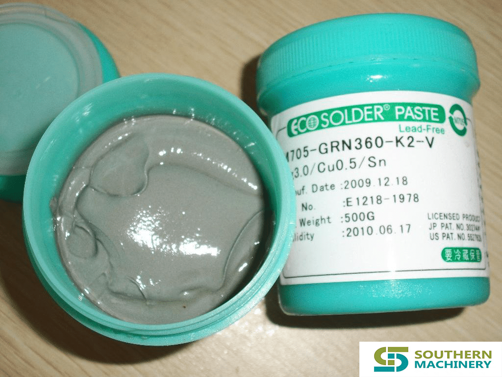

Question: Can I use a small spatula to remove misprinted solder paste from the board? Will this get the solder paste and small tin beads into the holes and small gaps?
Answer: Using a small spatula to remove the solder paste from the misprinted board may cause some problems. It is generally practicable to immerse the misprinted board in a compatible solvent, such as water with an additive, and then remove the small tin beads from the board with a soft brush. I prefer to soak and wash repeatedly instead of violent dry brush or shovel. After the solder paste is printed, the longer the operator waits to clean the misprint, the harder it is to remove the solder paste. Misprinted boards should be placed in the soaking solvent immediately after the problem is discovered, as the solder paste is easily removed before it is dried.
Avoid wiping with a strip of cloth to prevent solder paste and other contaminants from smearing on the surface of the board. After soaking, brushing with a gentle spray can often help remove unwanted tins. It is also recommended to dry with hot air. If a horizontal stencil cleaner is used, the side to be cleaned should face down to allow the solder paste to fall off the board.
As usual, note that some details can eliminate undesirable conditions, such as misprinting of the solder paste and removal of the solder paste from the board. It is our goal to deposit the right amount of solder paste at the desired location. Stained tools, dry solder paste, and misalignment of the stencils and plates can cause undesirable solder paste on the underside of the stencil or even the assembly. During the printing process, the template is wiped with a certain pattern between printing cycles. Ensure that the template is seated on the pad, not on the solder mask, to ensure a clean solder paste printing process. On-line, real-time solder paste inspection and inspection prior to reflow after component placement are process steps that reduce process defects prior to soldering.
For fine-pitch stencils, if damage is caused between pins due to thin stencil cross-section bending, it can cause solder paste to deposit between the pins, causing printing defects and/or short circuits. Low viscosity solder paste can also cause printing defects. For example, high operating temperatures or high blade speeds can reduce the stickiness of the solder paste during use, resulting in printing defects and bridging due to excessive solder paste deposition.
In general, the lack of adequate control of materials, solder paste deposition methods and equipment are the main causes of defects in the reflow soldering process.
Question: What type of assembly board depaneling equipment provides the best results?
Answer: There are several sub-board systems that offer a variety of techniques for slab assembly boards. As a rule, there are many factors that should be considered when selecting such a device. Regardless of whether there is routing, sawing or blanking to separate individual panels from the composite panel, stable support during the splitting process is the most important factor. Without support, the resulting stress can damage the substrate and solder joints. Distorting the plate, or stressing the assembly during the splitting, can result in hidden or significant defects. While sawing often provides minimal clearance, shearing or die cutting with tools can provide cleaner, more controlled results.
In order to avoid component damage, many assemblers attempt to maintain component solder joints at least 5.08 mm from the edge of the board when the splitter is required. Sensitive ceramic capacitors or diodes may require extra care and consideration.
1,Please visit : www.smthelp.net
2, Find us more: https://www.facebook.com/autoinsertion
3, Know more our team: https://www.linkedin.com/in/ming-gan118/
4, Welcome to our factory in Shenzhen China
5, See more video in Youtube: Auto+Insertion
6, Looking for more informations: ming@smthelp.net
7.Wechat/Whatsapp/skype:+86 18126316729
Related connections:
1. 3 minutes to complete a SMT stencil cleaning, improving the quality of your electronic products:S-1688 stencil-cleaning-machine
https://www.smthelp.net/product/pneumatic-stencil-cleaner-machine-s-1688

2.How to produce SMT high quality products? (for aviation, aerospace, medical products)pcba-cleaning-machine:
https://www.smthelp.net/product/pcba-cleaning-machine


0201 assembly, from difficult to conventional placement
This article explains and discusses the guiding principles governing 0201 placement in both high-volume and high-mix assembly operations.
By Ming Gan, ming@smthelp.net
Although generally considered to be a relatively recent development, printed circuit boards (PCBs) have been available since the early 1950s. Since then, the demand for smaller, lighter, and faster electronic products has driven electronic components, PCB, and assembly equipment technology toward SMT.
The earliest general acceptance of SMT occurred in the early 1980s, when machines such as the Dynapert MPS-500 and FUJI CP-2 entered the market. At that time, 1206 (3216) resistors and capacitors were the most popular placement components. However, in one or two years, 1206 gave way to 0805 (2125) as the most common component package for SMT placement.
During this time, both machines and components evolved rapidly. As the machine became faster and more flexible, the 0603 (1608) component began to evolve. At this point, many assembly machine manufacturers went back to the R&D, research and development lab to re-evaluate the technology used to accommodate these newer, smaller components. Higher resolution cameras and smaller vacuum nozzles are among the variations that these components bring to the assembly equipment.
The emergence of 0402 (1608) packaging poses further challenges in all aspects of PCB assembly. In terms of machine development, vacuum nozzles have become smaller and more fragile. A new focus is placed on the component’s feeder, which acts as a unit for improvement, giving the machine more accurate parts.
With the advent of 0402 components, process challenges have increased to those that need to be addressed for successful component placement. Solder paste printing becomes even more critical – stencil thickness and solder paste mesh are increasingly important process considerations. The technology required for such placement also involves significant new costs.
The combination of these factors creates a new form of packaging that is the slowest to adopt in the history of the electronics industry. In total, for almost five years, 0402 packaging was widely accepted in the industry – and many assembly plants today never put a 0402 sheet.
Now, I entered 0201.
Over the past year and a half, 0201 placement has been a key topic of discussion throughout the industry. Due to the size, weight and power consumption requirements, many OEM board assemblers need to incorporate even smaller components and technologies into their products. Contract manufacturers (CM, contract manufacturer) must also have new technologies to keep the assembly process up to date and provide customers with a complete range of services. For machine builders, the challenge is to develop more resistant to obsolete assembly equipment in an era of dynamic technological change.
0201 placement challenge
The placement of the 0201 component is more challenging than the component intervention in front of it. The main reason is that the 0201 package is approximately one-third of the corresponding 0402 size.
The previously acceptable machine placement accuracy immediately became a limitation of the introduction of 0201. In addition, the traditional industrial tapeding specification allows for too much movement for reliable 0201 placement, and the level of process control must be increased to make the 0201 placement a production reality.
Although these obstacles are very large, they are far from insurmountable. Of course, they need all the determination, because the technology necessary for the 0201 placement requires a lot of money and top management’s promise of research and development (R&D).
The key to reliable 0201 placement
At FUJI, the aggressive R&D program has produced the ability to make all circuit assembly machines compatible with 0201 at 100% speed, with a minimum suction reliability of 99.90%, a target suction reliability of 99.95%, and minimal placement reliability. It is 99.99%. In the beginning, every aspect of the design was evaluated for its ability to work on a complete 0201 program, and the combination of single elements of closely related machine component parameters proved critical to success. These parameters include:
Figure 1 Component feeder table. The R&D program concluded that the ability to precisely position the carriage table – and make minimal adjustments to compensate for the inaccuracy of the tape – is a key factor in achieving component pickup reliability above 99.95%.
To achieve this, the feeder table must be precision machined to ensure repeatable positioning of the individual feeders and combined with a high-resolution semi-closed-cycle servo system using a two-track linear moving guide. This design allows for minor adjustments – based on the results of the suction accuracy as judged by the vision system. This ensures that the component is as close as possible to the center.
Component feeder. The feeder must be manufactured to extremely tight tolerances to ensure repeatability of the suction position, regardless of component height and a large number of possible component positions. The mechanism used to position and lock the feeder in position must be durable and precise, yet be user friendly. In addition, the materials used to make the feeder must be high in strength and light in weight to allow for ergonomic operation while ensuring precise, repeatable delivery of the carrier tape.
The feeder drives the sprocket. The drive sprocket plays a key role in the ability of the machine to position the component tape. The shape, taper and length of the drive sprocket teeth significantly affect the ability of the feeder to position the tape. Other factors have also been investigated, such as the diameter of the drive sprocket and the number of belts in contact with the sprocket. Changes to the basic sprocket design resulted in improved positioning accuracy, with earlier designs increasing by 20% in the X direction and 50% in the Y direction.
Figure 2 sucks the head. After properly feeding the component, the next step is to draw the component onto the vacuum nozzle and bring it to the board. Vacuum nozzles are compliant to absorb shock during pick-and-place components, compensate for small variations in solder paste height, and reduce the risk of component breakage. For these reasons, the nozzle must be able to move within its fixture.


Material selection, material hardness, machining tolerances, and thermal characteristics must all be understood to construct a reliable suction head. The nozzle must move freely within its holder without sacrificing accuracy (Figure 1).
The nozzle shaft is assembled. The nozzle shaft is also a key design element – eliminating overdrive by keeping the entire nozzle in direct alignment with the shaft assembly. Overpressure is caused by the inertia generated when the head is moved up and down. If the nozzle and the shaft are not in a straight line, there is a little whip – or overpressure. Overpressure causes a change in positioning accuracy, which is determined by the speed of movement, the weight of the nozzle, and the weight of the component. By eliminating overpressure, direct alignment reduces the number of negative factors associated with component pick-and-place placement (Figure 2).
Figure 3 nozzle design. Variations in the design of the nozzle are an important factor in allowing the 0201 component to be received. In order to draw a 0.6×0.3 mm component, the nozzle must have an outer diameter of no more than 0.40 mm. This forms a long, thin nozzle shaft that is fragile but must also maintain precision to maintain high reliability of suction. Changes from the linear axis to the tapered design increase the nozzle strength and allow the nozzle to resist bending (Figure 3).
Matrix structure. All machines generate vibrations during operation. The base frame design is a key first step in reducing the speed and motion effects of vibration and harmonic resonance. By using a cast iron base frame and state-of-the-art structural technology, vibration and harmonic resonance can be reduced to a controllable level within the machine, so that negative effects can be dealt with.
Up to standard
Through all six key factors, the obstacles to reliable 0201 placement have been eliminated. As a result, R&D’s focus has shifted to newer, smaller components, and 0201 is no longer considered a leading edge component packaging technology.
For 0201 component placement, the accepted process window is approximately 75 μm X and 75 μm Y at 3 。. To achieve 6 贴 placement reliability, the X and Y tolerances must be reduced to 50 μm. The latest high-speed placement equipment has a rating of 66μm with an actual standard deviation of approximately 35~45μm. As the 0201 component becomes more widely used and the manufacturing process becomes tighter, improved accuracy can be achieved.
The difference in component size between suppliers poses a challenge to 0201 feeding and placement. Bulk feeding is being opened and should be available in 2001.
Although the machine now has this capability, only a small percentage of users will be ready to take the 0201 placement in the next 12 to 24 months. This is similar to the introduction of a ball grid array (BGA) and 0402 components, in which the machine’s capabilities are ahead of the process state.
Challenge ahead
While the placement of 0201 components is now a standard feature of new placement equipment, additional work is needed to improve the overall process for the end user. The relationship between machine builders, component suppliers, board manufacturers, formwork factories, and solder paste manufacturers needs to be strengthened to create a more seamless development process. The end result will be a unified understanding of the process and a better working relationship that will benefit end users, especially by making new production technologies faster and more efficient.
By Ming Gan, ming@smthelp.net

Bulk material handle method and process on SMT production line
SMT patch bulk material problems have plagued many SMT people, as we all know, once the placement machine starts, there will definitely be a problem in the SMT production line. For a variety of reasons, many bulk materials are produced, thrown, or are originally bulk materials, or other reasons. Some bulk materials, such as resistors, capacitors, inductors, etc., are not easily distinguishable and have little value in themselves, and there is no value for reuse. However, for large devices, especially some imported chip components, they are of high value and can be distinguished and distinguished, so they are generally reused. However, for scattered components, if the original package is a tray or a suitable tray, the problem may be solved better. Otherwise, it may be more difficult to handle. Southern Machinery today will talk about the handling of bulk material in the SMT production line. Method and process.
First, the bulk material handle process

Collecting materials – material personnel sorting materials – using electrostatic bags to pack – paste material specifications – technicians based on bulk material springboard – hand paste bulk material – QC confirmation
Second, the definition
Bulk material: refers to the components that are separated from the original packaging during the production process due to machine throwing, or loading and unloading materials.
Third, job responsibilities
Material staff: responsible for the collection, classification, identification, storage, placement, and placement information of bulk materials, and the material loss rate is calculated according to the order.
QC in front of the furnace: responsible for the manual placement of bulk materials, the front back grain and material code confirmation, PCBA mark, and the classification of bulk materials.
Technician: Responsible for programming, patch production, monitoring patch quality distribution and timely improvement.
QC after the furnace: It is responsible for checking and checking the first piece of all the machines, and the quality is abnormal. Immediate feedback is provided to the front station to improve and track.
Fourth, the work content


Use of PCB Pallets in Wave Soldering
Patch components are used more and more on the circuit board, but there are still some perforated components between them. For this kind of board, selective soldering is the best solution, but not every company has enough funds to purchase selective soldering equipment, or the number of this type of circuit board is too small, specifically to buy selective soldering equipment is not Cost-effective. Manual welding is prohibited in certain industries such as the automotive industry

Therefore, in PCB wave soldering, using trays to block those patch components is a good method: reliable, fast production, and adaptability to high-capacity requirements.
www.smthelp.com

The benefits of using trays:
Lead-free soldering requires higher soldering temperatures. Therefore, the circuit board is more easily bent during welding. The tray provides maximum protection of the circuit board during soldering and prevents bending.
Similarly, in the automotive and consumer electronics industries, many special-shaped circuit boards have emerged for the needs of applications. It is sometimes difficult to transport these shaped plates with conventional chain rails and mesh belts, and placing the circuit board plates in trays allows any type of circuit board to be shipped.

By soldering some of the bottom components through the tray, it is also possible to use PCB wave soldering equipment for selective soldering of the product.
Since most trays are thick (sometimes 15 mm), solder certainly does not flow to the top of the board. The oxide layer on the solder surface will also be washed away by the edge of the tray before the board reaches the peak, so that when the solder starts, the tin is relatively clean.
By adding some stiffening strips to the tray, it can increase its hardness to withstand high-strength welding. It is also possible to install heat-absorbing blocks, component fixing devices and some other auxiliary devices on the upper part.
The use of pallets also helps standardize the width of the product line, soldering different circuit boards on the same production line, and can use bar code readers and other identification tools to quickly change process programs for different boards.
Although there are many advantages to using trays in lead-free soldering, it can also cause solder balls.
Requirements for pallet materials:
In order to maximize the service life of the trays, the trays must be made of materials that can withstand high temperatures and harsh process conditions, especially for lead-free soldering.
www.smthelp.com

To meet these requirements, the material used to make the tray must meet the following characteristics:
• High dimensional stability
• Good thermal shock resistance
• Can remain flat after repeated use
• Corrosion resistance (flux and cleaning agent)
• Does not absorb moisture
The use of the tray brings the process problems:
The flux system must be able to spray the circuit board completely with flux. Poor tray designs can lead to “shadow effects” in flux spraying: Some parts of the board have insufficient flux or no flux at all. The flux must be sprayed onto the board and spread through the capillary action.
Before the tray touches the crest, it must be heated in the preheating unit. A typical preheating configuration is a combination of heat pipes and hot air forced convection. If the temperature drops before contact with the peak, the tray will have an endothermic effect, making the welding process difficult to control.
The use of trays requires a wave height of up to 0.5 inches (12.5 mm). In the case of such a high pump speed, the use of nitrogen can help reduce dross. When using pallets in lead-free soldering, Vitronics Soltec’s perturbed “smart wave” can also promote tinning of the perforated component.
In addition, we must pay special attention to keeping the circuit board in the pallet flat. If there is a gap between the circuit board and the tray, the flux will flow into the gap, and the solder will flow to the board when passing through the peak. This will cause solder residue on the board.

The gap between the circuit board and the tray may cause solder residue on the circuit board
Circuit board and tray design recommendations:
Avoid placing larger components near the piercing element as this can cause shadowing effects and tin difficulties.
Leave proper clearance around the pins and edges of the through-hole components so that solder can flow. These tin guides will guide the solder to the seat of the tray opening, while also greatly improving the solder flowability.
www.smthelp.com

The tin slot at the tail of the tray allows the solder to flow smoothly back to the tin tank
The opening of the tray should be as large as possible to facilitate the flow of solder. This will reduce some of the welding defects, such as: short circuit and solder balls. At the same time, it is also beneficial to the solder filling of the through hole, because the large opening also means that there is more energy to enter the welding area.
Prepared by :ming@smthelp.com

Features:
1, using the next vacuum mode, in line with the theory of free fall, good dust collection effect.
2, special jig fixed more solid, to avoid the poor positioning caused by the cutting accuracy error.
3, the system automatically fixes according to the product installation location, to ensure high-precision product cutting requirements.
4, the static eliminator is installed in addition to electricity, dust blower continued to work to eliminate static electricity generated when cutting high-speed spindle to avoid damage caused by static electricity parts to avoid accumulation of dust due to static electricity.
5, the use of safety doors, reduce noise and dust, improve safety.
Vacuum cleaner with vacuum collection box (according to production capacity or cutting dust collection time scheduled maintenance)
。
| PCB Separator also called PWB Depaneling machine. Rotate router bit to cut high-density component PCB panel to single products v-groove or perforated line. Utilize all of our accumulated technology to help minimize dust attach on PCB. Router machine has following features. |
|
|
|
|
|
|

| Function Items |
功能项 |
参数/Hardware Demand |
| Model |
型号 |
ASC-2500S |
| Dimension |
机台结构 |
L650*W650*H1765mm |
| Power |
电源 |
220V/50HZ |
| Machine Wattage |
机台功率 |
3.6KW |
| Weight |
重量 |
About 300KG |
| Cleaner Dimension |
吸尘器尺寸 |
内置式(Inside)/L500*W490*H590mm |
| Cleaner Wattage |
吸尘器功率 |
2.2KW/220V |
| Table Dimension |
工作台尺寸 |
260mm*260mm |
| Cutting Speed |
X、Y轴切割速度 |
0-100mm/s |
| X,Y,Z axis Driving Speed | X、Y、Z轴驱动速度 | X、Y轴0-1000mm/s(min),Z轴0-750mm/s(min),伺服马达方式驱动X, Y axis 0-1000mm/s (min), Z axis 0-750mm/s (min), servo motor drive |
| Repeatability Accuracy | 机台重复精度 | ±0.01mm |
| Working Area | 工作区域(可加工行程) | X:0-260mm,Y:0-260mm,Z:0-80mm |
| PCB Thickness | 切割PCB厚度范围 | 0.5-5mm |
| Router Bit Diameter | 铣刀直径 | 0.8-3.0mm |
| Cutting Precision | 切割精度 | ±0.01mm |
| Cutting Ability | 切割能力 | 具有切割直线、圆弧、圆、L型和U型的能力 |
Linear, Circular, U-curve, Arc, L-curveCutter Change刀具更换系统可手动换刀系统,需工具(随机配送)
Manual, tools needed Cutter Attrition System刀具磨损系统可智能设定铣刀下刀段数(0-5段)
The number of milling cutters (0-5 section)Break Detection断刀检测无(none)Cutter Life Control刀具寿命控制程序控制(controlled by Program)Table NumberTable数量1个Spindle Speed主轴转速60000rpmSpindle Cooling System主轴冷却系统气冷方式Air cooling modeCleaner Mode集尘方式下集尘(collect dust downside)Working Power工作电源220V ,50HZAir press空压供给0.4MpaSafety Device安全装置采用安全防护门加门锁感应器Safety door and door lock sensorMode机型模式离线机型,手工装载卸载PCBA(offline, load and unload PCBA by hand)Auto failure test and repair mode故障自动检知维修模式系统具有自我诊断功能,实时错误信息显示,能直观地查询设备各个IO端口状态,易于排除故障。
Self-diagnosis,display failure information in real time, query IO state visually, easy for troubleshootingComputer & Operation system电脑和操作系统工控机、Windows 7
IPC, Windows 7Program Backup程式备份USBSoftware access control软件权限管理密码保护,依权限进入对应操作界面,保护系统重要参数。(Password protection,the operator enter corresponding interface according to authority to protect important parameters.)Programming编程可视化界面,单个程序切割点容量无限制,切割路径动态模拟。(Visual interface, the cutting point capacity for a single program should be over 400, dynamic simulation of cutting schedule.)Auto correction of the mark pointMark点自动校准功能具备Mark点自动校准功能(Yes)Fixture 治具万用治具可供选择(universal fixture)Voice control噪音控制运行时,噪声小于60分贝(离设备一米距离测量)
≦78 dB(measured in 1M’s distance )Maintenance Period保修周期整机1年或以上,主轴2年或主轴3000小时保养服务。
1 years or more, spindle for 2 years or spindle maintenance service for 3000 hours.Technology Support技术支持及培训提供设备操作、编程,硬件保养,维修培训服务;程序永久免费升级。(Offer service of operation, programming, hardware caring and maintenance training; free upgrade of application. )
| 主轴Main axis | S4225-B60 S4225-B60 |
| CCD | IMAGING |
| 丝杆Ball Screw | Hiwin进口精密研磨滚珠丝杠Hiwin precise grinding ball screw imported |
| 导轨Lead Rail | Hiwin进口直线加宽导轨Hiwin straight widened lead rail imported |
| 伺服电机Servo Motor | 松下Panasonic |
| 静电消除器Static Eliminator | ADK-801ADK-801 |
| 工控主机IPC Host | 研华ADHNTECH |
| 运动控制卡Motion control card | 固高ADTECH |
| 显示器Monitor | 华硕ASUSASUS |
| 控制系统Control System | Windows7 |
| 操作界面Operation Inteface | Windows7 |
| 编程Program | 在线方式Online |
| 视觉系统Visual System | ASC视觉分板机系统像素计算型高精度CCD视觉定位校正系统CCD Visual alignment system |
| 设备尺寸Machine size | L1380*W1250*H1875mmL1380*W1250*H1875mm |
| 重量Weight | 约300KG |
| 底脚可调高度Foot Height adjustable | 50~70mm |
| 板最大厚度Max.PCB Thickness | 5mm |
| 整机功率(含集尘器)Power (included dust collector) | 4000w |
| 最大转速Max Rotation Speed | 60000rpm/min |
| 冷却方式Cool Down | 气冷+夹具散热cold air and clamp radiating |
| 更换工具方式Tool replacement | 专用扳手更换by specialized tool |
| 最大切割速度Shear speed | 0~100mm/s |
| 最大移动速度Max Moving Speed | 1000mm/s |
| 切割重复精度Shear Repeat Accuracy | ±0.02mm |
| 集尘器功率Dust Collector Power | 2.2kw 220v三相电机2.2kw 220v three phase motor |
| 气压Pressure | 0.4Mpa以上0.4Mpa above |
| 编程方式Program mode | 在线编程Online program |
| 编辑功能Edit | 直线、孔状、圆弧、圆Straight line, hole, arc, circuit |
| 程序存储Procedure Storage | 根据需要选择存储位置choose storage position according to needs |
| 配置编程Camera | IMAGING高像素彩色CCD IMAGING high pixel color CCD |
| 刀具直径补偿Compensation on Blade DIA | 多种补偿方式供用户选择many choices for option |
| 三色灯Three Color Indicator | LED三角灯监视机器的各种工作状态LED LED indicator monitoring working status of the machine |
| 刀具好坏检测Blade Inspection | 刀具寿命根据用户设定的下沉段数、产品数量及切割长度等方式选择According to PCB quantity and shear length |
| 马达过热检测Motor overheat Inspection | 有过载、过热、低电压等保护功能Protection on overload, overheat, low voltage,etc |
| 伺服过载检测Servo overload Inspection | 有过载、低电压、线路是否正常等保护功能Protection on overload, low voltage, circuit, etc |
| 主轴寿命跟踪Main axis life Tracking | 主轴寿命自动检测Automatic Inspection on Life of main axis |
| 分板计数Shear Qty Counting | 分板计数、计时Counter on shear quantity and Time recording |
| 机器报错记录Error Record | 软件自动记忆机器所有报警记录automatic memory on all error |
| 轴位置精度Axis Position Accuracy | 0.001mm |
| 分板精度Accuracy of Shear | ±0.01mm |
| 工作范围保护罩Safety Shell of working range | 采用四面门窗保护方式Using four door and window protection |
| 门的互锁保护传感器Protection Inductor on Interlocking | 安全门微动开关感应able to induct inches switch of safety door |
| 紧急停止按钮Emergency Stop Button | 有 Yes |
| 铣刀方式Milling | 采用左旋铣刀,直径0.8-3.0MM范围可选Milling by left rotation, DIA of 0.8-3.0mm optional |
| 加工方式Process | 模拟运行和实际加工,单Table可以交替加工不同PCBA板Simulation and actual operation, a single Table can be alternately processed different PCBA board |

Features:
1, vacuum cleaner built-in vacuum mode, in line with the theory of free fall, dust collection effect is good.
2, the equipment adopts automatic loading and unloading products, can be directly on the wiring body or on the board machine.
3, using a special fixture with products (pcb), to avoid poor placement caused by cutting error.
4, the system automatically fixes the installation error, to ensure product precision cutting requirements.
5.It is equipped with static eliminator. When dividing, the dust remover will work continuously to eliminate the static electricity generated when the high-speed spindle cut. It can avoid the damage caused by the static electricity and avoid the accumulation of dust due to static electricity.
6, the use of safety doors, reduce noise and dust, improve safety.
7, there are follow-up vacuuming function, dust collector attached to the dust collection box (according to capacity cutting needs or dust collection time scheduled maintenance).
8, touch the display as a display, setting, control, can display more content, the operation directly through the touch screen operation, easy to operate.
9, can be directly docking the next equipment, sub-plate processing.
10, in the cutting process, if broken knife, equipment with automatic tool change function, without manual to change the knife.
11, Equipment using Mes system, the factory can control the machine everywhere, equipped with WIFI function can be controlled.

| Function Items |
功能项 |
Hardware Demand |
| Model |
型号 |
ASC-3500S(加皮带) |
| Dimension |
机台结构 |
(含皮带)L1750*W1100*H1850mm |
(不含皮带)L1450W1100H1850mmPower
电源
220V/50HZMachine Wattage
机台功率
5.5KWWeight
重量
About1000KGCleaner Dimension
吸尘器尺寸
内置式(Inside)/L450W450H450mmCleaner Wattage
吸尘器功率
2.2KWTable Dimension
工作台尺寸
350mm*350mmCutting Speed
X、Y轴切割速度
0-100mm/sX,Y,Z axis Driving SpeedX、Y、Z轴驱动速度X、Y轴至少1000mm/s(min),Z轴至少750mm/s(min),伺服马达方式驱动(driven by servo motor)Repeatability Accuracy机台重复精度±0.02mmMechanical hand X, Z stroke机械手X、Z行程X:420mm、I:60mmManipulator X, Z running speed机械手X、Z运行速度200mm/sMechanical hand grasp mode机械手抓取方式真空吸附Precision of repeated positioning of manipulator机械手重复定位精度±0.04mmMechanical hand grab products (PCB) dimensions机械手抓取产品(PCB)尺寸350mm*350mmPCB feeding trackPCB上料轨道皮带输送;宽度60~360mm可调Split plate product分板产品下料皮带输送;宽度420mmWorking Area工作区域(可加工行程)X:300mm,Y:350mm,Z:0-50mmPCB Thickness切割PCB厚度范围0.5-2mm(or thicker),或范围更大 Router Bit Diameter铣刀直径0.8-2.0mmCutting Precision切割精度±0.01mmCutting Ability切割能力具有切割直线、圆弧、圆、L型和U型的能力
Linear, Circular, U-curve, Arc, L-curveCutter Change刀具更换系统自动换刀系统 Automatic tool changing systemCutter Attrition System刀具磨损系统可智能设定铣刀下刀段数(5段)
Smart to set the no. of knife section(0-3)Break Detection断刀检测有(have)Cutter Life Control刀具寿命控制程序控制(controlled by Program)Product testing产品检测有(have)Table NumberTable数量1个Table FunctionTable功能并行Table运行方式;设备能实现1个Table联动功能(1 tables run in parallel)Spindle Speed主轴转速60000rpmSpindle Cooling System主轴冷却系统风冷方式(air cooling)Cleaner Mode集尘方式下集尘(collect dust downside)Working Power工作电源220V ,50HZAir press空压供给0.5Mpa以上(above)Safety Device安全装置采用安全防护门或感应器(security door or sensor)Mode机型模式在线机型,全自动装载卸载PCBA(offline, load and unload PCBA by hand)Auto failure test and repair mode故障自动检知维修模式系统具有自我诊断功能,实时错误信息显示,能直观地查询设备各个IO端口状态,易于排除故障。
Self-diagnosis,display failure information in real time, query IO state visually, easy for troubleshootingComputer & Operation system电脑和操作系统工控机、Windows 7或以上版本。
PIC、Windows 7 or more advanced versionProgram Backup程式备份USBSoftware access control软件权限管理密码保护,依权限进入对应操作界面,保护系统重要参数。(Password protection,the operator enter corresponding interface according to authority to protect important parameters.)Programming编程可视化界面,单个程序切割点容量无限制,切割路径动态模拟。(Visual interface, the cutting point capacity for a single program should be over 400, dynamic simulation of cutting schedule.)Auto correction of the mark pointMark点自动校准功能具备Mark点自动校准功能(Yes)Fixture 治具ASC-3500S专用治具ASC-3500S special fixtureVoice control噪音控制运行时,噪声小于60分贝(离设备一米距离测量)
≦78 dB(measured in 1M’s distance )Maintenance Period保修周期整机1年或以上,主轴建议2年以上并在保内提供主轴3000小时保养服务。
Over 1 year for the whole machine, and over 2 years for the spindle, and the spindle enjoys 3000 hours’ maintenance during the periodTechnology Support技术支持及培训提供设备操作、编程,硬件保养,维修培训服务;程序永久免费升级。(Offer service of operation, programming, hardware caring and maintenance training; free upgrade of application. )


