Cut and Clinch Footprints
The cut and clinch cuts the component leads after they are inserted
through the PC board and then clinches them against the underside
of the PC board, securing the component in place.



Cut and Clinch Footprints
The cut and clinch cuts the component leads after they are inserted
through the PC board and then clinches them against the underside
of the PC board, securing the component in place.


Simplifies receiving, storage and retrieval
Delivers full traceability
Automatically monitors stock levels
The SMT intelligent electronic material rack is a high floor area ratio shelf used to store the SMT patch devices.When loading, the materials are placed in the corresponding card position according to the plate, bind the LED indicator on the shelf through the corresponding relationship of the QR code of the material number / card position, and the ERP / MES system of the docking enterprise will automatically realize the operation of sending and receiving materials according to the light indication.
Delivery time is saved from two hours to 15 minutes, efficiency increase 8 times
Each shelf can store 1,400 plates of materials disorderly, and save the inventory area by 40%
The location of each item is quickly checked, and the inventory time can be reduced from 2 days to 2 hours
Material / warehouse / work order / station automatic binding, feeding and feeding process can prevent rigidity and error
Keyword guide: circuit board cleaning, circuit board cleaning, PCBA circuit board cleaning, PCBA circuit board cleaning, solvent cleaning agent, water-based cleaning agent, water-based cleaning technology
Before discussing the question of “why use water-based cleaners for PCBA circuit board cleaning”, let’s take a look at the advantages and disadvantages of solvent-based cleaners.

Organic solvent cleaning agents can be divided into flammable cleaning agents and non-flammable cleaning agents according to their safety performance. The former are mainly organic hydrocarbons, alcohols and esters, and the latter are mainly chlorinated hydrocarbons and fluorinated hydrocarbons. Its process characteristics are introduced as follows:
If we take advantage of the advantages and disadvantages of organic solvent cleaning and avoid the disadvantages, wouldn’t it be perfect? Is it feasible? The answer is yes! Water-based cleaners were born around solving this problem.
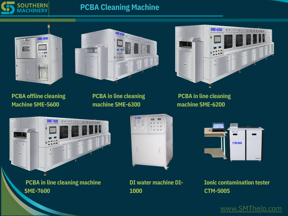
Water-based cleaning technology is made of water as the cleaning medium, and various additives such as surfactants, solvents, defoaming agents, and corrosion inhibitors are added, and various pollutants are removed through various mechanisms such as dissolution, adsorption, and infiltration.
The main features of the water cleaning process are non-flammable and explosive, non-toxic and environmentally friendly, safe in operation, strong in cleaning ability, low in loss during cleaning, and low in cost. Because of the large degree of freedom of active ingredients, the formula can be formulated according to the special requirements of PCBA, which solves many problems. The problems that cannot be solved by organic solvent cleaning agents have a wide cleaning range and strong applicability. The flexible components of water-based cleaning agents can greatly meet the needs of customers, especially when ultrasonic cleaning and spray cleaning are used, they are more advantageous than organic solvents. .
Of course, water-based cleaning agents also have shortcomings, such as high requirements for cleaning equipment, and the need to treat invalid cleaning agents, that is, waste water.
Combining the characteristics of solvent-based cleaning agents and water-based cleaning agents, it is not difficult to find that with the strengthening of safety and environmental protection awareness and the increase of special cleaning needs for PCBA, water-based cleaning agents stand out because of their flexible formulas and components, representing the future of PCBA cleaning. Technology development direction.
We understand that SMT machine training and after sales service are a key to choose a new supplier.
Please click below links to see machine 3D models:
https://www.smthelp.net/html/SMT Production line.html https://www.smthelp.net/html/THT_Auto_Insertion_full_line.html
SMT AI Peripheral Equipments and Spare parts
| Item | Product Name | URL |
| 1 | Bicycle | https://www.smthelp.net/html/Bicycle.html |
| 2 | FUJI_NXT_8mmfeeder | https://www.smthelp.net/html/FUJI_NXT_8mmfeeder.html |
| 3 | IC_tube_to_reeltapepackingmachine | https://www.smthelp.net/html/IC_tube_to_reeltapepackingmachine.html |
| 4 | PCBA_THT_fixture | https://www.smthelp.net/html/PCBA_THT_fixture.html |
| 5 | RS-1_Vibration_tube_FEEDER_BANK | https://www.smthelp.net/html/RS-1_Vibration_tube_FEEDER_BANK.html |
| 6 | SMT Label feeder.htm | https://www.smthelp.net/html/SMT Label feeder.htm |
| 7 | SMT reel tape feeder 72mm width | https://www.smthelp.net/html/SMT reel tape feeder 72mm width.html |
| 8 | SMT_axial_Radial_feeder_bank | https://www.smthelp.net/html/SMT_axial_Radial_feeder_bank.html |
| 9 | SMT_label_mounter | https://www.smthelp.net/html/SMT_label_mounter.html |
| 10 | SMT_Odd_Bowl_feeder | https://www.smthelp.net/html/SMT_Odd_Bowl_feeder.html |
| 11 | SMT_tray_feeder_B | https://www.smthelp.net/html/SMT_tray_feeder_B.html |
| 12 | SMThelp_PCBA-smt | https://www.smthelp.net/html/SMThelp_PCBA-smt.html |
| 13 | UIC_autoinsertion_Spareparts_list | https://www.smthelp.net/html/UIC_autoinsertion_Spareparts_list.html |
| 14 | wave_soldering_line | https://www.smthelp.net/html/wave_soldering_line.html |
| 15 | Wave soldering machine | https://www.smthelp.net/html/Wave soldering machine.html |
| 16 | Adapter JUKI Nozzle with Nozzle | https://www.smthelp.net/html/Adapter JUKI Nozzle with Nozzle.html |
| 17 | Auto Insertion Axial Radial Oddform Production line | https://www.smthelp.net/html/Auto Insertion Axial Radial Oddform Production line.html |
| 18 | Bowl Radial reel feeder w JUKI cart | https://www.smthelp.net/html/Bowl Radial reel feeder w JUKI cart.html |
| 19 | Conveyor 1M nolight | https://www.smthelp.net/html/Conveyor 1M nolight.html |
| 20 | Feeder cart-Bowl Axial Radial Tube | https://www.smthelp.net/html/Feeder cart-Bowl Axial Radial Tube.html |
| 21 | FUJI glue nozzle | https://www.smthelp.net/html/FUJI glue nozzle.html |
| 22 | FUJI nozzle WGW-CZ | https://www.smthelp.net/html/FUJI nozzle WGW-CZ.html |
| 23 | FUJI nozzle WJH-CZ | https://www.smthelp.net/html/FUJI nozzle WJH-CZ.html |
| 24 | fuji NXT 8mm feeder | https://www.smthelp.net/html/fuji NXT 8mm feeder.html |
| 25 | fuji NXT 8mm feeder | https://www.smthelp.net/html/fuji NXT 8mm feeder.html |
| 26 | FUJI Sfab Radial tape feeder | https://www.smthelp.net/html/FUJI Sfab Radial tape feeder.html |
| 27 | Gripper nozzle for E-cap | https://www.smthelp.net/html/Gripper nozzle for E-cap.html |
| 28 | Hign end conveyor 1M w PCBA | https://www.smthelp.net/html/Hign end conveyor 1M w PCBA.html |
| 29 | JUKI 2 layer bowl feeder w cart | https://www.smthelp.net/html/JUKI 2 layer bowl feeder w cart.html |
| 30 | JUKI Gripper_Nozzle 2583 C | https://www.smthelp.net/html/JUKI Gripper_Nozzle 2583 C.html |
| 31 | Juki Nozzle 500 Assembly | https://www.smthelp.net/html/Juki Nozzle 500 Assembly.html |
| 32 | Juki Nozzle 500 Head Assembly | https://www.smthelp.net/html/Juki Nozzle 500 Head Assembly.html |
| 33 | JUKI Radial tape feeder big span | https://www.smthelp.net/html/JUKI Radial tape feeder big span.html |
| 34 | JUKI Radial tape L lead feeder | https://www.smthelp.net/html/JUKI Radial tape L lead feeder .html |
| 35 | Juki2050 Feeder Cart w Radial axial | https://www.smthelp.net/html/Juki2050 Feeder Cart w Radial axial.html |
| 36 | Mobile charger PCBA | https://www.smthelp.net/html/Mobile charger PCBA.html |
| 37 | Nozzle adepter | https://www.smthelp.net/html/Nozzle adepter.html |
| 38 | Nozzle base | https://www.smthelp.net/html/Nozzle base.html |
| 39 | Odd form insertion Feeders w loader-unloader | https://www.smthelp.net/html/Odd form insertion Feeders w loader-unloader.html |
| 40 | Panasonic Al Spare parts list 2 | https://www.smthelp.net/html/Panasonic Al Spare parts list 2.html |
| 41 | Panasonic CM602 Bowl feeder | https://www.smthelp.net/html/Panasonic CM602 Bowl feeder.html |
| 42 | PCB Combo loader destacker+Magazine | https://www.smthelp.net/html/PCB Combo loader destacker+Magazine.html |
| 43 | PCB Magazine | https://www.smthelp.net/html/PCB Magazine.html |
| 44 | Power supplier | https://www.smthelp.net/html/Power supplier.html |
| 45 | Radial Cutter clinch head | https://www.smthelp.net/html/Radial Cutter clinch head.html |
| 46 | Radial Insertion Head Assy w Ecap | https://www.smthelp.net/html/Radial Insertion Head Assy w Ecap.html |
| 47 | RS-1 FEEDER BANK w Vibe tube feeder | https://www.smthelp.net/html/RS-1 FEEDER BANK w Vibe tube feeder.html |
| 48 | S3010A Radial Insertion machine inline | https://www.smthelp.net/html/S3010A Radial Insertion machine inline.html |
| 49 | S3010A Radial machine no cover | https://www.smthelp.net/html/S3010A Radial machine no cover.html |
| 50 | S7000 Odd Form Insertion machine | https://www.smthelp.net/html/S7000 Odd Form Insertion machine.html |
| 51 | S7000 Oddform insertion 3 bowl feeder | https://www.smthelp.net/html/S7000 Oddform insertion 3 bowl feeder.html |
| 52 | S700D Odd Form Insertion machine | https://www.smthelp.net/html/S700D Odd Form Insertion machine.html |
| 53 | S-7020T Terminal insertion | https://www.smthelp.net/html/S-7020T Terminal insertion.html |
| 54 | S-7040 Oddform insertion w 4 bowl feeder | https://www.smthelp.net/html/S-7040 Oddform insertion w 4 bowl feeder.html |
| 55 | S-7040T Oddform insertion w Tray feeder | https://www.smthelp.net/html/S-7040T Oddform insertion w Tray feeder.html |
| 56 | SBH250 NGOK dual nagazine PCB unloader w magazine | https://www.smthelp.net/html/SBH250 NGOK dual nagazine PCB unloader w magazine.html |
| 57 | SBU460 Bare PCB destacker loader +conveyor | https://www.smthelp.net/html/SBU460 Bare PCB destacker loader +conveyor.html |
| 58 | SLD250 PCB loader w magazine | https://www.smthelp.net/html/SLD250 PCB loader w magazine.html |
| 59 | SLD250 S4020A+S3010A SULD250 Al machine production line | https://www.smthelp.net/html/SLD250 S4020A+S3010A SULD250 Al machine production line.html |
| 60 | SLD250+ S3020A +SULD250 Radial Insertion machine inline | https://www.smthelp.net/html/SLD250+ S3020A +SULD250 Radial Insertion machine inline.html |
| 61 | SLD250+S3010A(s)+SULD250 Al machine production line | https://www.smthelp.net/html/SLD250+S3010A(s)+SULD250 Al machine production line.html |
| 62 | SLD250+S3010A+S7040T(tray feeder)+SULD250 Al machine production line | https://www.smthelp.net/html/SLD250+S3010A+S7040T(tray feeder)+SULD250 Al machine production line.html |
| 63 | SLD390 SMT PCB loader (L-R) | https://www.smthelp.net/html/SLD390 SMT PCB loader (L-R).html |
| 64 | SLD390L SMT PCB loader(L-R) | https://www.smthelp.net/html/SLD390L SMT PCB loader(L-R).html |
| 65 | SLD390L SMT PCB loader(L-R)w magazine | https://www.smthelp.net/html/SLD390L SMT PCB loader(L-R)w magazine.html |
| 66 | SLVC200 Vacuum PCB loader +conveyor | https://www.smthelp.net/html/SLVC200 Vacuum PCB loader +conveyor.html |
| 67 | SLVC200 Vacuum PCB loader | https://www.smthelp.net/html/SLVC200 Vacuum PCB loader.html |
| 68 | SMT 2 rail bowl feeder | https://www.smthelp.net/html/SMT 2 rail bowl feeder.html |
| 69 | SMT BHS line1 | https://www.smthelp.net/html/SMT BHS line1.html |
| 70 | SMT CART FEEDER | https://www.smthelp.net/html/SMT CART FEEDER.html |
| 71 | SMT customized nozzle design n manufacturing | https://www.smthelp.net/html/SMT customized nozzle design n manufacturing.html |
| 72 | SMT Drone main control board | https://www.smthelp.net/html/SMT Drone main control board.html |
| 73 | SMT Gripper nozzle customized | https://www.smthelp.net/html/SMT Gripper nozzle customized.html |
| 74 | SMT Gripper nozzle JUKI | https://www.smthelp.net/html/SMT Gripper nozzle JUKI.html |
| 75 | SMT label feeder | https://www.smthelp.net/html/SMT label feeder.html |
| 76 | SMT nozzle list 1 | https://www.smthelp.net/html/SMT nozzle list 1.html |
| 77 | SMT Nozzle MiniChuck_closing w component | https://www.smthelp.net/html/SMT Nozzle MiniChuck_closing w component.html |
| 78 | SMT PCB 90 turn conveyor | https://www.smthelp.net/html/SMT PCB 90 turn conveyor.html |
| 79 | SMT PCB conveyor 1M w lighting | https://www.smthelp.net/html/SMT PCB conveyor 1M w lighting.html |
| 80 | SMT PCB Flipper (turn over) + conveyor w PCBA | https://www.smthelp.net/html/SMT PCB Flipper (turn over) + conveyor w PCBA.html |
| 81 | SMT PCB Flipper (turn over) conveyor | https://www.smthelp.net/html/SMT PCB Flipper (turn over) conveyor.html |
| 82 | SMT PCB Shuttle conveyor | https://www.smthelp.net/html/SMT PCB Shuttle conveyor.html |
| 83 | SMT PnP mounter | https://www.smthelp.net/html/SMT PnP mounter.html |
| 84 | SMT Production line | https://www.smthelp.net/html/SMT Production line.html |
| 85 | SMT reflow oven | https://www.smthelp.net/html/SMT reflow oven.html |
| 86 | SMT Screen printer | https://www.smthelp.net/html/SMT Screen printer.html |
| 87 | SMT THT bare PCB board | https://www.smthelp.net/html/SMT THT bare PCB board.html |
| 88 | SMT THT DC Power PCBA | https://www.smthelp.net/html/SMT THT DC Power PCBA.html |
| 89 | SMT tray feeder -B | https://www.smthelp.net/html/SMT tray feeder -B.html |
| 90 | SMT Tray feeder | https://www.smthelp.net/html/SMT Tray feeder.html |
| 91 | SMT tube feeder | https://www.smthelp.net/html/SMT tube feeder.html |
| 92 | SMT Vacuum Nozzle 505 | https://www.smthelp.net/html/SMT Vacuum Nozzle 505.html |
| 93 | SMThelp Axial taped feeder | https://www.smthelp.net/html/SMThelp Axial taped feeder.html |
| 94 | SMThelp PCB BHS production line | https://www.smthelp.net/html/SMThelp PCB BHS production line.html |
| 95 | SMThelp PCB Magazine w PCBA | https://www.smthelp.net/html/SMThelp PCB Magazine w PCBA.html |
| 96 | SMThelp PCBA 2 in 1 | https://www.smthelp.net/html/SMThelp PCBA 2 in 1.html |
| 97 | SMThelp SMT-THT pcba 8in1 | https://www.smthelp.net/html/SMThelp SMT-THT pcba 8in1.html |
| 98 | SMThelp THT pcb assembly 9in1 | https://www.smthelp.net/html/SMThelp THT pcb assembly 9in1.html |
| 99 | SMThelp THT pcba | https://www.smthelp.net/html/SMThelp THT pcba.html |
| 100 | SULD250 PCB Unloader (R-L) | https://www.smthelp.net/html/SULD250 PCB Unloader (R-L).html |
| 101 | SULD390 PCB Unloader (L-R) | https://www.smthelp.net/html/SULD390 PCB Unloader (L-R).html |
| 102 | SULD390 PCB Unloader (R-L) w Magazine | https://www.smthelp.net/html/SULD390 PCB Unloader (R-L) w Magazine.html |
| 103 | SULD390 PCB Unloader (R-L) | https://www.smthelp.net/html/SULD390 PCB Unloader (R-L).html |
| 104 | SULD390 PCB Unloader (R-L) | https://www.smthelp.net/html/SULD390 PCB Unloader (R-L).html |
| 105 | SULD460 L-type PCB unloader (L-R) | https://www.smthelp.net/html/SULD460 L-type PCB unloader (L-R).html |
| 106 | THT axial radial PCBA | https://www.smthelp.net/html/THT axial radial PCBA.html |
| 107 | THT Capacitor lead cut-forming | https://www.smthelp.net/html/THT Capacitor lead cut-forming.html |
| 108 | Tray feeder w feeder bank | https://www.smthelp.net/html/Tray feeder w feeder bank.html |
| 109 | Tray feeder | https://www.smthelp.net/html/Tray feeder.html |
| 110 | UIC BHS Assy | https://www.smthelp.net/html/UIC BHS Assy.html |
| 111 | UIC FJ head assy | https://www.smthelp.net/html/UIC FJ head assy.html |
| 112 | UIC Radial Carrier Clip | https://www.smthelp.net/html/UIC Radial Carrier Clip.html |
| 113 | UIC Radial Feeder and Carrier Clip (1) | https://www.smthelp.net/html/UIC Radial Feeder and Carrier Clip (1).html |
| 114 | UIC Radial lead component carrier clip w Ecap | https://www.smthelp.net/html/UIC Radial lead component carrier clip w Ecap.html |
| 115 | UIC Radial lead component carrier clip | https://www.smthelp.net/html/UIC Radial lead component carrier clip.html |
| 116 | UIC spare parts list 3 | https://www.smthelp.net/html/UIC spare parts list 3.html |
| 117 | wave soldering line | https://www.smthelp.net/html/wave soldering line.html |
| 118 | Wave soldering output conveyor | https://www.smthelp.net/html/Wave soldering output conveyor.html |
| 119 | What is SMT Gripper nozzle | https://www.smthelp.net/html/What is SMT Gripper nozzle.html |
| 120 | What is SMT Gripper nozzle | https://www.smthelp.net/html/What is SMT Gripper nozzle.html |
| 121 | X_Y_workingtable | https://www.smthelp.net/html/X_Y_workingtable.html |
| 122 | Yamaha nozzle YMH-100ll-31 | https://www.smthelp.net/html/Yamaha nozzle YMH-100ll-31.html |
| 123 | Yamaha nozzle YMH-100ll-31 | https://www.smthelp.net/html/Yamaha nozzle YMH-100ll-31.html |
| 124 | Yamaha nozzleYMH-112-52 | https://www.smthelp.net/html/Yamaha nozzleYMH-112-52.html |
| 125 | Yamaha nozzleYMH-112-52 | https://www.smthelp.net/html/Yamaha nozzleYMH-112-52.html |
| 126 | Ymaha nozzle YMH-112-52 | https://www.smthelp.net/html/Ymaha nozzle YMH-112-52.html |
| 127 | Ymaha nozzle YMH-112-52 | https://www.smthelp.net/html/Ymaha nozzle YMH-112-52.html |
| 128 | Auto Tray n Tube stick feeder with Robot platform | https://www.smthelp.net/html/Auto Tray n Tube stick feeder with Robot platform.html |
THT production line:
| Item | Product Name | URL |
| 1 | S3010A Radial Insertion Machine | https://www.smthelp.net/html/S3010A Radial Insertion Machine.html |
| 2 | S7000P Pin Eyelet Inserter w loader | https://www.smthelp.net/html/S7000P Pin Eyelet Inserter w loader.html |
| 3 | S4000H JW Axial Insertion machine w loader | https://www.smthelp.net/html/S4000H JW Axial Insertion machine w loader.html |
| 4 | THT Auto Insertion full line | https://www.smthelp.net/html/THT_Auto_Insertion_full_line.html |
| 5 | wave soldering line | https://www.smthelp.net/html/wave soldering line.html |
| 6 | Xy workingtable | https://www.smthelp.net/html/X_Y_workingtable.html |
| 7 | PIN Eyelet Odd inserter | https://www.smthelp.net/html/PIN_Eyelet_Odd_inserter.html |
| 8 | S7000T Reel tape terminal inserter w PCB loading | https://www.smthelp.net/html/S7000T Reel tape terminal inserter w PCB loading.html |
| 9 | Manual Assembly line | https://www.smthelp.net/html/Manual Assembly line.html |
| 10 | Terminal PIN Eyelet Inserter 2 headbowl PCB | https://www.smthelp.net/html/Terminal_PIN_Eyelet_Inserter_2_head_bowl_PCB.html |
| 11 | S-7020TTerminalinsertion | https://www.smthelp.net/html/S-7020T_Terminal_insertion.html |
| 12 | S7000T Reeltape terminal inserter w PCB loading | https://www.smthelp.net/html/S7000T_Reel_tape_terminal_inserter_w_PCB loading.html |
| 13 | S7040 Oddform Insertion machine x2 w F-B feeders PCB loading | https://www.smthelp.net/html/S7040 Oddform Insertion machine x2 w F-B feeders PCB loading.html |
| 14 | S7040 Oddform Insertion machine x2 w Front feeders | https://www.smthelp.net/html/S7040 Oddform Insertion machine x2 w Front feeders.html |
| 15 | S7040 OddFrom Insertion Machine w feeder PCB loading | https://www.smthelp.net/html/S7040 OddFrom Insertion Machine w feeder PCB loading.html |
| 16 | S7040 Oddform Insertion machine w Front feeders | https://www.smthelp.net/html/S7040 Oddform Insertion machine w Front feeders.html |
| 17 | Manual assemble line 2 | https://www.smthelp.net/html/Manual assemble line 2.html |
| 18 | S3010A Radial Insertion Machine w PCB loader inloader | https://www.smthelp.net/html/S3010A Radial Insertion Machine w PCB loader inloader.html |
| 19 | Wave Soldering machine and Manual assemble line 2 | https://www.smthelp.net/html/Wave Soldering machine and Manual assemble line 2.html |
| 20 | S7040 Oddform Insertion machine | https://www.smthelp.net/html/S7040 Oddform Insertion machine.html |
| 21 | SLD250 PCB Magazine Loader (250mm) w PCB | https://www.smthelp.net/html/SLD250 PCB Magazine Loader (250mm) w PCB.html |
| 22 | S3010A Radial Insertion machine inline | https://www.smthelp.net/html/S3010A Radial Insertion machine inline.html |
| 23 | SLD250 S3020ASULD250 Radial Insertion machine inline | https://www.smthelp.net/html/SLD250+%20S3020A%20+SULD250%20Radial%20Insertion%20machine%20inline.html |
SMT production line:
| Item | Product Name | URL |
| 1 | Mutil Line shuttle to 3 oven | https://www.smthelp.net/html/Mutil Line shuttle to 3 oven.html |
| 2 | Reflow Oven 8 zones | https://www.smthelp.net/html/Reflow Oven 8 zones.html |
| 3 | SMT loader Printer SPI NXT M3x4 (R-L) | https://www.smthelp.net/html/SMT loader Printer SPI NXT M3x4 (R-L).html |
| 4 | SMT Line Loader DEK SPI NXT | https://www.smthelp.net/html/SMT Line Loader DEK SPI NXT.html |
| 5 | SMTLineLoaderDEKSPINXT | https://www.smthelp.net/html/SMTLineLoaderDEKSPINXT.html |
| 6 | SMT_mounter | https://www.smthelp.net/html/SMT_mounter.html |
| 7 | PCBA Manual assembly with Wave Soldering machine line | https://www.smthelp.net/html/PCBA Manual assembly with Wave Soldering machine line.html |
| 8 | SMT Line L-R loader printer SPI mounter | https://www.smthelp.net/html/SMT Line L-R loader printer SPI mounter.html |
| 9 | DEK Printer | https://www.smthelp.net/html/DEK Printer.html |
| 10 | AOI with NGOK Unloader | https://www.smthelp.net/html/AOI with NGOK Unloader.html |
| 11 | NG Buffer 1M | https://www.smthelp.net/html/NG Buffer 1M.html |
| 12 | SMTtrayfeederwpickuphead | https://www.smthelp.net/html/SMTtrayfeederwpickuphead.html |
| 13 | Dual Magazine Unloader | https://www.smthelp.net/html/Dual Magazine Unloader.html |
| 14 | DualMagazineUnloader | https://www.smthelp.net/html/DualMagazineUnloader.html |
| 15 | SMT Mounter | https://www.smthelp.net/html/SMT Mounter.html |
| 16 | SMT Mounter.sync-conflict-20220307-122016-RCA3U2I | https://www.smthelp.net/html/SMT Mounter.sync-conflict-20220307-122016-RCA3U2I.html |
| 17 | PCB NG Buffer conveyor 0.8M length 460mm width | https://www.smthelp.net/html/PCB NG Buffer conveyor 0.8M length 460mm width.html |
| 18 | S350DLC_1Mconveyorwithlightingcooling | https://www.smthelp.net/html/S350DLC_1Mconveyorwithlightingcooling.html |
| 19 | PCB Buffer with cooling L-R 1M | https://www.smthelp.net/html/PCB Buffer with cooling L-R 1M.html |
| 20 | PCB NGOK Unloader | https://www.smthelp.net/html/PCB NGOK Unloader.html |
| 21 | Dual line Unloader | https://www.smthelp.net/html/Dual line Unloader.html |
| 22 | PCB Magazine and Vacuum combo loader w PCB | https://www.smthelp.net/html/PCB Magazine and Vacuum combo loader w PCB.html |
| 23 | SLD250 PCB Magazine Loader (250mm) | https://www.smthelp.net/html/SLD250 PCB Magazine Loader (250mm).html |
| 24 | PCB Magazine and Vacuum combo loader | https://www.smthelp.net/html/PCB Magazine and Vacuum combo loader.html |
| 25 | Dual line shuttle to Dual rail oven | https://www.smthelp.net/html/Dual line shuttle to Dual rail oven.html |
| 26 | SMT production line std | https://www.smthelp.net/html/SMT production line std.html |
| 27 | SMT product line 1 | https://www.smthelp.net/html/SMT product line 1.html |
| 28 | Dual rail Oven Buffer AOI Unloader | https://www.smthelp.net/html/Dual rail Oven Buffer AOI Unloader.html |
| 29 | Mutil Line NXT shuttle to 1 oven.htm | https://www.smthelp.net/html/Mutil Line NXT shuttle to 1 oven.htm |
| 30 | SMT production line loader printer mounter | https://www.smthelp.net/html/SMT production line loader printer mounter.html |
| 31 | SMT production line loader printer mounter R-L | https://www.smthelp.net/html/SMT production line loader printer mounter R-L.html |
| 32 | SMT product line Printer Mounter Over w loader magazine | https://www.smthelp.net/html/SMT product line Printer Mounter Over w loader magazine.html |
| 33 | SMTvacuumnozzl | https://www.smthelp.net/html/SMTvacuumnozzl.html |
| 34 | Wave soldering machine | https://www.smthelp.net/html/Wave soldering machine.html |
| 35 | LED-mounter_semiauto | https://www.smthelp.net/html/LED-mounter_semiauto.html |
| 36 | UIC FJ 7 head assy | https://www.smthelp.net/html/UIC FJ 7 head assy.html |
| 37 | SMT tube feeder | https://www.smthelp.net/html/SMT tube feeder.html |
| 38 | Desktop SMT pick n place mounter | https://www.smthelp.net/html/Desktop SMT pick n place mounter.html |
| 39 | DesktopSMTpicknplacemounter | https://www.smthelp.net/html/DesktopSMTpicknplacemounter.html |
| 40 | SMTreeltapefeeder | https://www.smthelp.net/html/SMTreeltapefeeder.html |
| 41 | SMT shuttle machine | https://www.smthelp.net/html/SMT shuttle machine.html |
| 42 | Wave soldering input conveyor | https://www.smthelp.net/html/Wave soldering input conveyor.html |
| 43 | SMT placement head 6 nozzles | https://www.smthelp.net/html/SMT placement head 6 nozzles.html |
| 44 | SMT UIC IL 4 head base assy | https://www.smthelp.net/html/SMT UIC IL 4 head base assy.html |
| 45 | Magazine S | https://www.smthelp.net/html/Magazine S.html |
| 46 | SMT Label feeder | https://www.smthelp.net/html/SMT Label feeder.html |
| 47 | Manual assemble line 2 | https://www.smthelp.net/html/Manual assemble line 2.html |
| 48 | SMTLabelfeeder | https://www.smthelp.net/html/SMTLabelfeeder.html |
| 49 | PCB NG Buffer conveyor 0.8M length 460mm width.htm | https://www.smthelp.net/html/PCB NG Buffer conveyor 0.8M length 460mm width.htm |
| 50 | Radial Feeder | https://www.smthelp.net/html/Radial Feeder.html |
| 51 | PCBflipperconveyor | https://www.smthelp.net/html/PCBflipperconveyor.html |
| 52 | PCB flipper conveyor | https://www.smthelp.net/html/PCB flipper conveyor.html |
| 53 | RadialFeeder | https://www.smthelp.net/html/RadialFeeder.html |
| 54 | Wave soldering output conveyor | https://www.smthelp.net/html/Wave soldering output conveyor.html |
| 55 | SMTAxialFeeder | https://www.smthelp.net/html/SMTAxialFeeder.html |
| 56 | SMT reel tape feeder 72mm width | https://www.smthelp.net/html/SMT reel tape feeder 72mm width.html |
| 57 | S350C Conveyor 1M | https://www.smthelp.net/html/S350C Conveyor 1M.html |
| 58 | SMT_smalltubefeeder | https://www.smthelp.net/html/SMT_smalltubefeeder.html |
| 59 | Desktop robot soldering machine | https://www.smthelp.net/html/Desktop robot soldering machine.html |
| 60 | SMT GKG Printer | https://www.smthelp.net/html/SMT GKG Printer.html |
| 61 | SMTGrippernozzle | https://www.smthelp.net/html/SMTGrippernozzle.html |
| 62 | FUJI NXT M3 Mounter | https://www.smthelp.net/html/FUJI NXT M3 Mounter.html |
| 63 | AOI machine | https://www.smthelp.net/html/AOI machine.html |
| 64 | SMT PCB Loader Flipper (turn over) + conveyor w PCBA | https://www.smthelp.net/html/SMT PCB Loader Flipper (turn over) + conveyor w PCBA.html |
| 65 | SMT PCB Flipper (turn over)conveyor w PCBA | https://www.smthelp.net/html/SMT PCB Flipper (turn over)conveyor w PCBA.html |
| 66 | SMT PCB Flipper (turn over) conveyor | https://www.smthelp.net/html/SMT PCB Flipper (turn over) conveyor.html |
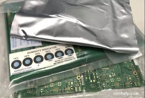
After the PCB is manufactured, it has a shelf life. If the shelf life is exceeded, the PCB needs to be baked. Otherwise, it is easy to cause the PCB to explode when the PCB is produced on the SMT.
Baking can eliminate the internal stress of the PCB, which is to stabilize the size of the PCB. The baked board has a relatively large improvement in warpage.
Advantages of baking: After baking, the moisture in the pad can be dried, the welding effect is enhanced, and the welding and repair rate are reduced.
Disadvantages of baking: The color of the PCB board may change, affecting the appearance.
The main purpose of PCB baking is to remove moisture and remove moisture from the PCB.
First, the specification of PCB management
1, PCB unpacking and storage
(1) PCB board seal can be directly used online within 2 months of unopened manufacturing date
(2) PCB board manufacturing date is within 2 months, the date of unpacking must be marked after unpacking
(3) PCB board manufacturing date is within 2 months, after opening, it must be used within 5 days.
2, PCB baking
(1) If the PCB is sealed and unsealed for more than 5 days within 2 months of the date of manufacture, please bake at 120 ± 5 °C for 1 hour.
(2) If the PCB is more than 2 months from the date of manufacture, please bake at 120 ± 5 °C for 1 hour before going online.
(3) If the PCB is more than 2 to 6 months from the date of manufacture, please bake at 120 ± 5 °C for 2 hours before going online.
(4) If the PCB is more than 6 months to 1 year before the date of manufacture, please bake at 120 ± 5 °C for 4 hours before going online.
(5) The baked PCB must be used within 5 days (input to IR REFLOW). After the bit is used, it needs to be baked for another hour before it can be used.
(6) If the PCB exceeds the manufacturing date of 1 year, please bake at 120 ± 5 °C for 4 hours before going online, and then send it to the PCB factory for re-spraying before it can be used.
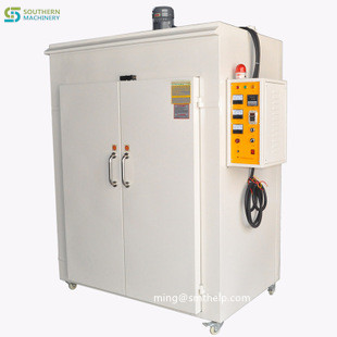
3, PCB baking method
(1) Large PCB (16 PORT and above including 16 PORT), placed in a flat format, with a maximum of 30 sheets in a stack, and the oven is opened within 10 minutes after baking. The PCB is placed in a flat and natural cooling (requires pressure to prevent the bay fixture)
(2) Small and medium-sized PCB (8PORT below 8PORT) is placed flat, the maximum number of stacks is 40 pieces, the number of uprights is not limited, the oven is opened within 10 minutes after baking, and the PCB is placed flat and naturally cooled (requires pressure protection) Banwan fixtures)
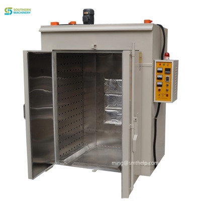
Second, the preservation and baking of PCBs in different regions
The specific storage time and baking temperature of the PCB are not only related to the production capacity and manufacturing process of the PCB manufacturer, but also have a great relationship with the region.
The PCB made by the OSP process and the pure immersion gold process generally has a shelf life of 6 months after packaging, and is generally not recommended for the OSP process.
The storage and baking time of PCB has a great relationship with the area. The humidity in the south is generally heavier. Especially in Guangdong and Guangxi, there will be “returning to the south” weather every year in March and April. It is very wet at this time. The PCB must be used up within 24 hours of exposure to air, otherwise it will be easily oxidized. After normal opening, it is best to use up to 8 hours. For some PCBs that need to be baked, the baking time is longer. In the northern regions, the weather is generally dry, the PCB storage time will be longer, and the baking time can be shorter. The baking temperature is generally 120 ± 5 ° C baking, baking time is determined according to the specific circumstances.
If you need to know more about PCB drying and PCB-baked-machine machin, please contact us.
Email:ming@smthelp.net Phone /skypy:+8618126316729
Southern Machinery (SMTHELP), which specializes in SMT machines and spare parts. SMTHELP has more than 20 years of experience in the electronics processing equipment industry. Customers all over the world, and win the trust and praise of customers. Long-term customers include BOSCH in Spain and India, DIXION in India, Panasonic in Mexico, Samsung and Cliptechin Brazil.
With the SMTHELP industry experience, philosophy and professional team, adhere to the “One-Stop Solution” belief to serve customers in the electronics processing industry, providing customers with cost-effective, high quality spare parts and equipment with stable performance from China, saving customers time And cost. truly one-stop solution services.
Automated optical inspection machine (AOI) is a new type of testing technology. It has
developed very rapidly in recent years. The structure of AOI consists of four parts: workbench, CCD camera system, electromechanical control and system software. When testing, firstly, the circuit board to be tested is placed on the workbench of the AOI machine, and the detection
procedure of the product to be detected is called out through positioning. The X/Y workbench
will send the circuit board under the lens according to the command of the setting program. With the help of the special light source, the lens will capture the image required by the AOI system and analyze it, then the processor will move the lens toward the lens. The next position is
collected for the next image and then analyzed, and the image is subjected to continuous
analysis and processing to obtain a higher detection speed. The process of AOI image
processing essentially digitizes the extracted image, and then compares it with the pre-stored “standard”. After analysis and judgment, it finds the defect to make a position prompt, and at the same time generates image text, and the operator further confirms or sends the repair station. Overhaul
Please call me to chat:
PCB Unloader \loader and Destacker from production to packaging.
1. Purchase all kinds of materials according to order.
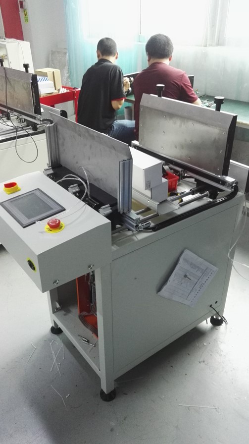
2. Frame installation of the entire machine.

3. Installed power motor
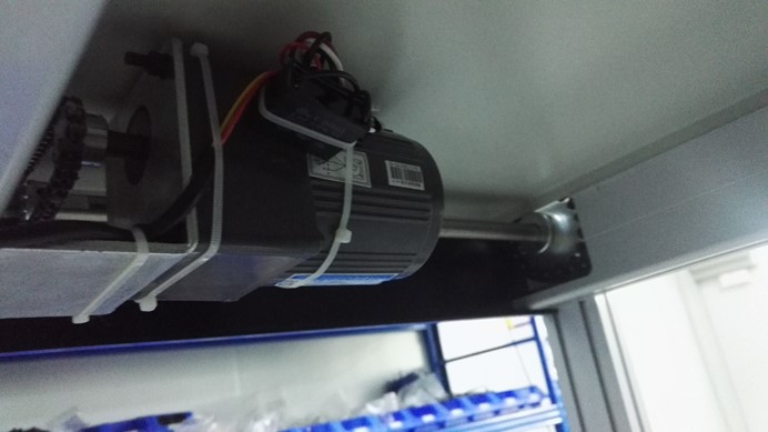
4. Install PLC control box.

5. Install sensor and belt.

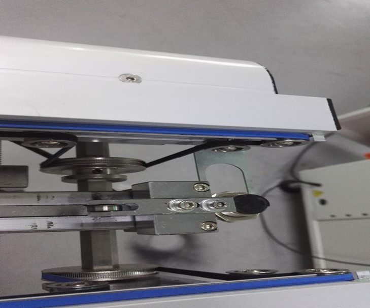
6.Install the cover
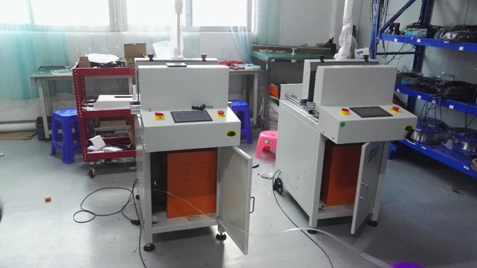
7.Install the LOGO

8. Install the program and test the machine.

9 .Use PCB board to test machine.
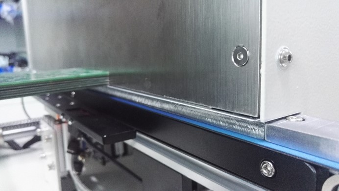

10.Use a magazine test machine.
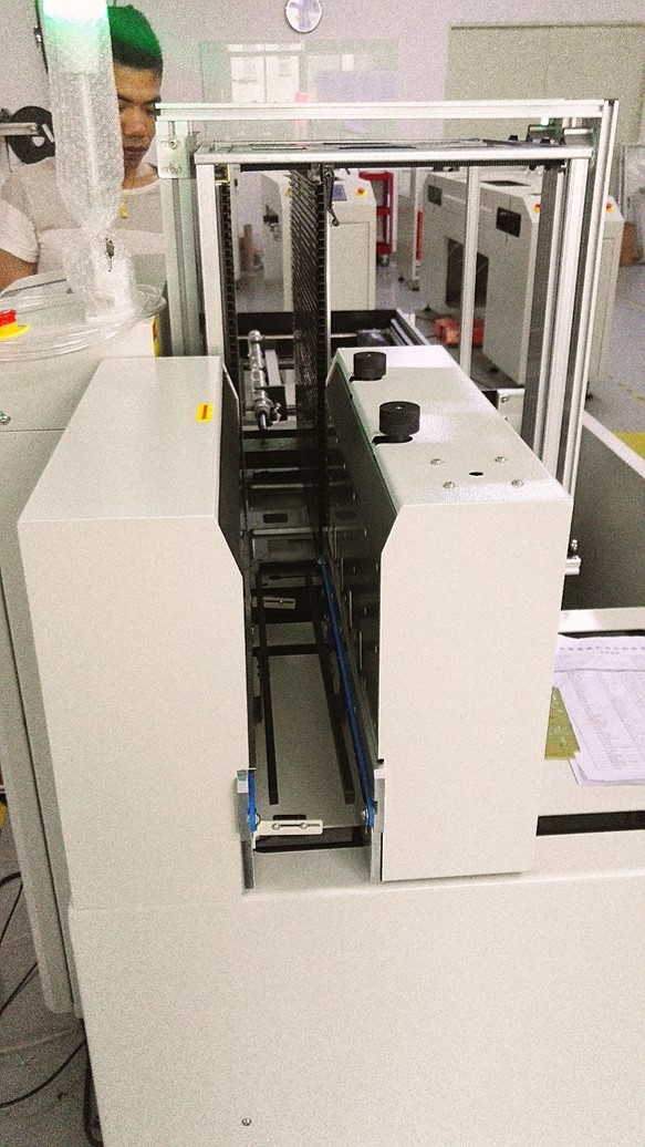
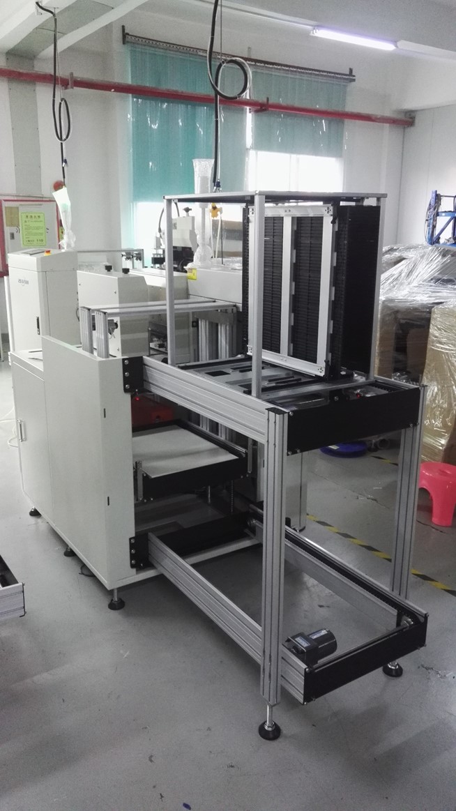

11. Aging operation week
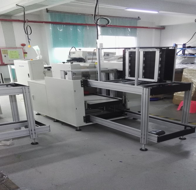

12. Simple packing before shipment.

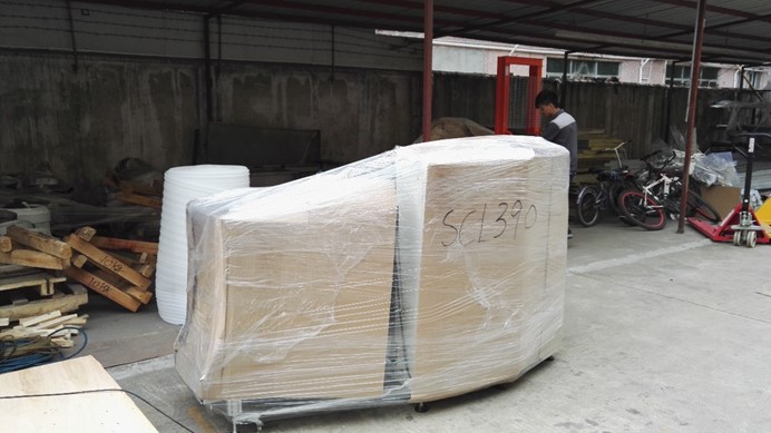
13. On the day of shipment, use the export wooden box vacuum packing,

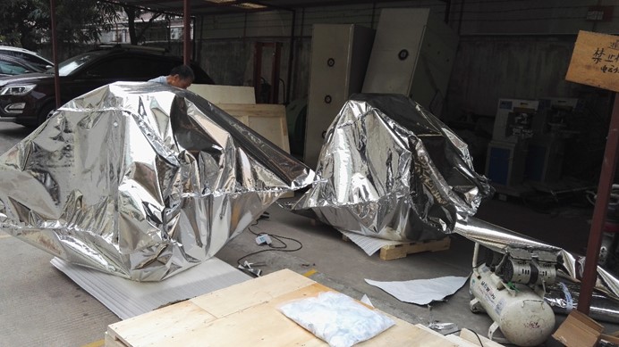

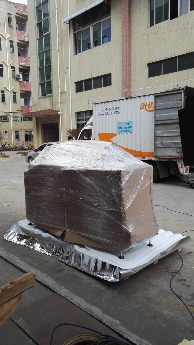

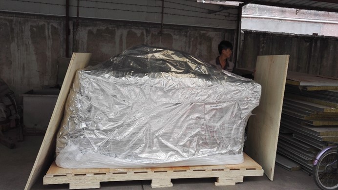


14. Arrange forwarders to pick up the goods.


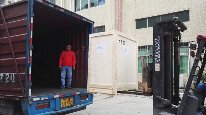
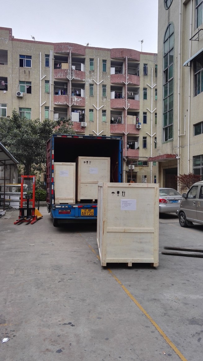
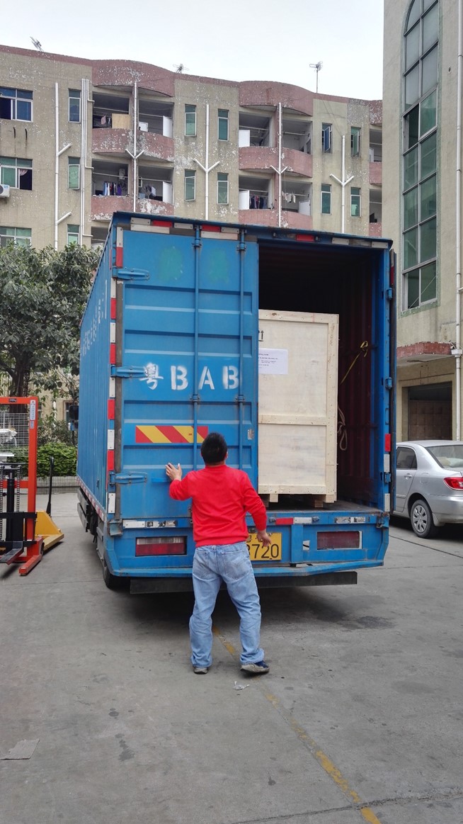

Four machines were shipped and shipped to the United States via freight forwarders.
ming@smthelp.com

45798407 Tube Continuity
45798406 Tube Continuity
45798405 Tube Continuity
45798404 Tube Continuity
45798403 Tube Continuity
45798402 Tube Continuity
45798401 Tube Continuity
Preventive Maintenance Schedule
WARNING Do not perform any preventive maintenance with power on unless specifically instructed otherwise. Failure to observe this warning may result in personal injury.
CAUTION When performing machine maintenance, wear a wrist strap connected to ground to prevent electrostatic discharge damage to printed circuit boards.
500,000 Cycles Check: Perform Maintenance:
3,000,000 Cycles Check: Perform Maintenance:
12,000,000 Cycles Check: Perform Maintenance:
Check for worn cutters and bushings on 1. Replace if necessary. the cut and clinch by observing the quality of the production board component leads. 2. Lubricate the clinch lead screw with Super Blue (BLKM07680). 3. Replace the O-rings and bumpers in the cutter cylinders on the cut and clinch assembly. 4. Lubricate the three surfaces of the notch in the rocker guide Kendall Super Blue (BLKM07680).
48,000,000 Cycles Check: Perform Maintenance: 1. Lubricate the anvil slides with Kendall Super Blue (40833838) and grease gun (47408201).


Automatic desktop SMT
pick and place machine
Model: S-6000V
Catalog

SMT system programming tutorial
Import PCB file coordinates directly and scraping PCB components coordinates manual.
① PCB coordinate document template, it is the CSV file.
 ②Open control system main interface – > file – > new file – > import coordinate.
③ The CSV file, PCB general has Top layer and Bottom layer element coordinates, please confirm the current PCB is the top layer or the bottom layer, choose in the lower left corner coordinates. Then click the lower right corner → the import button.
Import the coordinate file function instructions:
|
Import the coordinate file function instructions |
||
|
Option name |
Operation |
instructions |
|
Coordinate surface |
Choose the Top layer and Bottom layer to import coordinate components. |
|
|
Flip coordinate |
||
Select this option, will perform PCB flip horizontal coordinates
|
Flip Angle |
Option |
|
|
Allow Blank |
When coordinate file have the margin, import coordinate indicates a blank space, must be made to modify the file and then import, avoid programming error. Select this option, will ignore the coordinate file integrity, errors may result in mounting components. |


① X Y positioning equipment function
|
X Y positioning equipment function |
||
|
Option name |
Operation |
function |
|
drop-down |
||
|
options |
Option |
Choose the cursor, nozzle 1, nozzle 2 to grab positioning tool of the coordinate. |
|
Open cursor |
||
|
Close cursor |
||
|
Back to Home |
Execute |
Machine return to original state |
② Stepping set and X Y movement Function
|
Stepping set and X Y movement Function |
||
|
Option name |
Operation |
Function |
|
Stepping set |
Option |
Alternatively the step size of the X Y directions |
|
X Y movement |
Execute |
Up and Down, Leaf and Right button could Operate X Y direction positioning, In operation, please don’t close to the machine tool |
③ Manual input coordinate function
| Manual input coordinate function | ||
| Option name |
Operation |
Function |
| Bit No. |
Modify |
General is number, To manager the PCB program more clearly, fill the PCB current anchor element bit number. |
| Component Package | ||
| Center X |
Automatic acquisition |
Operation the movement direction key to the PCB component packaging center, Automatically obtain X Y coordinate value, please do not modified by hand. |
| Center Y | ||
| Angle |
Modify |
Angle of PCB component |
| Component Type |
Type of PCB component |
|
|
Note: After setting the above operation,, click “OK” to record coordinate current bit number. And then to do the next one. Directly to the center of the moving direction key to enter a number to setting, Click “OK” to finish record coordinate current bit number. |
||

|
Material stack configuration function |
|||
|
Option name |
Coil stock |
tray stock |
|
|
station number |
According to the material stack number |
||
|
Program Component |
Click and choice of material stack put components corresponding component model, choose components are not allowed to repeat |
||
|
Material System |
Click into the system of material select stack corresponding packaging material with configuration |
||
|
Component |
Click into the system components and system interface to select material with the corresponding system components package |
||
| Calibration center |
Click on the center coordinate values into the center calibration interface, moving XY direction calibration feed tray placed in the center of the stack and elements to get set up |
||
| Calibration broaching |
Click broaching broaching coordinate values into the calibration interface, moving XY direction calibration broaching center to get set up |
||
| Initial angle |
Material stack element display angle, the system default 90 ° degrees |
||
| Rows , columns line spacing, column space |
Modify the settings for each display from the ranks of the number and the element array tray material |
||
| Adapter nozzle |
2 head: left one is 1,the right one is 2, according to the different elements of the package material stack, could change any head. |
||
| Flight Speed |
Normal:30000pps, Special components can be customized flight speed. The smaller data , the slower operating speed |
||
|
More materia |
Pick up
speed |
Refers to the suction nozzle picking up speed, Normal: 20000pps. The smaller data , the slower pick up speed |
|
|
Pick up
Depth |
Refers to the suction nozzle distance with the end face contact material stack material when pick up the component, Through the calibration can get picked up depth data, Special component separately select pickup depth |
||
|
Pick up
alone |
To some special material stack, setting the speed the depth separately. |
||


| Multi-line batch modification Description | ||
| Description: Bit column number , hold down the left button to select a number of modifications can make the following batch modify. |
||
| Option Name |
Operation |
Description |
| Center X |
Modify |
batch settings calibration center X coordinate of material stack |
| Center Y |
batch settings calibration center Y coordinate of material stack |
|
| Broaching partial X |
batch settings Broaching partial X coordinate of material stack |
|
| Broaching partial Y |
batch settings Broaching partial Y coordinate of material stack |
|
| Pick up depth |
batch settings pick up depth of material stack |
|
| Adapter nozzle |
Option |
batch settings adapter nozzle of material stack |

| Material stack debugging tools, data checking function description | ||
| Option Name |
Operation |
Description |
| Material stack test |
Execute |
Pick up test for calibration finished material station configuration list |
| Save material station to the file |
Save the material station file for calibration finished material station configuration list, it could make it easy for the nest use. |
|
| Loading the material station from the file |
Can be loaded directly with the saved material station. |
|
| Check no material |
Check the Program Component in the material station configuration list for no material. |
|
| Check double material |
Check the Program Component in the material station configuration list for double material. |
|
| Check nozzle vacancy |
||

 Programming parameters automatically get in after the second material Stack Configuration.


① Click the Align program into the coordinate system origin correction interface.
② Calibration Make sure whether the splint placed parallel to the PCB in place, subject to the plywood base point, and then calibrate.
③ Calibrating the far two point coordination ( reduce the error), Click OK after finished
 calibrate.
Set Mark Point, choose a more independent square or circular Mark point as calibration points.( (Note: Mark point usage; in the fourth programming due to the PCB board or puzzle on the origin lead to error, click Mark point to automatic correct board )
Calibration is used to correct a separate placement coordinate with the actual Mark-point calibration.

 ① Reset the default placement coordination, mounting XY coordinate reply for source file coordination.
② Check invalid pick up material station, check whether the configuration is complete.
It can horizontal and vertical puzzle PCB.

① Manual correction: Click the PCB list of coordinates to enter the calibration correction, respectively coordinate 2 far point calibration.( reduce the error), If there is the puzzle PCB, then do the first PCB, and send and so no. The same way to calibrate.

 ② Mark point automatic correction: one-time auto-complete according to automatic Mark point on board.

|
Option Name |
Operation |
Description |
|
Base plate Depth |
Calibration |
Nozzle and plywood PCB contact distance, setting through the calibration. |
|
Optimization Option |
Option
Dual stepper reel, can improve the placement rate.
The default double election: if canceled a nozzle will not be placement relative programming can not be involved in SMT production process, two nozzles are canceled, the program
can not be generated.

|
Option Name |
Operation |
Description |
| Test mounting |
Option
Select the test mounting, roll feed zone does not feed tray,
please do not put components, SMT will simulate patch
End the process when
the error occurred
Selected, SMT work when other material stack error will end the current SMT all the work, and stop running
Speed Stalls
Set
The smaller stalls, The slower SMT run speed
Starting line number
It may be the current line number bit number for starting SMT
placement
Back Home
Execute
Back to initial state.
Start
Start SMT run
Pause / Resume
When SMT work, click this button, it could pause, and click
again, it could resume to work.
End
End the current work.

5.3 Mount coordination Preview
 Function: You can preview the imported PCB plots, red for the selected package components , it can zoom right to select the bit number to view the preview package management.


Nozzle Cleaning Machine
Operation Manual

Please read the instructions carefully before user operation
Preface
First of all, we sincerely thank you for choosing the SMT peripheral automation machine produced by our company. This company specialized production: conveyor, automatic feeding detection machine, vacuum suction machine, stacked on the machine, parallel transfer, angle conveyor, turning machine,machine, double buffer for the same reflow furnace system, a series of automated production machine. According to the customer’s requirements, we can develop and design a series of automation machine, in order to meet the customer’s high efficiency, energy saving, downsizing and other production needs. This manual describes the use of methods and machine maintenance and precautions, in front of the machine, please carefully read this manual, and it will be properly preserved, wrong operation may cause the device does not operate normally or damaged parts. Due to man-made machine failure or parts damage, will not apply to the company’s exemption free warranty service range. Without permission of the company, please do not disassemble or replace the machine parts, nor applicable to the company’s free warranty warranty service range. As to the improvement and partial renewal of the product, we will not make further instructions. If you have any doubts, please contact our company for consultation.
一、Important matters and safety instructions
When using this Cleaning Machine, you must abide by these safety devices.
All attention should be taken to avoid accidents and damage to the instrument.
1. please read and understand the user’s manual carefully before using or operating this machine.
2. non – instrument maintenance personnel and untrained personnel should not use this machine at will.
3. please avoid the use of this machine in the vicinity of the strong electromagnetic interference source.
4. please avoid the use of this machine in the environment with high humidity.
5. maintenance, please turn off the power, to prevent damage to components.
6. instruments are used, they should be kept stable to prevent falling.
二、Appearance introduction

1、Liquid storage tank:
When the cleaning liquid is completely unused, the liquid can be added, and the addition method is referred to the addition of the solution step.
2、Emergency switch:
After pressing the emergency switch, PLC is out of power and the equipment stops working
6、Storage tank:
Store the cleaned liquid and put out of the liquid in time.
Step: the tank is pulled out, carefully put out the liquid.
三、Operation steps
1. connect the power supply (220V, 50HZ) and gas supply (0.6MPa), turn on the power switch.
2.Check whether there is a liquid on the left level (the grooves pipe), if it‘s no,then add liquid (detailed please refer the step of adding the liquid).
3. Switch is normal opening , and the touch screen appears as the Figure 3.1 interface

Figure 3.1
4. Click Figure 3.1 [into system], and appear on the interface, such as Figure 3.2. If you need to set parameters, enter the manual tool interface for parameter settings (detailed please refer the parameter settings).When you set it up, Hit [save parameter].

Figure 3.2
Note: first use the parameters set first ( refer parameter settings) and then do the next step.
5. When nozzle is placed well,closed the door tightly ,and set the parameters(can skip). Confirm that the suitable angle is adjusted well, that is, the nozzle is aligned with the suction nozzle center, otherwise it can’t be cleaned.
6. Click Figure 3.2 [reversion], then click Figure 3.2 [auto start] (after click finish is displayed as automatic stop) or press the boot button of the device
1. click the [manual tool] as shown in Figure 4.1, as shown in Figure 4.2
Figure 4.3
Input signal monitor(click the interface of Figure 4.2 [ input and monitor].)
Figure 4.4
Manual control interface(click the interface of Figure 4.2 [ control debug].)
Use in manual debugging

Figure 4.1

Figure 4.2

Figure 4.3

Figure 4.4
2. click on Figure 4.2 [parameter settings], appear as shown in Figure 4.5, according to actual needs, set up relevant parameters, click figure 4.5 [bottom parameter], the password is 4 “8888”, and then appear as shown in Figure 4.6.

Figure 4.5
1) nozzle: set the number of nozzle (according to the jig can install the number of nozzle to set)
2) clean time: setting up a single nozzle cleaning time (according to the actual situation)
3) air-dry time: setting the time to complete the air-dry of a single nozzle (according to the actual situation)
4) save parameter: after setting the complete parameter, you need to click the [save parameter].

Figure 4.6
1) Original correction: to confirm the suitable angle, that is, the angle of the nozzle and the nozzle center to be rearranged, and the setting is set up.
2) Power on air storage time: set according to the actual situation
3) Air storage time before clean: it refers to the setting of the gas storage time before each cleaning, according to the actual situation.
4) Interval air storage time: express the later that later chose not to select the display as “yes”, For example, the clean time is 3 S, and interval air storage time is set to 1S, after cleaning 1S, gas storage for 1 S, and then clean for 1 S.
5) Impulse quantity: it express the impulse quantity for the turn of the turntable to 1o. If the device is not at its origin, it will increase the impulse quantity if it arrives at the origin. If it is found that the device is not at its origin, if it exceeds the origin, it will increase or decrease.
6) Continuous jet: express choose whether to continue the actual situation as yes” no choice later, shown as “no” is that he has chosen to continue.
1. after the start of the machine,enter the standby state and enter the interface shown in Figure 5.1.

Figure 5.1
2. click [pressure relief] has been holding down the nozzle, until no gas ejected and then release the hand off power.
3. open the tank cover, a funnel into the washing solution until close to the reservoir until canful.
4. closed storage tank cover, power off, re-work.
Note: the cleaning solution will never be allowed to splash into the equipment, otherwise the controller will burn out.
六、Daily maintenance project
| Time |
Maintenance project |
| Daily | the water must be emptied after each use. |
| the water must be cleaned up on the platform after each use. | |
| Weekly | check whether there is water leakage in the pneumatic cabinet and electrical cabinet. |
| check the looseness of the screws in each movement mechanism. | |
| check whether the external electrical connector is loose. | |
| cleaning the dust and debris in the electric cabinet and the pneumatic cabinet. | |
| check the air leakage of the pneumatic components and the joint of the trachea. | |
| Monthly | check the oil mist special oil in the oil mist is too small, less is added. |
| check whether the internal joint of the electric cabinet is loose. | |
| check the entrainment wheel, whether the belt wear out. | |
| lubricating grease for all bearings of each device. |
Meet the Needs of the SMT Age
Please read this user manual carefully before running

S-1688 Stencil Cleaner Machine
USER MANUAL
TEL : 0755-83203237
FAX : 0755-23240492
ADD : Room 1806, Block 3, Jinyun COFCO, Qianjin 2nd Road ,Baoan District,
Shenzhen City, China
CONTENTS
1.0 safety warning……………………………………………………………………………….3
2.0 product presentation
…………………………………………………………………3
3.0 installation requirements……………………………………………………………….4
4.0 Operations Guide……………………………………………..…….………………………………..5
5.0 The cleaning of the solvent is added, platoon and storage tank………………………………………………………..………….…………………………………………..13
6.0 Replacement of filter element………………………………………………………15
7.0 Product use precautions……………………………….…………..……………….…………………………………..16
8.0 working principle………………………………………….………………………………………..16
9.0 Maintenance, fault handling ……………………….………………………………………16
1.0 safety warning
1.1 Please read this manual carefully.
1.2 Please strictly follow the installation requirements in this instruction and the guide to operation. The installation and use of this equipment.
1.3 Please equip a person to operate the equipment
1.4 The operator must wear protective glasses, protective gloves, protective respirators and other protective products.
2.0 product presentation
2.1 Name: full pneumatic steel net cleaning machine
2.2 model: S-1688
2.3 Product features
1)
Use full pneumatic logic control, one-click operation, easy to finish cleaning and drying
2) No power supply, no fire hazard.
3) The cleaning frequency system is automatically counted to facilitate the replacement of consumables in time to ensure the quality of cleaning work.
4) The cleaning pressure can be adjusted according to the need to ensure the stability of steel mesh tension, thus ensuring the longer service life of the steel net.
5) The whole operation process is completely closed, avoiding the direct contact between the workers and the cleaning fluid
6) Various types of cleaning fluid can be used for efficient cleaning
7)
Can effectively remove solder paste, such as red glue residue and more from steel mesh, wire mesh, copper mesh, microporous network, scraper, fixture, PCB, etc.
8) The three – level filtration device ensures the recycling of cleaning fluid, and realizes the minimal loss of cleaning fluid.
9)
Asymmetric rotating spray arm: ensure the cleaning of fine PCB holes.
10)
Digital free setting cleaning and drying time
2.5. Main technical parameters:
| Application | stencil, glue screen , copper screen |
| Stencil size | Standard 29 inch and below |
| Clean liquid capacity | Max 50L , Min 20 L |
| Cleaning fluid volume | 40L |
| Cleaning method | Rotary double-sided pressure injection and high-pressure air spraying ( cleaning and drying ) |
| Clean time | 2~4 min (stencil and copper net) |
| Rinse time | 2~4 min (stencil and copper net ) |
| Dry time | 2~5 min |
| External air supply | 0.4Mpa~0.6Mpa |
| Air consumption | 400~600L/Min*2 |
| Air outlet size | ?125*25mm |
| Weight | 320Kg |
| Dimension | 980mm(L)*700mm(W)*1730mm(H) |
| Tin filter method | Three class filter (10?m,5?m,1?m) |
3.0 installation requirements…
3. 1. Installation site
In order to ensure safe production and prevent possible damage to the equipment, the equipment should be installed in a place that meets the following environmental conditions
1) Stay away from sources and heat sources
2?The air is dry and well ventilated
3) Clean, clean, flat and unshaken ground
3. 2. Installation accessories, required energy and precautions
1) The source pressure is : 0.4Mpa~0.6Mpa
2)Taken the air over diameter for ?: 12mm, a quick joint is needed
3) The top of the equipment is designed ?: The 125mm exhaust port shall be connected to the outside by independent air duct
4) matters need attention: In order to ensure safe production, customers must ensure that the following security measures are installed in place. Otherwise, the company does not assume any responsibility for security
?It is at least 3 meters away from the electric equipment, away from fire source and heat source
?The ground wire must be connected, and the earth shall not be connected to any other electrified equipment
?The exhaust duct of this equipment shall not be connected to any equipment that can produce heat source. (such as reflow soldering wave soldering of SMT, etc.)
3.3 installation space
To facilitate the maintenance and replacement of spare parts for equipment operation, please leave more than one meter space around the equipment
4.0 Operations Guide
A Preparation before operation
4.1.1 connect the air source to the machine, the gas source is connected well, the display lamp is highlighted and the subsequent work can be continued
4.1.2 check if air pressure in the standard rating (04-0.6 MPa) range. Lower than 0.4mpa will affect the cleaning effect and reduce production efficiency (too low will not activate the machine).
Higher than 0.6mpa can result in damage to the mechanical gas system and all parts of the system.
Adjust the pressure method: pull upward gently to adjust the knob and rotate to the right————- Increase pressure
Go to the right ————– reduce stress
After reaching the required pressure, press the adjusting knob, air pressure lock and pressure to complete the gas connection, and the lamp is highlighted


4.1.3 check whether the top exhaust duct is unblocked or unblocked, which will result in damage to the environment and other consequences of the cleaning effect
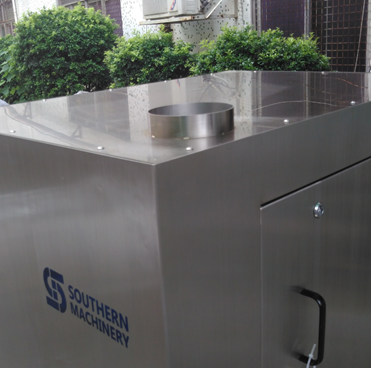
4.1.4 check the glass viewport of the door panel through the liquid road to check the solvent reserves. The normal state is above the M position, and the machine can meet the various cleaning effects. The amount of liquid stored in this model is the maximum amount (40L).

4.1.5 if the solvent is not enough, please add adding method in time: see adding solvent method
4.1.6 the pump access panel is opened with a randomly attached triangle key to check whether the ball valves are in normal condition
Ball (the ball valve of pump outlet filter) A ball valve D (pump inlet connection of the reservoir fluid Xiang ball valve) opens, B ((the ball) of white PE tube pump discharge ball valve C (white PE tube pump inlet ball valve) closed


4.2 time setting
4.2.1The setting of the cleaning time (see figure below), gently rotate the timer protection cap to the left and pull up the cover.
General cleaning time is
Minutes, depending on the actual situation, will be different.
This timer is measured in seconds (S) with a range of 10-999 seconds (S).
It can be set to 0, otherwise the machine will not start and may damage the timer and other components.

4.2.2 setting of drying time
Operation method and cleaning time setting.
The general drying time is 4-6 minutes depending on the actual situation.There will be an elongation of the aqueous solvents.
4.2.3The cleaning and drying time are automatic reset.
That is, one set, multiple times (N times).
When the pressure is less than the required number, the timer can be reset and the device cannot be started.
At this point, the black reset button on the upper row of the timer can be reset manually.

4.2.4The counter’s use of this counter is the increment counter, each cleaning a steel net, automatically into the system,
One of them is going up.
The count range is 0-999999.
Mainly used for cleaning work statistics, timely replacement of consumables (filter element), etc.
The filter cartridge should be changed when cleaning up to 1500.
Specific visual cleaning products are different and different.
When the counter displays the number to reach the target number, press the 4.2.3 method to open the cover, then press the black reset button on the left of the timer and the counter is reset.
4.3 placement of steel mesh
4.3.1 press the inner door safety button to open the cleaning room

4.3.2 lift the steel net with http://topmednorx.com both hands, gently place the front in the cleaning room chute roller and push it gently forward to the sliding channel steel
Fixed fixture on the net.
The steel net is in the middle of the fixture and chute. The top of the steel net is at the top of the cleaning room
Steel mesh fixture middle.(see below.)

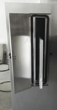
4.3.3 when placing the steel mesh, the steel mesh shall not be in contact with the door to avoid damaging the steel net and sealant

4.3.4After the steel net is placed, close the cleaning door.
The inner door should be kept in good condition, otherwise, the solvent will be expelled outside, causing machine damage or environmental damage, more likely to cause personal injury

4.3.5 after the inside door is closed, continue to close the outer security door.
The security door is closed and the light is on, so that the following operation can be continued.
If the security door is not closed, the lamp will be retracted and the machine will not be able to start.
After closing the door again, the machine can be started

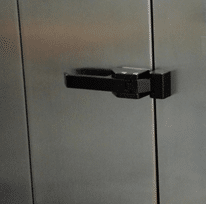
4.4 the start of the machine
4.4.1 press the start button lightly and the machine will start to run.
The machine will be automatically restored until the cleaning is completed

4.4.2 use the emergency stop button to press the emergency stop button when the emergency situation is in place. The machine will stop running.
The emergency situation is eliminated and the machine is restarted


4.5 adjustment of cleaning pressure
After the machine starts, pay attention to the pump input air source pressure and output cleaning pressure.
In order to achieve the best cleaning effect and maintain the tension of the steel mesh, the pressure should be adjusted

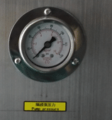
4.5.1 pump input air source pressure is generally maintained at about 0.4mpa
4.5.2 cleaning pressure is generally maintained at about 0.2-0.3MPa

4.5.3 adjustment of pump pressure: gently pull the adjusting knob of the pressure-reducing valve and turn the pressure on the right to increase the pressure to the left.
After adjusting well, press the adjusting knob to lock and adjust the work.
Note: this valve is the pressure reducing valve, the pressure adjustment will not be higher than the air source

4.6 the setting time is terminated and the machine is automatically stopped.
A cleaning cycle is over
5. Add, drain, and container for the solvent
5.1 addition of solvent
5.1.1 let the machine stop and open the access panel.
5.1.2 close ball valve B, D, open ball valve A, C.
Insert the “IN” pipe IN the ball valve C into the container containing the solvent.
Control the “IN” tube and start the machine until the machine drains the solvent.

5.2 discharge solvent and storage tank cleaning
5.2.1 open the liquid access panel and start the machine according to the normal procedure.
Close the ball valve D, open the ball valve C, and leave the machine idle for 1 minute.
In order to take out the solvent in the filter.
5.2.2 Open 8 screws on the tank and remove the reservoir cover..
5.2.3 press the stop switch to stop the machine.
Close the ball valve A and C, insert the “OUT” pipe of ball valve B into the container and slowly open the ball valve D.
Take care to control the “OUT” pipe at this time so as not to cause an accident.
5.2.4 when the solvent location of the reservoir is lower than the outlet filter of the reservoir, close the ball valve C and open the ball valve D.
Insert the white PE tube into the storage tank to remove the remaining solution
5.2.5When the solvent is removed, loosen the filter to fix the wire, remove the filter bag, remove the filter of the outlet and clean it with water or other means.
When the storage tank is cleaned and reloaded, cover the tank and lock the container
5.2.6 the liquid storage tank shall be cleaned and the solvent shall be drained and the machine shall be turned off.
Use a shovel knife to clean up the thick residues, leaving the small residue with a cloth strip
5.3 precautions for solvents
5.3.1 please wear protective equipment, such as protective gloves, protective glasses, protective masks, etc. to avoid direct contact with the human body and affect health and other safety accidents.
When operating, please pay special attention to the “IN” and “OUT” piping that controls the activity so as not to cause unnecessary security
6. Replacement of filter element
Replace the filter cartridge when cleaning a certain amount of steel net, the filter element needs to be replaced to satisfy the cleaning effect.
The replacement method is as follows
6.1. Remove the bottom of the filter with the left hand of the filter and remove the wrench into the disassembly hole, rotate the wrench to the left, remove the filter, then remove the filter element


6.2 installation of filter element
Wipe the filter clean and put in the new filter. (note that you can install a 5-micron filter on the outside by installing a 1-micron filter.
Then the left hand holds the bottom of the filter, and the right hand moves the filter nut.
When the hands are wrung, remove the wrench and hold it until it is unscrewed.
Pay attention to the filter cartridge when operating, the position of the filter should be put in place, for the positive
6.3 Replacement of seal rings
The sealing ring of the filter shall be soaked in the solvent for a long time because the chemical function will become larger. When the filter is removed, it will be difficult to install again.
The sealing ring should be removed at this time, with the spare ring installed.
Close the sealing ring after getting bigger, and substitute elastic back for backup
7. Use precautions
7.1. The installation site of the equipment is strictly prohibited near the source of fire, heat source and power supply.
The ground wire and exhaust duct must be installed and installed completely independently. It shall not be connected or connected with any other equipment
7.2. Replace the solvent, add, discharge the solvent, change the filter core, and when the steel net is taken, please wear protective equipment.To ensure the operator’s health and safety accidents.
7.3. Require strict access, adjustment and use of air source pressure according to the rated standard.Operate the machine according to the operating instructions and procedures of the machine.
7.4. It is not possible to bring cloth, paper scraps or other sundries into the machine cleaning room, or leave it in the storage tank, or it may cause blockage of the pipe and damage to the machine.
7.5. When operating the machine, please pay attention to the moderate intensity to avoid damage to the machine components.
7.6. No solvent cleaning machine surface or other non-stainless steel components shall be used to ensure the service life of the machine
8. Working principle

9.0 maintenance and fault handling
9.1 maintenance

9.2 fault handling

