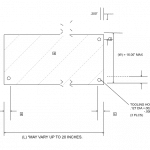
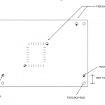
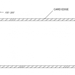
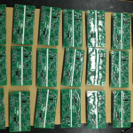
Electronic Manufacturing THT component Clinch Tooling to SMT Clearance (Bottom side)

All PCBs will be designed with the following preference guidelines for choice of components, placement, and track size. This strategy is intended to make maximum use of Design and Manufacturing capabilities and to minimize overall manufacturing costs:

  1. Full SMT. Component side only
  2. Full SMT. on both Component and solder sides
  3. Mixed SMT. and pth. on component side only
  4. mixed smt. and pth. with active smds on the component side and passive components on solder side

Clinch Tooling to SMT Clearance (Bottom side)

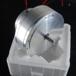
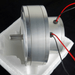
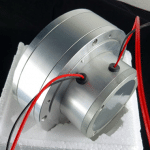
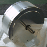
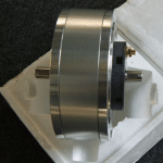
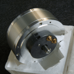
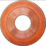
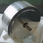
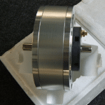
Universal Auto insertion machine X Y motor – U12DNUA/S6T,42418104

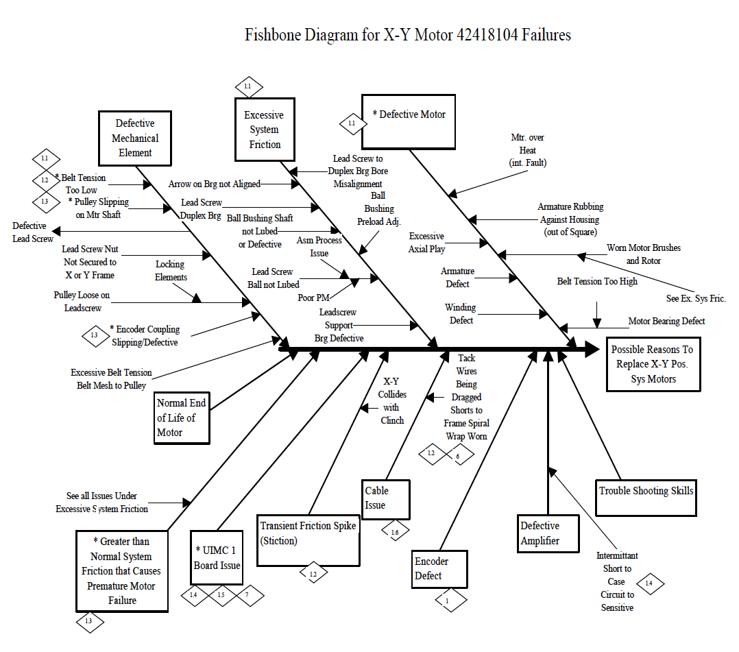
BrushedMotorX-YPositioningSystemMotionFaultDiagnosticProcedure

The following procedure is intended to be used as a diagnostic tool for determining general causes for X Y Positioning System Motor failures and Motion Faults. Using a known good motor, an attempt will be made to isolate the problem between there motor, or the other system issues. UsethisprocedureonlyonGeneration8,SingleHeadMachinesequippedwithBrushedMotors(referencepartnumber42418104).

Note:
Ifyouhavetoreplacea Motor, pleasereturnittoBinghamtonintheboxthereplacementcomesin.

EQUIPMENT NEEDED:
Good Motor, Blue Kendall grease (40833810) for leadscrew, 10W (40833827) oil for ball bushings & axis shafts, Phillips head screw driver, Allen wrenches

F/E SKILLS REQUIRED:

IM Diagnostics
X-Y Home Zero Set-up
Installing X-Y Positioning system motors

ESTIMATED TIME TO PERFORM PROCEDURE:
30 minutes if no problems found
3 hours if motor is found to be defective
5 + hours if other system problems are found INFORMATION (please fill out)

STEP1(PerformonXaxisfirst,thenrepeatonYaxis)

In this step, you will be running a single axis at reduced speed & acceleration while observing the Max DAC output, which is proportional to the torque. If the torque is too high, this may indicate motor or positioning system problems.

LAUNCH IM DIAGNOSTICS

Run “Quick Start” Select #1 “Set-up BEC”
When macro is done zeroing (quit don’t save) to exit “set-up BEC” screen

Select: DIAGNOSTICS, MANUAL DIAGNOSTICS
On the LEFT side, click the pull down menu of the “SECTION” box. Select “UIMC 1 AXIS INPUTS”
Click the BLUE “MOVE” button & edit the following parameters: Speed from 116 to 10
Acceleration from 2400 to 500

Click the Auto Cycle & Continuous Run check boxes Cycle the axis from 0” to 18” or 0 count to 144,000 count
Observe the “Maximum DAC Output During Move” number for approximately 5 minutes and fill out the STEP 1 CHART below.
If the number ever gets above 340 maximum, the system has too much friction. It could be the motor or other system problems.
If the “Maximum DAC output during move” is less than 340. Stop. No further steps are required for this Axis.
This Axis appears to be functioning correctly.

STEP1CHART
Proceed to STEP 2
STEP 2
In this step you will perform specific PM activities that have a large impact on the amount of torque required to
operate the positioning system.

Grease the lead screw, oil the shafts & re-tension the belt.

Cycle at normal speed and acceleration for ½ hour, check the appropriate box below.

Speed…………116 Acceleration….2400

Was theleadscrewdry? YESĀ NOĀ
Was theShaftdry? YESĀ NOĀ
Was thebeltloose? YESĀ NOĀ

Cycle at the reduced Speed & Acceleration per STEP 1 and fill out the STEP 2 CHART below. If it gets considerably better (Max DAC below 340) you’re done. If not, go on to STEP 3.

STEP2CHART

STEP 3

In this step you are removing the motor in preparation for Step 4 and making further investigation into possible sources of high positioning system friction.

Remove the motor and move axis by hand.
Feel and listen for binds, hesitations or noises in the lead screw and/or ball bearing/shafts.

Whatwasfound?

Check axial play/gap in the lead screw by grabbing it by hand & pushing in both directions. There should be no perceivable axial play in the leadscrew.

MaxDACOutputDuringMove

MaxDACOutputDuringMove

Was thereanyplay? YESĀ NOĀ
Replace any parts that you think it has problem.
Whatwasreplaced?
PartNo Description Symptom

Universal Auto Insertion machine X, Y Motor Maintenance Procedure

Purpose:

The purpose of this document is to describe how to maintain the “Gold” series motors, PMI type U12M4, and U12M4H (UIC part number 11467000, 13570000, 40051001, and 40051002, sold before November 1995) This procedure should be performed every six months, or more frequently if found to be necessary.

Tools Required:

Allen wrenches
Screw driver (5 to 6 mm wide)
Screw driver, small blade (2,5 to 3 mm wide)
Adjustable wrench

Prerequisite:

Push in the machine’s Emergency Stop button
Turn off the machine’s power

Procedure:

1. Note which wires are attached to which motor terminal. Using an adjustable wrench, remove the wires from the motor’s terminals.

2. Remove the motor from the machine

3. Remove the brushes from the motor

4. The minimum usable length of the carbon part of the brushes is .240 inches ( 6,1 mm) long. If the brushes wear shorter than .240 inches, the motor’s commutator wires can be damaged by electrical arcing.

So that the brushes will not wear to less than .240 inches, we recommend that they be replaced when they become .300 inches long ( 7,62mm). Universal’s part number for a set of four (4) brushes for these motors is B26100021.

5. Check that the motor’s shaft turns smoothly. If not, then the bearings are damaged, and the motor should be discarded.

6. Using clean, dry, compressed air, blow the carbon dust out of the motor.

7. Look through the brush holes and examine the condition of the commutator wires, while turning the motor ambien shaft. If there are any burned or damaged wires, the motor must be discarded.

8. To install the brushes into the motor, place the carbon block in the brush hole.

9. Using a small screwdriver, gently push the spring down into the brush hole. It will be necessary to reposition the blade of the screw driver several times into the coils of the spring, to make the spring go into the hole.

10. It may be necessary to push the metal tab on the side of the brush contact to make it go into the brush hole.

11. After the metal tabs have gone into the hole, use the screw driver to hold the brush contact down in the brush hole.

12. Pull the small screw driver blade out while moving the screw into place. Be sure that the brush contact’s tabs do not come completely out of the brush hole when doing this. Start the screw in the threaded hole by turning it clockwise with your fingers. If it will not turn easily, remove it, and repeat step 11. Then tighten the screw gently using the large screw driver.

13. Install all (4) brushes into the motor. Mount the motor on the machine again. Reattach the wires on to the proper motor terminals.

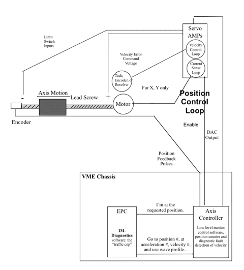
Machine Axis Control IM-Diagnostics Mode Overview *
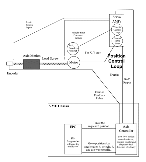
*This is a generic overview for training purposes. Actual axes on the machine may differ slightly from this overview.

Universal Auto Insertion machine X, Y Motor Maintenance Procedure

Purpose:

The purpose of this document is to describe how to maintain the “Gold” series motors, PMI type U12M4, and U12M4H (UIC part number 11467000, 13570000, 40051001, and 40051002, sold before November 1995) This procedure should be performed every six months, or more frequently if found to be necessary.

Tools Required:

Allen wrenches
Screw driver (5 to 6 mm wide)
Screw driver, small blade (2,5 to 3 mm wide)
Adjustable wrench

Prerequisite:

Push in the machine’s Emergency Stop button
Turn off the machine’s power

Procedure:

1. Note which wires are attached to which motor terminal. Using an adjustable wrench, remove the wires from the motor’s terminals.

2. Remove the motor from the machine

3. Remove the brushes from the motor

4. The minimum usable length of the carbon part of the brushes is .240 inches ( 6,1 mm) long. If the brushes wear shorter than .240 inches, the motor’s commutator wires can be damaged by electrical arcing.

So that the brushes will not wear to less than .240 inches, we recommend that they be replaced when they become .300 inches long ( 7,62mm). Universal’s part number for a set of four (4) brushes for these motors is B26100021.

5. Check that the motor’s shaft turns smoothly. If not, then the bearings are damaged, and the motor should be discarded.

6. Using clean, dry, compressed air, blow the carbon dust out of the motor.

7. Look through the brush holes and examine the condition of the commutator wires, while turning the motor shaft. If there are any burned or damaged wires, the motor must be discarded.

8. To install the brushes into the motor, place the carbon block in the brush hole.

9. Using a small screwdriver, gently push the spring down into the brush hole. It will be necessary to reposition the blade of the screw driver several times into the coils of the spring, to make the spring go into the hole.

10. It may be necessary to push the metal tab on the side of the brush contact to make it go into the brush hole.

11. After the metal tabs have gone into the hole, use the screw driver to hold the brush contact down in the brush hole.

12. Pull the small screw driver blade out while moving the screw into place. Be sure that the brush contact’s tabs do not come completely out of the brush hole when doing this. Start the screw in the threaded hole by turning it clockwise with your fingers. If it will not turn easily, remove it, and repeat step 11. Then tighten the screw gently using the large screw driver.

13. Install all (4) brushes into the motor. Mount the motor on the machine again. Reattach the wires on to the proper motor terminals.

Machine Axis Control IM-Diagnostics Mode Overview *

*This is a generic overview for training purposes. Actual axes on the machine may differ slightly from this overview.
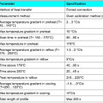
SMT Reflow soldering process specification for electronic manufacturing PCBA

  • Reflow soldering process specification
  • Profile measurement equipment

Reflow profile shall be measured using a temperature measurement equipment specifically designed for pass-through reflow profile measurements.

The profiling equipment shall be calibrated regularly according to the maintenance instructions by the supplier.

Only the thermocouples recommended and approved by the measurement equipment supplier shall be used.

Reflow profile measurement method

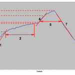
Reflow profile specification

Figure 1. Illustration of critical reflow process parameters.

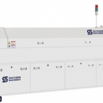
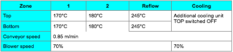
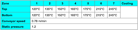
Recommended reflow oven settings

The following settings shall verified for each oven using oven calibration method (section 6.2) and settings shall be adjusted if necessary to achieve a profile within the specification in section 6.3.

ERSA Hotflow 7

BTU VIP98

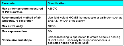
MANUAL SOLDERING PROCESS AND WORKMANSHIP CRITERIA

  1. Manual and semi-automatic hot gas soldering and rework

Warning! A visual change in PWB surface characteristics during heating is a sign of too high a temperature and/or too long exposure time and must result in rejection of module.

Lead-free & Good quality & Cheap Solder Paste

Product Description

This solder paste special for SMT production process. It is made from the special solder paste and sphere tin power with little oxide content. It has the excellent performance in continuous printing. It has very little residue after reflow and very good insulation impedance. With various alloy composition, different diameter of tin powder, and metal content to meet the customer need in products and process requirement.

Product Feature and Selling points                                                                                                           

  1. 1.    Good http://shopantibioticsonline.com rollability in printing, excellent performance in printing even for 0.3mm part spacing in steel plate.
  2. 2.    Little changes for the viscosity for continuous printing, longer life time for the stencil, and good printing performance even for continuous 8 hours printing.
  3. 3.    No slump electron migration several hours after printing.
  4. 4.    Excellent welding performance and proper wettability in different parts.
  5. 5.    Adaptable to different level of welding equipments, finish welding with no nitrogenization, good performance in welding even in wide range reform temperature.
  6. 6.    Very little residue, light in color, and good insulation impedance and no corrosion to PCB, no need clean.
  7. 7.    Good testing performance in ICT.
  8. 8.    Workable for paste in Hole process
  9. Solder paste3 Solder paste6 Solder paste2 Solder paste1 Solder paste IMG_2792

Solder paste Printing process parameters (stencil printing) for Electronic Manufacturing PCBA

Printing process parameters (stencil printing)

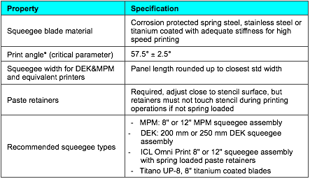
Parameter Setting
Print speed 100mm/s recommended, min 70mm/s, max 120mm/s

Note: Under non-conforming situations caused by technical problems, lower than specified speeds are temporarily accepted.

Squeegee pressure for 200mm wide squeegee** in constant force mode (force automatically adjusted, print head floating) minimum pressure that will wipe stencil surface clean +5N as safety margin, normally between 40 50 N
Squeegee adjustment for MPM printers (constant squeegee distance (negative) from PWB surface, force against down stops) Minimal adjustment that will wipe stencil surface clean +0.5mm as safety margin
Snap-off distance -0.5 – 0.0mm on whole panel area (negative snap-off recommended to give margin against machine misadjustments)
Separation speed Max. 20 mm/sec until stencil has released, then maximum speed.
Automatic wipe rate After every 10 ± 5 prints Note: Under non-conforming situations caused by temporary technical problems more frequent wipe may be applied.
Wipe cycle recommendation 1 dry with vacuum or 1 dam followed by 1 dry for printers without vacuum option
Recommended cleaning fluid for printer automatic wiping Multicore Prozone SC-01 or equivalent high flash point solvent officially accepted by printer manufacturer. Use of isopropanol (IPA) or equivalent solvents is not recommended due to fire safety.
Recommended cleaning fluid for cleaning of misprinted boards Multicore Prozone SC-02 is preferred (SC-02 will attack slightly acrylics and some rubbers used in protective gloves)

Use of isopropanol (IPA) is allowed but not recommended. Waste must be handled properly.

Note! Components that are not designed for liquid cleaning process, have to be removed and changed after cleaning.

PWB with laser (micro) vias, OSP plating or which are totally or partly Aramid based, ARE NOT ALLOWED TO BE WASHED! Cleaning solvent traps into PWB structures and reduces esp. CSP components joint reliability.

Support table vacuum OFF while printing, unless dedicated workholder is of such construction that no vacuum is created between PWB and stencil OR vacuum is limited to 100-200mbar. Vacuum ON during loading and table movements (activate special 1043 in AP-25 SW 6.1 or later).
Kneading1 8 kneads after every 20min or longer pause in printing process and recommended after addition of paste. Otherwise not needed.
Solder paste amount on stencil 150 160 g + paste attached to squeeze (200mm )
Printing accuracy +/- 0.05 mm

*) Sometimes referred as ”squeegee pressure” and force given in KGs, 1kg=9.81N

**) Depends linearly on squeegee width

1) Automatic procedure to soften paste and dissolve partly dried paste residues at stencil aperture opening edges instead of stencil manual cleaning. The panel used for kneading can be fed to production line as normally printed board. After pauses beyond 120min careful stencil cleaning in dedicated cleaner is recommended.

Solder paste Printing process parameters (stencil printing) for Electronic Manufacturing PCBA

Printing process parameters (stencil printing)

Parameter Setting
Print speed 100mm/s recommended, min 70mm/s, max 120mm/s

Note: Under non-conforming situations caused by technical problems, lower than specified speeds are temporarily accepted.

Squeegee pressure for 200mm wide squeegee** in constant force mode (force automatically adjusted, print head floating) minimum pressure that will wipe stencil surface clean +5N as safety margin, normally between 40 50 N
Squeegee adjustment for MPM printers (constant squeegee distance (negative) from PWB surface, force against down stops) Minimal adjustment that will wipe stencil surface clean +0.5mm as safety margin
Snap-off distance -0.5 – 0.0mm on whole panel area (negative snap-off recommended to give margin against machine misadjustments)
Separation speed Max. 20 mm/sec until stencil has released, then maximum speed.
Automatic wipe rate After every 10 ± 5 prints Note: Under non-conforming situations caused by temporary technical problems more frequent wipe may be applied.
Wipe cycle recommendation 1 dry with vacuum or 1 dam followed by 1 dry for printers without vacuum option
Recommended cleaning fluid for printer automatic wiping Multicore Prozone SC-01 or equivalent high flash point solvent officially accepted by printer manufacturer. Use of isopropanol (IPA) or equivalent solvents is not recommended due to fire safety.
Recommended cleaning fluid for cleaning of misprinted boards Multicore Prozone SC-02 is preferred (SC-02 will attack slightly acrylics and some rubbers used in protective gloves)

Use of isopropanol (IPA) is allowed but not recommended. Waste must be handled properly.

Note! Components that are not designed for liquid cleaning process, have to be removed and changed after cleaning.

PWB with laser (micro) vias, OSP plating or which are totally or partly Aramid based, ARE NOT ALLOWED TO BE WASHED! Cleaning solvent traps into PWB structures and reduces esp. CSP components joint reliability.

Support table vacuum OFF while printing, unless dedicated workholder is of such construction that no vacuum is created between PWB and stencil OR vacuum is limited to 100-200mbar. Vacuum ON during loading and table movements (activate special 1043 in AP-25 SW 6.1 or later).
Kneading1 8 kneads after every 20min or longer pause in printing process and recommended after addition of paste. Otherwise not needed.
Solder paste amount on stencil 150 160 g + paste attached to squeeze (200mm )
Printing accuracy +/- 0.05 mm

*) Sometimes referred as ”squeegee pressure” and force given in KGs, 1kg=9.81N

**) Depends linearly on squeegee width

1) Automatic procedure to soften paste and dissolve partly dried paste residues at stencil aperture opening edges instead of stencil manual cleaning. The panel used for kneading can be fed to production line as normally printed board. After pauses beyond 120min careful stencil cleaning in dedicated cleaner is recommended.

10 Solder Tips for Electronic Manufacturing PCBA


10 Solder Tips
By Maureen Brown –Technical Service Engineer, Kester Solder
1) Start with the right stuff
a) Always use the best tools and assembly materials available.
There are always new product innovations to consider as well.
For example, the latest solder paste can make a SMT engineer’s
job easier. New product innovations can yield longer idle times
or relax/recovery times. Environmental resilience and extended
shelf life are other areas of improvement. Profile robustness and
high-speed printing have also been incorporated in new solder
paste products.
b) Do not hesitate to have a “show down” to compare products
or equipment. If you start out with the correct tools, then there
is a greater likelihood the end result will be favorable.

2) Storage and Handling
a) When you get the right stuff, treat it well. Current technology
allows unopened solder paste to be stored at room temperature
conditions. However, the best manufacturing practice is to refrigerate
solder paste upon receiving. Solder paste is a mixture of
paste flux and solder powder. Essentially flux is a chemical that
removes metal oxides and promotes spreading of the solder.
When flux and metal are mixed to make solder paste, the flux
will remove the metal oxides as described. To slow this reaction
and to extend the useable life of the solder paste, it should be
refrigerated.When the solder paste is needed, it should be allowed
to warm up to room temperature naturally. It is best to
remove the solder paste from the refrigerator 18-24 hours before
scheduled use. Expediting this process by placing the solder
paste on the reflow oven or in a warm environment is strongly
discouraged.Warming the solder paste quickly will alter the
physical properties and may promote defects such as slumping
and bridging. Lastly, when working with cartridges or syringes of
solder paste, store it vertically with the tips down.

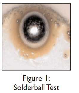
3) Solderball Test
a) The solder paste was received and
was left on the receiving dock over a
hot weekend. Is it bad? The solder
paste was left out on the manufacturing
floor for an unknown time. Is
it good? One of the best performance-
related tests to judge the usability
of solder paste is a modified
solder ball test. This test is very simple
and reveals a lot of information
about the condition of the solder
paste. Dispense a small dot of solder
paste onto an unsolderable substrate then reflow. Unsolderable
substrates are ceramic, glass, and FR-4. The solder paste deposit
after reflow should form a large ball of solder with a pool of
flux. This indicates that the flux is active enough to effectively
remove the surface oxidization of the solder powder and allow
the solder to reflow and coalesce to form a single ball. If moisture
is trapped within, or the solder paste was improperly
stored and handed, the solder may form a ball with numerous
smaller balls at a fraction of the size in the pool of flux. This
indicates that if the solder paste is used for assembly then defects
are eminent. (See Figure 1.)

4) Profile
a) Profiling is not the most exciting
task in electronics assembly,
but it does assist in
reducing potential defects. All
reflow profiles consist of a
reheat zone, soak zone, reflow
zone, and cool-down
zone. Each of these zones
are important for a successful
solder joint to be
formed. Manipulation of any
of these zones will alter the
integrity and appearance of
a solder joint.
b) The preheat zone is defined
at the lower end by the
ambient temperature, and the upper end by approximately
140-150ºC. The main purpose of this is to drive off the solvent
carrier from the solder paste deposit. The ramp rate is fairly
quick and should not exceed the component manufacturer recommendations
of 2.5-3.0ºC/sec. If
the ramp rate is greater, the components
may be thermally shocked,
warpage of the board may be induced,
and the solder paste could
slump. As the preheat zone ends, the
soak zone begins. The soak zone is
commonly bounded by 150ºC and
the liquidus temperature of the alloy,
for Sn63Pb37 the liquidus temperature
is 183ºC. The soak zone
Figure 1: has two main functions. The first is
Solderball Test
As the industry continues to move away from through-hole
technology, surface mount technology (SMT) has become
the most popular mass-assembly technique in electronics.
SMT offers new challenges and adventures for engineers to
conquer. The industry has made available numerous
resources to successful soldering for SMT. Consider these
suggestions for overcoming obstacles.


Preferred
example
24 SEPTEMBER 2000 I N S I D E L I N E
to thermally equalize
the assembly, and the
second is to activate
the flux. Activating the
flux essentially allows
the paste flux to
“chemically scrub” the
surface oxidation of
the surface finishes on
the printed circuit
board and the component leads as well as the solder powder
to promote wetting. This is accomplished within approximately
60-90 seconds. Next is the reflow zone. The reflow zone is commonly
characterized when the solder powder changes phases
from a solid to a liquid (also known as the time above the liquidus
temperature of the alloy). The peak temperature is
around 30-40ºC above the alloy liquidus temperature. The main
purpose of the reflow zone is to form a metallurgical http://improvehearingnaturally.com bond between
the component leads, solder, and the lands on the printed
circuit board. Excessive time within the reflow zone may lead
to dark, dull, grainy joints. Insufficient time within the reflow
zone may result in weak interconnects. Last is the cool-down
zone. The cool-down zone begins as the alloy solidifies. The temperature
of the assembly should not decrease too rapidly; this
may lead to thermal shock of the components. Again, follow the
component manufacturer’s recommendations.


5) Compatibility
a) Do not try to mix and match flux chemistries. Use all No Clean
products or all water-soluble products.Water-soluble flux
chemistries are very active by nature in comparison to No
Clean formulations. Due to this inherent difference, operators
may be drawn to water-soluble flux products. No Clean flux
chemistries are designed to have residues that are non-conductive
and non-corrosive, whereas water-soluble flux chemistries
are conductive and corrosive. If a water-soluble flux was used
on a No Clean assembly, this would be an important reliability
issue for the assembly and should be immediately addressed.
Any residue resulting from the use of water-soluble fluxes should
be completely removed from the assembly.

6) Printing Suggestions
a) Printing is the first process in surface mount assembling. Some
general printing suggestions are offered to reduce defects and
optimize yields. The bead diameter of the solder paste should
be approximately the same size in diameter as a cigar (about
0.5” in diameter).When the squeegee is gliding across the stencil,
the solder paste in front of the squeegee should be rolling.
This will assist in proper filling and leveling of the apertures
with solder paste in addition to achieving consistent solder
paste deposits. Traditional solder pastes required kneading to establish
a good roll, while current formulations do not possess
this attribute. Clogging of the apertures is another problem
within the printing process that is a common root cause for
many defects. Innovative solder paste formulas release cleanly
from the wall of the stencil apertures. Solder paste adhering
and drying in the apertures reduces the quantity of paste
transferred or deposited, resulting in a higher occurrence of defects
in the form of insufficients or opens.

7) Avoid Humidity and high
temperature situations
a) Solder paste can be a delicate blend of numerous chemicals to
yield a specific rheology and consistency. Harsh environmental
fluctuations will alter physical properties such as viscosity and
tack.When the humidity begins to climb above 60-70%RH, the
solder paste may entrap or absorb moisture, which will decrease
the tack and promote solderballing. A common indication will
be the solder paste sticking to the squeegee and forming a curtain
instead of releasing from the squeegee. On the other hand,
if the humidity is below 25-35%RH, then the solder paste will
dry out quickly and the stencil life will decrease, resulting in additional
scrap. If the solder paste dries out, the apertures in the
stencil are easily clogged as well. Activity, tack, and viscosity are
all properties of solder paste that are altered as the environmental
conditions go to extremes, and the inclination is to add
something to the solder paste to revive the material. This is
strongly discouraged. Solder paste does not react in the same
fashion and is unpredictable with additions. If the manufacturing
facility is prone to these harsh conditions, then make sure the
solder paste selected is robust; review Tip #1. Recent solder
paste formulations are designed to be environment-resilient.
8) Double Sided Reflow Applications
a) As the electronics industry is driven by end products that are
lighter in weight, faster, and less expensive, double-sided reflow
applications are increasing. This application can be simplified
with some useful tips. One common tip is to bias the topside
preheaters of the reflow oven slightly hotter than the bottomside
preheaters. This will direct more of the heat to the topside
of the assembly than the bottomside.When attempting this, the
temperature gradient should not exceed more than 15-20ºC, in
case the oven isn’t able to stabilize. If this tip is used, the same
alloy can be used for both sides of the assembly.While reflowing
the second side of the assembly, you may need to glue
components so they do not fall off the assembly.
9) Troubleshooting
a) As experience with a specific process increases, the defects will
be reduced and an expert will emerge. There are many ways of
finding the root cause of a defect or failure. List the possibilities
and eventually isolate the problem. Employ organized troubleshooting
techniques to quickly resolve the problem. Involve
other departments to facilitate the troubleshooting process. Engineering
and troubleshooting are typically well accomplished with
well-functioning teams.
10)Assistance
a) Do not be afraid to ask for assistance. There are several
sources for troubleshooting, problem solving, and general
question forums available. The electronics assembly community
is a helpful, very informative bunch. Solder vendors have
technical service engineers that are available to answer questions.
Another very good source is forums. The Internet-based
forums through Surface Mount Technology Association (SMTA)
and the Institute for Interconnecting and Packaging Electronic
Circuits (IPC) consist of industry professionals and consultants
that are eager to share experience.