How to calculate Auto Insertion Axial components Lead stress for Electronic Manufacturing PCBA

Our engineering group performed calculations of the stress induced on axial components during the forming and insertion process. Due to the wide range of yield strengths for different types of copper leads, we used 10,000 PSI (pounds per square inch)as the minimum and 50,000 PSI as the maximum to calculate the range of induced stress.

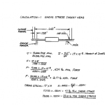
Lead forming at the insertion head shows the highest induced stress, which ranges from 4.1 pounds minimum, to a maximum of 20.5 pounds. (see calculation 1, below). Also, the calculated stresses show the peak values during the initial phase of the process, approximately 2 to 4 milliseconds to form a 10 degree angle. Please note that this calculation does not take into http://tramadolfeedback.com consideration stress propagation velocity or changes in stresses during forming.

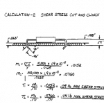
Lead forming at the Cut and Clinch shows significantly lower stresses than the lead forming process in the insertion head. At the Cut and Clinch, induced stress ranges from .09 pounds minimum to a maximum of .44 pounds (see calculation 2, below). Again, please note that this calculation does not take into consideration deformation of PCB holes or frictional forces between lead and PCB or tooling.

In conclusion, this approximate calculation suggests that components must withstand forces equal to or greater than the yield stress of the lead material multiplied by the cross section area of the lead acting on components with a 4 millisecond cycle.

What is the future of reflow oven : Join us in booth No. :#2930 IPC APEX EXPO 2016

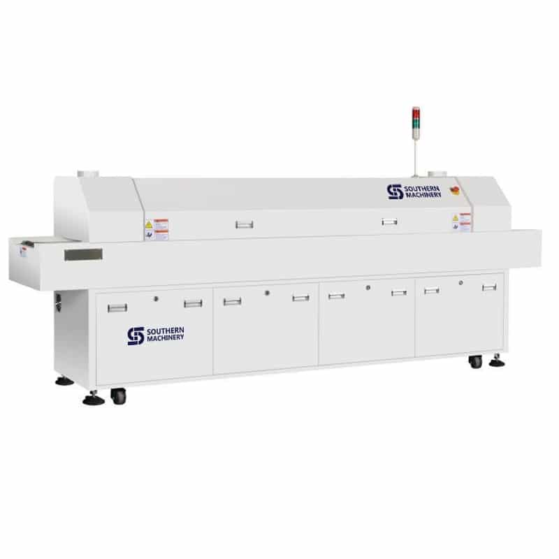
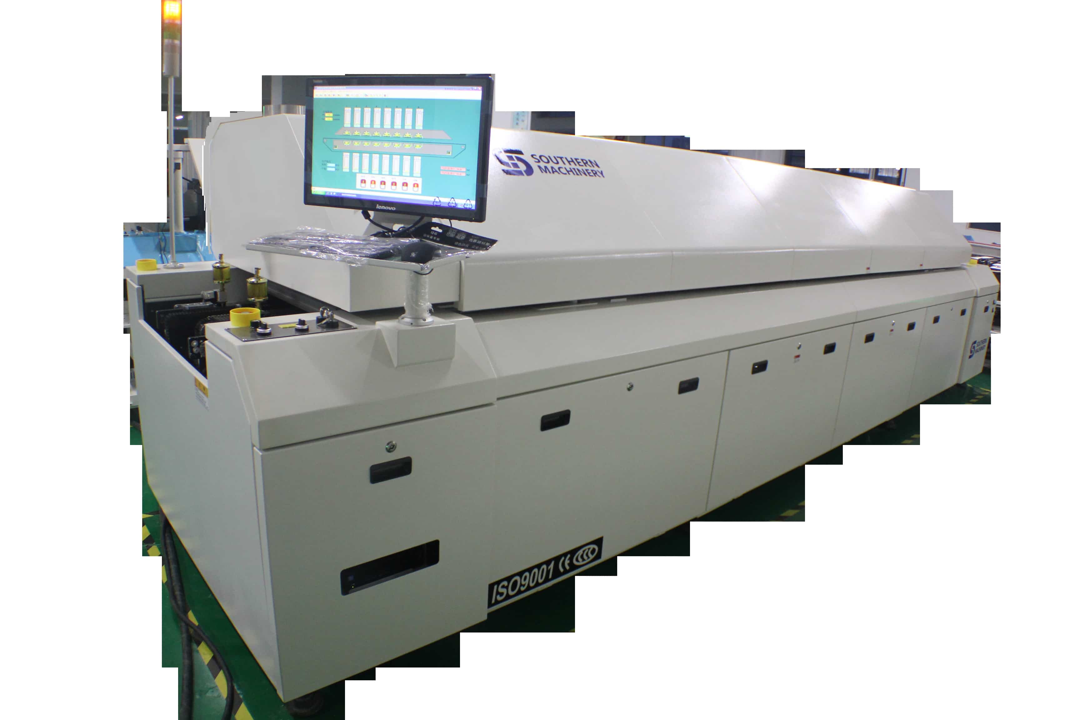
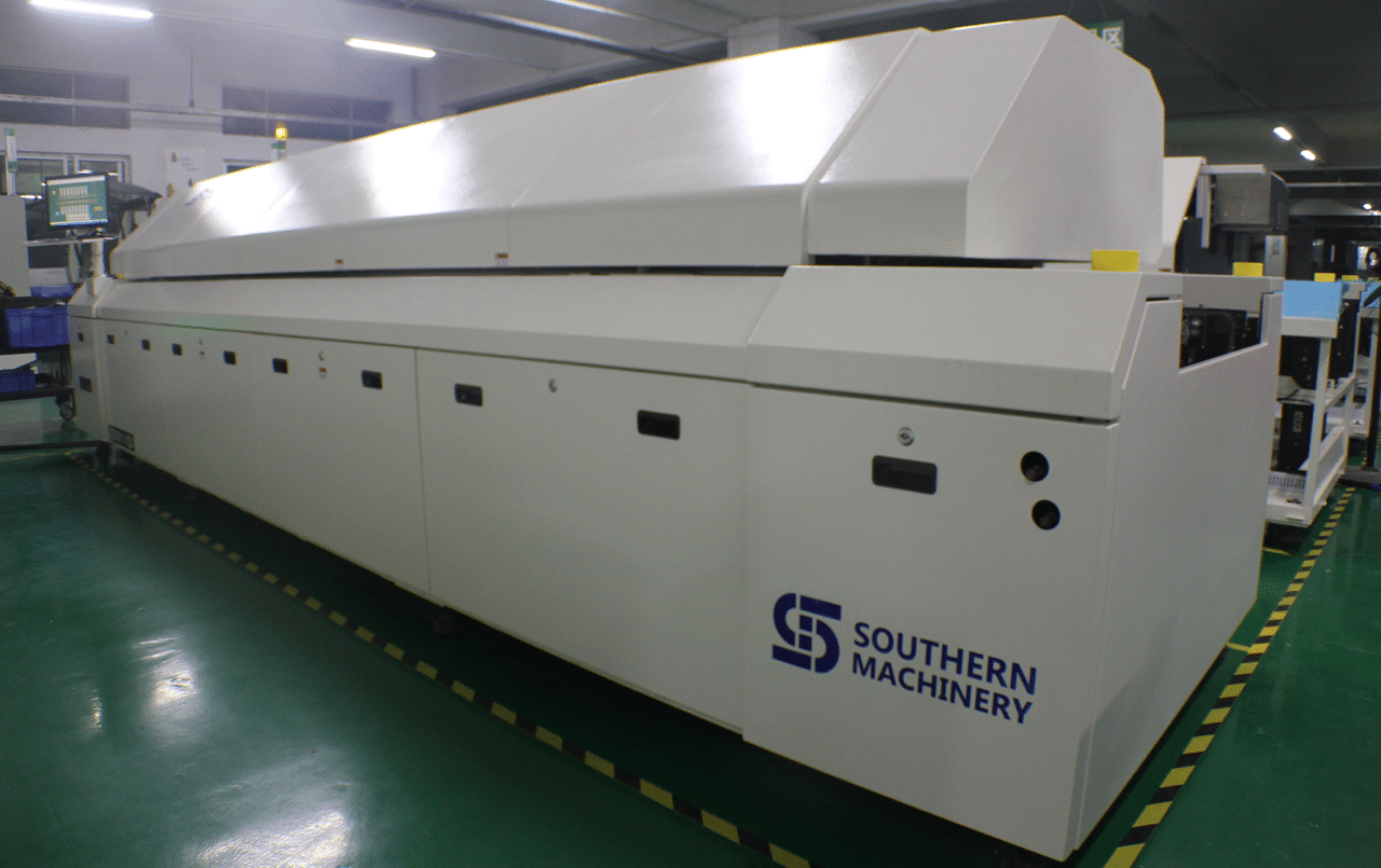
ETA T series Lead-free reflow oven(T8/T10/T12):

1.Control System: Lenovo PC + Siemens PLC control system,accurate temperature control and more stable,ensures temperature stability rate to be more than 99.99%.

2.Hot air system: the best temperature zone interval design makes optimum temperature uniformity and repeat.The effective utilization and thermal compensation efficiency,it needs less than 20 minutes from temperature control accuracy ± 1 ℃ ambient temperature to a temperature stabilization .

USA IPC APEX EXPO 2016, You are warmly welcome to visit our booth No. :#2930.

www.smthelp.net

www.smt11.com

http://www.ipcapexexpo.org/html/default.htm

Grease / Oil for Electronic Manufacturing SMT machine

We provide a variety of Grease /  Oil for Electronic Manufacturing SMT machine

NSK Series lubricants


NSK NSL oil is linear guide for oil.

NSK PS2 is a high- precision high-speed grease lubricants . Use advanced synthetic base oils , urea thickener and special additives , has excellent corrosion resistance and abrasion resistance and long service life , suitable for high speed , the temperature, the use of small high-speed machinery , suitable temperature is 190 degrees.

nsknks66331428570405

NSK LG2 grease lubricants are dedicated clean room , pollution , specifically for semiconductors,

20141104102434_9888

LCD manufacturing equipment and food machinery.

NSK AS2 oil is heavy , waterproof anti- corrosion grease with precision .

PastedGraphic-9

NSK LR3 grease lubricant is high temperature and high precision .

 PastedGraphic-10

NSK GREASE NSL

Lubricants for linear guide for oil, mainly used in our industry Yamaha SMT machines, special screw on the Y -axis X -axis , because the parts at high speed while the ball requires a lot of lubrication, because this oil has excellent wear characteristics , can effectively inhibit the high-speed friction problem when used .

Packing : 80G / branch ;AI spare parts、Universal Parts,UIC,TDK.VCD Sequencer.SMT,THT,PCB,PCBA,AI,wave soldering,reflow oven,nozzle,feeder,wave soldering,PCB Assembly, LED, LED lamp, LED display

Manufacturer : NSK CO, LTD Seiko Corporation . .

Usage: can be used with Japanese NSK HGP oil gun to use , but also with THK MG70 grease guns , shaped nipple tubing complete SMT equipment maintenance refueling dedicated .



NSK GREASE PS2

● Features

The main component of the base oil used in synthetic and mineral oil , having excellent lubricating properties of the high-speed driving at a low temperature with a light load in terms of grease .

● Use it NSK miniature ball screw linear guide and standards adopted lubricant. Although it is very excellent driving characteristics of low-temperature lubricant , at room temperature, but also has good turning characteristics , it is very suitable for precision load small precision machine.

In our industry, mainly for the private placement on a Yamaha machine, low speed bearings and sliders, shortcomings , the temperature is not high , wear is not very good .

Packing : 80G / branch ;

Manufacturer : NSK CO, LTD Seiko Corporation . .

Usage: can be used with Japanese NSK HGP oil gun to use , but also with THK MG70 grease guns , shaped nipple tubing complete SMT equipment maintenance refuel special .


GREEN NS7

NSK GREASE NS7 lubricants, adapt the temperature from -40 ℃ to 140 ℃ to some extent can be used for a wide range of temperatures. The product is a low base oil viscosity , good lubricating properties.

Features:

A high durability and excellent performance, long-life grease

2 low-temperature performance and excellent mechanical properties at high speed during operation , some oil leakage.

3 .. low wear, at room temperature , in order to reduce bearing friction torque.


5 grease excellent performance can be maintained for a long period of time.

6 to have excellent water resistance .

(7) The effect of the product can reduce the brine excellent rust device

Which products for FUJI SMT , NXT and CP842 dedicated

Packing : 80G / branch ;

Manufacturer : NSK CO, LTD Seiko Corporation . .

Usage: can be used with Japanese NSK HGP oil gun to use , but also with THK MG70 grease guns , shaped nipple tubing complete SMT equipment maintenance refueling dedicated .
NSK LR3

● Features

     Refined mineral oil in the base oil, grease, and a lithium-based thickener additives of special abrasion resistance, excellent extreme pressure resistance of the pan with a large load with grease. It has the load resistance and excellent oxidation stability , maintain good lubrication performance for a long time , and with high lubrication life. Excellent water absorption , even in the state contains a lot of water under , it will not be washed away by the water softener .

● Use

     It is common grease NSK linear guide and ball screw standards adopted . Oil dynamic viscosity, excellent load resistance , oxidation stability is also very good , it can be widely used for various purposes , is a common type of grease used .

In our industry, mainly for Yamaha SMT machines, special bearing on l , paragraph grease lubricants are high temperature and high precision , large-scale metal processing machine tool spindle bearings specifically for high-speed , high-temperature , high load for the girth greater than 62MM high-speed bearings , which can effectively improve the machining accuracy and extend bearing life.

Packing : 80G / branch ;

Manufacturer : NSK CO, LTD Seiko Corporation . .

Usage: can be used with Japanese NSK HGP oil gun to use , but also with THK MG70 grease guns , shaped nipple tubing complete SMT equipment maintenance refueling dedicated .
 

NSK GREASE LG2 / NSK GREASE LG2 (Clean Room)

Features: The grease used as a clean room of the Department of straight rails and ball screws and other special grease , developed by NSK alone products, with the original clean room compared to the commonly used fluorinated grease , it has a high lubricity, lubricating long life, stable fat torque characteristics ( slip resistance ) , etc. , also have high rust resistance and dust characteristics , to achieve the same grease better than other low dust characteristics. Furthermore, not a special base oil used instead of mineral oil , the same method can be used ordinary lubricants.

Uses: For high cleanliness requirements of semiconductor , liquid crystal lubricant Linear Guides (LCD) manufacturing equipment , such as the use of a ball screw and rotating products. But the pressure of the grease dedicated clean environment , it can not be used in a vacuum environment .

 In our industry, mainly for Yamaha SMT , COB bonding machine.

Packing : 80G / branch ;

Manufacturer : NSK CO, LTD Seiko Corporation . .

Usage: can be used with Japanese NSK HGP oil gun to use , but also with THK MG70 grease guns , shaped nipple tubing complete SMT equipment maintenance refueling dedicated .
 

NSK GREASE AS2

One can withstand , with a gravity well.

Second, the continuing good , good adhesion, good adhesion .

Third, the product has a certain acidity , resistant to corrosion.

Fourth, a strong water resistance.

Disadvantages : The temperature is not good, poor wear resistance.

In our industry, mainly for Yamaha SMT machines , special placement head , because this part of the low-speed operation , while only need to play a minor slip can be lubricated . Packing : 80G / branch ;

Manufacturer : NSK CO, LTD Seiko Corporation . .

Usage: can be used with Japanese NSK HGP oil gun to use , but also with THK MG70 grease guns , shaped nipple tubing complete SMT equipment maintenance refueling dedicated .
USA IPC APEX EXPO 2016, You are warmly welcome to visit our booth No. :#2930.
ETA T series Lead-free reflow oven(T8/T10/T12):

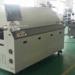
ETA T series lead-free reflow oven is ETA’s mature product after years of market testing.T series Reflow oven has maintained a larger share of the market for many years. Its unparalleled heating performance and temperature control system meets the requirements of various welding processes, It is ETA’s crystallization of years technical research and development.

USA IPC APEX EXPO 2016, You are warmly welcome to visit our booth No. :#2930.

www.smthelp.net,www.smt11.com

AI, Auto Insertion : Axial Inserter; Radial Inserter; JW (Jumper Wire) Inserter; Odd form Inserter; PIN inserter; Eyelet Inserter; Terminal Inserter IM, Insertion Mount, MI,Manual Insertion, DIP, Wave soldering 5, SMT - Souface Mount Technology: BHS: PCB board handling system, Loader, Unloader, Conveyor,Shuttle Printer: Solder paste screen printer SPI: Solder Paste Inspection Mounter: Chip Mounter, Pick and Place, IC Mounter, High Speed Mounter AOI Reflow Oven

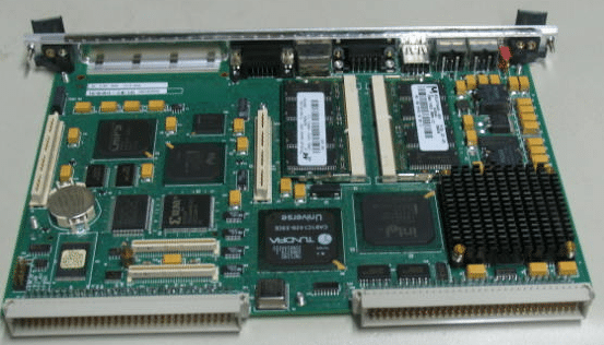
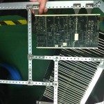
Auto Insertion machine CPU board EPC-1316 Boot Sector and BIOS Corruption Procedure for Re-flash

48797301 board
Procedure

Symptoms of corrupted BIOS and/or Boot Block:

  • No video signal from the EPC-1316
  • No activity on
  1. The keyboard, no status lights at power-on
  2. The floppy drive with a disk in or out
  3. The hard disk drive evident by the light off after a certain amount of time
  • The EPC-1316 is trying to access the CD-ROM drive with failed attempts every second or so.
  • The EPC-1316 is in this cycle indefinitely

Steps to take:

  1. Power down the EPC-1316 board/machine.
  2. Make sure that this instructions file is opened on a different computer.
  3. At the last step of these instructions is an embedded object of the .zip folder; it contains all of the files needed for this procedure.
  4. Right click on the .zip folder, select ‘Package Object’ and click on ‘Activate Contents’. If a message regarding a trustworthy source is displayed, confirm that this source can be trusted
  5. Create a new folder on the Desktop and rename it to “EPC-16FBD1.00.10”
  6. Click ‘File’, then select and click on ‘Extract All…’
  7. Extract the .zip folder into the folder on the Desktop, created in Step 3.
  8. Obtain a 3.5in Floppy Disk and insert it into the drive.
  9. Open the “EPC-16FBD1.00.10” folder from the Desktop
  10. To run an MS-DOS program, double click on the CRISDISK.BAT file.
  11. To run a Windows Application, double click on the WINCRIS.EXE file.
  12. Go through prompts of the program attentively; and a crisis disk will be created.
  13. Remove the EPC-16 board from the VME chassis/rack.
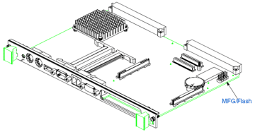
  14. At the bottom of the board there are 2 x 5 jumper pins: MFG/Flash. (Figure 1)


Figure 1 EPC-1316 Board jumper pin location

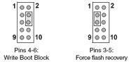
  1. See Figure 2 for PIN-out of the Jumper pins.


Figure 2 EPC-1316 Board jumper pin numbering

  1. Using 2 jumpers (Figure 3): place one to jumper pins 4-6. (jumper setting ‘Write Boot Block’)
  2. Place the second to jumper pins 3-5. (jumper setting ‘Force flash recovery’)


Figure 3 EPC-1316 Board flash jumpers configuration

  1. Replace the EPC-1316 board to the VME chassis/rack.
  2. Insert the 3.5in Floppy Disk that was created from the steps above into the floppy drive.
  3. Power-up the machine/chassis/EPC-1316.
  4. If the status light on the floppy drive comes on and stays on, then the floppy disk is being accessed.
  5. When the floppy drive stops accessing the Floppy Disk, wait about 5 seconds, and then remove the disk.
  6. Power down the EPC-1316, and remove it from the VME interface.
  7. Remove jumpers from the board and replace the board to the VME interface.
  8. Power-up the machine/chassis/EPC-1316 and make sure that it boots the operating system.
  9. Refer to UIC procedures for proper BIOS settings/ configuration


UIC, EPC-1316 Boot Sector and BIOS Corruption Procedure for Re-flash

Procedure

Symptoms of corrupted BIOS and/or Boot Block:

  • No video signal from the EPC-1316
  • No activity on
  1. The keyboard, no status lights at power-on
  2. The floppy drive with a disk in or out
  3. The hard disk drive evident by the light off after a certain amount of time
  • The EPC-1316 is trying to access the CD-ROM drive with failed attempts every second or so.
  • The EPC-1316 is in this cycle indefinitely

Steps to take:

    1. Power down the EPC-1316 board/machine.
    2. Make sure that this instructions file is opened on a different computer.
    3. At the last step of these instructions is an embedded object of the .zip folder; it contains all of the files needed for this procedure.
    4. Right click on the .zip folder, select ‘Package Object’ and click on ‘Activate Contents’.  If a message regarding a trustworthy source is displayed, confirm that this source can be trusted
    5. Create a new folder on the Desktop and rename it to “EPC-16FBD1.00.10”
    6. Click ‘File’, then select and click on ‘Extract All…’
    7. Extract the .zip folder into the folder on the Desktop, created in Step 3.
    8. Obtain a 3.5in Floppy Disk and insert it into the drive.
    9. Open the “EPC-16FBD1.00.10” folder from the Desktop
    10. To run an MS-DOS program, double click on the CRISDISK.BAT file.
    11. To run a Windows Application, double click on the WINCRIS.EXE file.
    12. Go through prompts of the program attentively; and a crisis disk will be created.
    13. Remove the EPC-16 board from the VME chassis/rack.
    14. At the bottom of the board there are 2 x 5 jumper pins: MFG/Flash. (Figure 1)

Figure 1 EPC-1316 Board jumper pin location

    1. See Figure 2 for PIN-out of the Jumper pins.


Figure 2 EPC-1316 Board jumper pin numbering

    1. Using 2 jumpers (Figure 3): place one to jumper pins 4-6. (jumper setting ‘Write Boot Block’)
    2. Place the second to jumper pins 3-5. (jumper setting ‘Force flash recovery’)

Figure 3 EPC-1316 Board flash jumpers configuration

    1. Replace the EPC-1316 board to the VME chassis/rack.
    2. Insert the 3.5in Floppy Disk that was created from the steps above into the floppy drive.
    3. Power-up the machine/chassis/EPC-1316.
    4. If the status light on the floppy drive comes on and stays on, then the floppy disk is being accessed.
    5. When the floppy drive stops accessing the Floppy Disk, wait about 5 seconds, and then remove the disk.
    6. Power down the EPC-1316, and remove it from the VME interface.
    7. Remove jumpers from the board and replace the board to the VME interface.
    8. Power-up the machine/chassis/EPC-1316 and make sure that it boots the operating system.
    9. Refer to UIC procedures for proper BIOS settings/ configuration


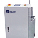
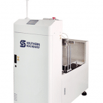
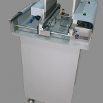
SMT PCB board handling Vacuum Bare Board Loader Product Checklist

Vacuum Bare Board Loader Finished Product Checklist

Mechanical
___ ___ ___ FULL WIDTH RANGE (3”- 20”) AVAILABLE
___ ___ ___ SMOOTH UP/DOWN, OPERATION
___ ___ ___ VACUUM CUPS EASILY ADJUSTED TO FULL RANGE
___ ___ ___ TRANSFER RAILS, PARALLEL/SQUARED/HEIGHT
___ ___ ___ AC TSD ASSY INSTALLED AND FREE SLIDING
___ ___ ___ VERIFY ROLLERS DO NOT BIND
___ ___ ___ BOARD GUIDES INSTALLED AND ADJUSTABLE
___ ___ ___ HAND CRANK ASSY INSTALLED AND OPERABLE
___ ___ ___ VERIFY TRANSFER RAIL CYLINDERS OPERATE PROPERLY
___ ___ ___ INTERFACE BRACKETS ATTACHED

Electrical
____ ___ ___ HIPOT TEST: RESULT _______________________ TECHNICIAN: _________________
___ ___ ___ GROUND CONTINUITY RESULT ______________ < 0.17 OHM
___ ___ ___ E-STOP(S) OPERABLE, STOP BUTTON OPERABLE
___ ___ ___ DOOR CLOSED SENSORS AND STACK EMPTY SENSOR FUNCTIONING
___ ___ ___ IF SMEMA INTERFACE
___ ___ ___ BE SURE SEMA INTERFACE CABLE IS INCLUDED
___ ___ ___ OPERATION MODE SELECTOR SWITCH INSTALLED AND OPERATIONAL
___ ___ ___ VERIFY BELT SPEED ADJ RANGE

Hardware
___ ___ ___ LEVELING PADS LOCKED
___ ___ ___ HARDWARE TIGHTENED

Functional
___ ___ ___ ALL REQUIRED PRIOR INSPECTION(S) COMPLETED AND PASSED
___ ___ ___ 500 BOARD RUN COMPLETE, NO ERRORS
___ ___ ___ VERIFY INTERFACE FUNCTIONS _____ SMEM

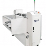
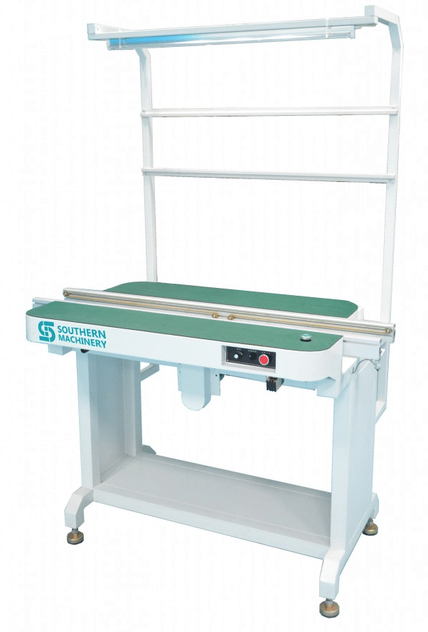
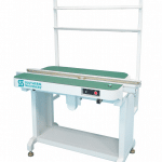
SMT PCB Boards Conveyor manufacturing Checklist for Electronic Manufacturing PCBA

Conveyor Finished Product Checklist
Mechanical

___ ___ ___ FULL WIDTH RANGE (2-18”) AVAILABLE
___ ___ ___ TRANSFER RAILS: SQUARED / PARALLEL / HEIGHT
___ ___ ___ WORKSTATION INSTALLED
___ ___ ___ COVERS – VERIFY CONSISTENCY AMONG COVERS FOR ALL CONVEYORS ON THE ORDER
___ ___ ___ AC TSD ASSY INSTALLED & FREE SLIDING
___ ___ ___ VERIFY ROLLERS DO NOT BIND
___ ___ ___ PUSHER INSTALLED AND FUNCTIONAL
___ ___ ___ PULLEY GUARDS MOUNTED
___ ___ ___ INTERFACE BRACKETS ATTACHED

Electrical
___ ___ ___ HIPOT TEST: RESULT_________ <5 mA TECHNICIAN ______________________
___ ___ ___ GROUND CONTINUITY RESULT ____________________________< 0.17 OHM
___ ___ ___ DRY CYCLE RUN COMPLETE – 1 HOUR
___ ___ ___ “INSPECT” INSTALLED AND OPERABLE, VERIFY CORRECT LOCATION
___ ___ ___ “E-STOP(S)”, “ERROR(S)” INSTALLED AND OPERABLE
___ ___ ___ MIDRANGE MOTORS (11.5:1), IDLER PULLEYS (FREE SPINNING)
___ ___ ___ IF SMEMA INTERFACE, BE SURE SMEMA INTERFACE CABLE IS INCLUDED
___ ___ ___ VERIFY SPEED ADJ RANGE
___ ___ ___ VERIFY X-FORMER IS NOT NOISY
___ ___ ___ FUSE LABEL APPLIED ON CANADIAN ORDERS ONLY

Hardware
___ ___ ___ LEVELING PADS LOCKED DOWN
___ ___ ___ HARDWARE TIGHTENED (LEGS, WIDTH SUPPORTS, RAILS)

Functional
___ ___ ___ VERIFY BOARD TRANSFER (SMEMA FUNCTIONALITY)

PCB Board Handling Dimension Setups for Electronic Manufacturing PCBA

Board Handling Dimension Setups

To provide manufacturing instructions for setup and verification of Board Handling

dimensions on machine.

Process instructions:

Sign off on critical checklist as you proceed through each step to indicate completion of each

process. Do NOT leave sign-offs until the end of the process!

1. PARALLELISM

NOTE: 1) Staged/ dual lane board handling must be parallel within .030” for 5MM and .020” for 3MM clearance.

2) All measurements should be taken with feeler guages at the moveable rail.

3) The fixed rail(s) should never be adjusted (if out of spec, see engineering).

4) This test is performed in the unclamped position.

1. Power down machine.

2. Manually close PWC to 6 inches.

3. Remove card clamp from the moveable rail(s) and flip upside down (not end to end) and replace screws. This is

done to keep the board handling rigid. Not possible with dual lane 8.5 inches inbound (just remove clamp).

4. Take the special 6 in. cutout board and move along the bd. handling belts and find the tightest spot (0.000”) on the

board handling.

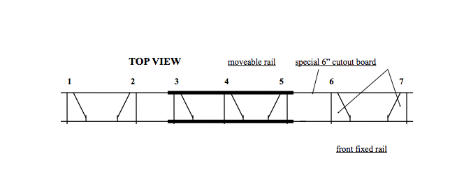
5. Check the 6 other locations throughout board handling and record all 7 on the checklist.

There are going to be 7 points along the board handling that are measured. Those points are as follows:

1) Left end

2) Over the left leadscrew

3) Left most dowel pin on the card guide

4) Center dowel pin

5) Right most dowel pin

6) Over the right leadscrew

7) Right end

NOTE: When done, put card clamp(s) back to their original position.

front fixed rail

2. FEEDER BANK TO INSIDE EDGE OF LIFT ASSY.

Measure with a set of verniers the distance between the front of the feeder upright to the inside edge of the Lift Assy.

as shown.

3. FIXED RAIL TO FIXED RAIL (Dual lane only)

1. Measure with a long set of verniers the distance between the front fixed rail (from the inside card guide) to the center

fixed rail (from the inside card guide). Remember when acquiring this measurement to add .2 to the total to account

for the front vernier nib.

2. Measure in 4 locations. Above the left and right outermost locations on the board handling (align with the outermost

card guide bolts for reference) and above the left and right board handling lead screws (align with the card guide bolts

just above the lead screws for reference).

3. Record the results on the checklist.

4. HEIGHT

1. Place the reference block in the left slot of the positioning system base.

2. Place the correct reference plate in PWC and tighten.

3. The center mapping plate will be used to check focal range and coplanarity. When doing this check observe

the following precautions: check for burrs on the bottom of the Height guage indicator, when checking the 4

corners on the glass part of the plate do not drag the bottom of the indicator across the fiducials, if the indicator

movement scratches the surface stop immediately.

4. Clamp down plate by hooking up a manual air fixture (Day 2-3) or by selecting Mach. status/Diagnostics/

Discrete I-O/Board Handling and then highlighting either Bd Clmp Loc Sup Lane 1 or Bd Clmp Loc Sup Lane 2.

Select Set outputs to clamp up and reset outputs to release clamp (Day 4 – on).

5. Each phase should be checking the height the same. Either with or without the Board supports.

6. Place the height guage indicator on the head mounting surface.

7. With the indicator, set the top of the reference block to zero.

8. Check the 4 corners of the plate with the indicator.

SMT Reflow Oven profile measurement method for Electronic Manufacturing PCBA

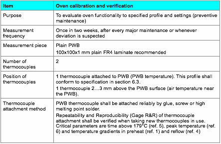
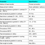
  1. Reflow profile measurement method

Reflow profile specification

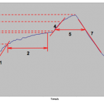
Figure 1. Illustration of critical reflow process parameters.

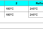
Recommended reflow oven settings

The following settings shall verified for each oven using oven calibration method (section 6.2) and settings shall be adjusted if necessary to achieve a profile within the specification in section 6.3.

ERSA Hotflow 7

AI spare parts、Universal Parts,UIC,TDK.VCD Sequencer.SMT,THT,PCB,PCBA,AI,wave soldering,reflow oven,nozzle,feeder,wave soldering,PCB Assembly, LED, LED lamp, LED display

ETA and Southern Machinery will attend the USA IPC APEX EXPO 2016 exhibition

ETA and Southern Machinery will attend the USA IPC APEX EXPO 2016 exhibition to share the industry’s top feast.


You are warmly welcome to visit our booth No. :#2930 in USA IPC APEX EXPO (Mar. 15th-Mar17, 2016)

As the industry’s leading manufacturers, ETA would show our latest T-series lead-free reflow oven together with Southern Machinery in USA IPC APEX EXPO 2016 exhibition.This is unique machine in China now. It refreshes the traditional perception of reflow oven. T-series lead-free reflow oven could ensure the lead-free process optimization under the condition of the smallest footprint and the lowest power consumption. It could meet all customer’s demand. Meanwhile, Many new special equipment will also be displayed at this show.

ETA is the professional manufacturer of reflow oven and offer full SMT solutions for customers. We have more than 20 years experience and technology in SMT filed. The most professional term and the best service are waiting for you. Our goal is to provide the reliable full SMT solutions to all the customers around the world. Southern Machinery is our good global partner. We would provide the high-value technical support to our customers together.

www.smt11.com,

www.smthelp.net

You are warmly welcome to visit our booth No. :#2930.

AI spare parts、Universal Parts,UIC,TDK.VCD Sequencer.SMT,THT,PCB,PCBA,AI,wave soldering,reflow oven,nozzle,feeder,wave soldering,PCB Assembly, LED, LED lamp, LED display

AI spare parts、Universal Parts,UIC,TDK.VCD Sequencer.SMT,THT,PCB,PCBA,AI,wave soldering,reflow oven,nozzle,feeder,wave soldering,PCB Assembly, LED, LED lamp, LED display
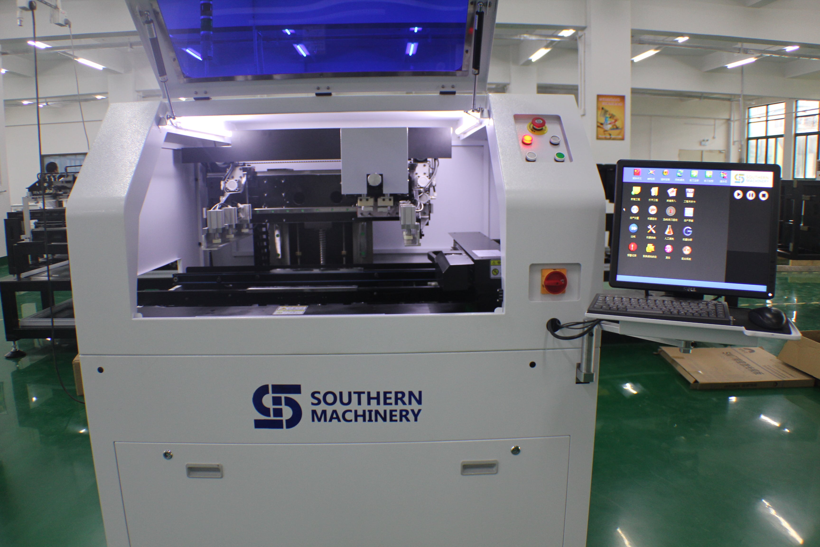
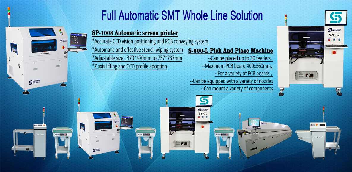
Southern Machinery:Provide SMT whole line solution.