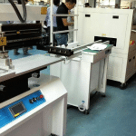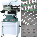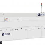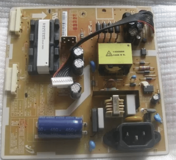
Next PCBA: welcome to IPC APEX 2016 booth No. :#2930.

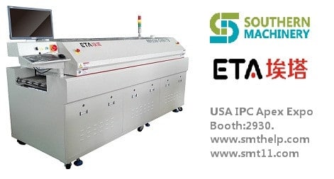
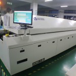
ETA T series Lead-free reflow oven(T8/T10/T12):
1.Hedging: Import hardware configuration,low failure rate in production,more than a decade service life.
2.Safety: Based on the general rules of international design, close to imported reflow rating, the highest security level.
3.Stable: mature software, hardware and top production processes ensures stability of each equipment.
USA IPC APEX EXPO 2016, You are warmly welcome to visit our booth No. :#2930.
www.smthelp.net,www.smt11.com

It is time to copy China: welcome to visit IPC APEX EXPO 2016. see you in Booth:#2930.

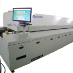
ETA T series Lead-free reflow oven(T8/T10/T12):

1.Heating module: Transverse reflow design makes temperature from each zone is not influenced by neibour to ensure accurate temperature curve, while ensuring a high production capacity and heat exchange capacity to achieve high adaptability (to meet the soldering of automotive, communications, electronics, computers and mobile phones consumer electronics.)

2.Hot air motor with independently inverter controlled, set operating frequencies depending on different technology to meet a variety of lead-free processes.

USA IPC APEX EXPO 2016, You are warmly welcome to visit our booth No. :#2930.

www.smthelp.net,www.smt11.com

Electronic Manufacturing SMT ROOM DESIGN for Reflow Oven


Electronic Manufacturing/PCB Assembly

ROOM DESIGN
OVERVIEW
Locate the reflow oven away from drafty areas such as loading
docks and air conditioning vents.
Some other considerations are:
a) Is the floor level?
b) Is the floor strong enough for the load?
c) Is the floor vibration-free?
d) Is other equipment too close?
e) Is there electromagnetic interference nearby?
f) Is electrical power, exhaust ducting, and nitrogen nearby.
g) Is the door(s) large enough to move the machine?

PLANNING THE LAYOUT
The Reflow Oven Data Tables provide information to help plan the space for reflow oven:
a) Machine clearances
b) Machine dimensions
c) Machine weights
d) Crate dimensions
e) Electrical Requirements

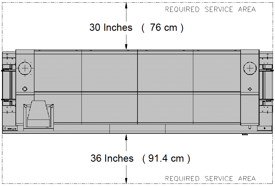
MACHINE CLEARANCES
The clearances shown in the above plan view are necessary to provide
a safe area within which to maintain the Reflow Oven.
All applicable Codes and Regulations should be considered when
providing service space.
A vertical clearance of 113 inches (287 cm) above the operating floor is
necessary to accommodate the oven with the hood and service cover
open. (This is intended to provide approximately 36 inches (91 CM)
upper clearance with the oven fully open ).

ROOM PLANNING
ACCESS
The doors and other openings should be large enough for personnel and
equipment moving and placing the machine. When the machine is being
lifted, 1″ to 6″ (2.5 CM to 15 CM) clearance is necessary above the machine
to allow for the lifting height of the moving equipment.
CEILING
The ceiling must be high enough to accommodate the machine’s maximum
height with the bonnet and service cover open, plus an allowance for the
exhaust ducts to be connected to the machine’s exhaust ports.
(See Oven Outline Drawings for dimensions)
FLOOR
The machine must be located on a concrete floor not subject to vibration
from other machinery or passing fork trucks etc. Vibration in the floor may
cause problems with the machine’s conveyors and the printed circuit boards
being processed. Only a level concrete floor treated to prevent dust should
be considered.
PLANT CONNECTIONS FOR SERVICES

Exhaust Connections
The reflow oven requires one main facility exhaust connection
branched into two sections, each connected to the exhaust vents on the
oven as illustrated in the Oven Outline Drawing. The main facility drop
should be centered above the oven as much as possible. The ducting needs
to be flexible and durable enough to allow opening and closing of both the
Hood for Service of the oven. The installation of an adjustable throttling
dampers in the exhaust connection is recommended to allow flow
adjustments as necessary.

4 BASIC FACILITY REQUIREMENTS for SMT Reflow Oven

BASIC FACILITY REQUIREMENTS
The following facility services are required at the machine area for
installation:
a) – Electrical Power
b) – Exhaust Connections
c) – Nitrogen Supply
d) – Compressed Air

SITE PREPARATION CHECKLIST
____ Electrical power provided for the machine as stated on your
company’s purchase Order ?
____ Properly rated circuit breaker or fused disconnect installed for the
oven ?
____ Nitrogen source (if N2 Oven) correctly sized, located and plumbed to
the oven location ?
____ Compressed air supply correctly sized, located and plumbed to the
oven location ?
____ Exhaust correctly sized and located?
THE WORK ENVIRONMENT
The machine will operate most effectively in a properly conditioned
environment. Excessive heat, cold, drafts, dryness, humidity, shock,
vibration or dirt may adversely http://propeciafinasteridestore.com affect the operation of the machine.
AIR CONDITIONING
The system is designed to operate within the following environmental
conditions:
Temperature: 55o – 90o F (13o – 32o. C)
Humidity: 20% – 90% NON-CONDENSING
VIBRATION
Installation should be on a vibration-free floor surface. The
recommended surface is a properly treated concrete floor with
sufficient structural rigidity to eliminate the transmission of vibration to
the machine. The floor should have the strength to support the weight
of the machine and permit proper leveling of the machine. Concrete
floors should be treated for dust prevention.
LIGHTING
The lighting level should be adequate in the work area around the
machine to allow operation, servicing and maintenance without glare
and eyestrain.

What is Calibration for SMT Pick and Place machine in electronic manufacturing

Calibration: What is Calibration?

Calibration is a process by which the location of the positioning system and vision cameras are determined in the mapped space of each machine. The ‘positioning system’ and vision cameras will be briefly described in a later section, under System Overview. Calibration process produces a large number of data that relate to the physical aspects of the machine. Typically, it produces a machine model file with data sets that:

a) locate PEC camera’s ( Position Error Correction or downward looking camera ) position , orientation as well as relate pixel values to Carriage Coordinates.

b) relate P2P (Part to Pad ) or ULC ( upward looking camera) camera pixel coordinates to machine Coordinates in microns and provide its location and orientation

c) map Theta encoder readings to spindle Theta

d) provide X, Y spindle locations when a spindle is down in Carriage Coordinates

e) indicate spindle X, Y and Theta runout , which are displacements in x, y and theta that may occur when the spindle moves up or down for part viewing and part pick / placement operations.. The spindle runout quantities need to be corrected for high precision placement of parts. A schematic diagram that explains spindle run out appears later in the document,

when the actual calculations are detailed.

What is Calibration for SMT Pick and Place machine in electronic manufacturing

Calibration: What is Calibration?

Calibration is a process by which the location of the positioning system and vision cameras are determined in the mapped space of each machine. The ‘positioning system’ and vision cameras will be briefly described in a later section, under System Overview. Calibration process produces a large number of data that relate to the physical aspects of the machine. Typically, it produces a machine model file with data sets that:

a) locate PEC camera’s ( Position Error Correction or downward looking camera ) position , orientation as well as relate pixel values to Carriage Coordinates.

b) relate P2P (Part to Pad ) or ULC ( upward looking camera) camera pixel coordinates to machine Coordinates in microns and provide its location and orientation

c) map Theta encoder readings to spindle Theta

d) provide X, Y spindle locations when a spindle is down in Carriage Coordinates

e) indicate spindle X, Y and Theta runout , which are displacements in x, y and theta that may occur when the spindle moves up or down for part viewing and part pick / placement operations.. The spindle runout quantities need to be corrected for high precision placement of parts. A schematic diagram that explains spindle run out appears later in the document,

when the actual calculations are detailed.

Tomorrow’s technology for PCBA SMT at #2930 IPC APEX EXPO 2016

Effective leaders commit to their responsibilities. They know where

they need to go and how to get there. Having earned their credentials

through exemplary performance, they use their skills and experience to

benefit those they serve.

At smthelp.net, we believe that the best way to keep our

customers at the forefront of their http://buycialisquality.com industries is to strive to remain at

the forefront of ours. We stay ahead of the technology curve and

remain responsive to business needs. So our customers are able to rely

on the most capable and dedicated service every hour of every day.

Tomorrow’s technology for PCBA SMT at #2930 IPC APEX EXPO 2016

Effective leaders commit to their responsibilities. They know where

they need to go and how to get there. Having earned their credentials

through exemplary performance, they use their skills and experience to

benefit those they serve.

At smthelp.net, we believe that the best way to keep our

customers at the forefront of their industries is to strive to remain at

the forefront of ours. We stay ahead of the technology curve and

remain responsive to business needs. So our customers are able to rely

on the most capable and dedicated service every hour of every day.

What is tomorrow electronics manufacturing — #2930 IPC APEX EXPO 2016

When you’re flying high, you need complete faith in what’s
keeping you there: that includes your technology, your expertise,
and the team that supports you.

At smthelp.net we, too, strive to deliver
perfect performance in everything we do. Our
commitment underlines all that we are: technologists,
process specialists, and a dedicated business partner able to
tailor solutions that bear the closest scrutiny and deliver exceptional results.

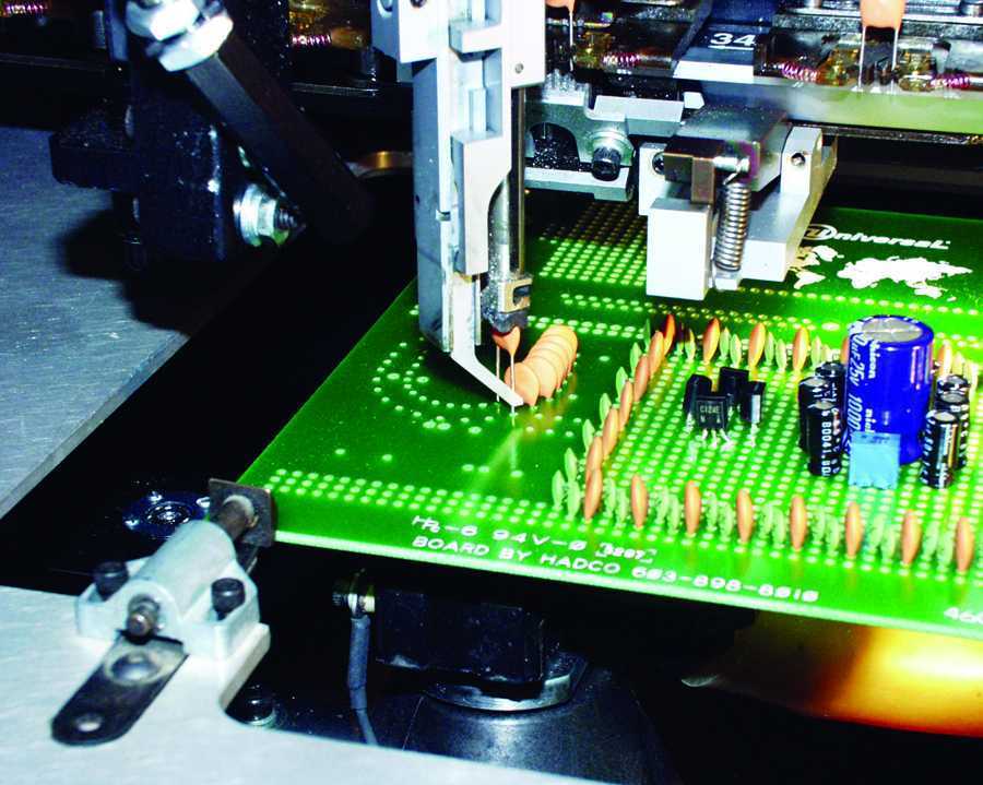
How Auto Insertion Machine Axial Component Insertion Head works for PCBA

Low Parts Count:
Once the Low Parts sensor is made (parts are not detected) the machine counts insertions for the head that is low on parts. When the count is reached the machine stops with an error code indicating it is low on parts. If the sensor detects parts before the machine stops, the counter is reset. If no Low Parts sensor is mounted, this field is not used and the default is zero.

Shuttle Off Timer:
When the shuttle is retracted to the home position, a timer is started in the software. When the time exceeds the value entered, the shuttle is allowed to fire again when the routine calls it (sets a minimum dwell time for the shuttle). One of the uses of this setting is to allow more or less time for a pin or socket to enter the escapement on a vibratory bowl fed part. For example when feeding a component lengthways in to the escapement, an excessively long time may be required. The default is 100 milliseconds and should be used for most applications.

Air Clean Timer:
Once the head down signal is made, Vacuum is turned off, the Air Clean valve is fired and the software starts a timer. When the timer expires, the Air Clean valve is turned off and Vacuum is eventually turned on again. Vacuum can be used to hold a Pin in the head during the transition to the board. The air Clean can then be used to clear the Top Die of debris before the next cycle. The default is 50 milliseconds, and should not be changed for most applications.

Head Delay:
After the anvil is fired the software sets a delay and waits for it to expire before firing the head (if the delay is zero, the head and anvil fire simultaneously. This can be used to ensure that the anvil beats the head to the board. As a rule, the anvil is usually quicker to the board http://findviagra.com than the head. The cycle time for the head and anvil can be measured using IM Diagnostics to fire the outputs and monitor the inputs. The default for Head Delay is zero milliseconds and should be used in most applications.

Part Settle Delay:
After the anvil makes the Anvil Up switch and the head makes the Head Down switch, the software sets a delay before retracting the head and anvil to their home positions. This allows the amount of time to “set” the part to be selectable. A symptom of to short a Part Settle Delay is inconsistent or loose settings of the component. The default is 20 milliseconds and should be used in most applications.

Shuttle In:
Selected if there is a Shuttle In sensor. If this is not selected, the routine will not look for Shuttle In.

Part Present:
Selected if there is a Part Present sensor. If this is not selected, the routine will not look for Part Present.

Anvil Up:
Selected if there is an Anvil Up sensor. If this is not selected, the routine will not look for Anvil Up.

Anvil Aux In:
Selected if there is an Anvil Aux sensor. This can be used as a “Clinch” option after the Anvil Up sensor is made, or as a way to fire the anvil up after the head is down. If this is not selected, the routine will not look for Anvil Aux In.

Tooling Safe:
Selected if Head Home AND Tooling Safe are required before moving the positioning system. As an example, the Cambridge terminal head needs to see both Head Home And Tooling Safe before ensuring that the table can move without damaging the head tooling. If not selected, the software only needs to see one or the other before moving.
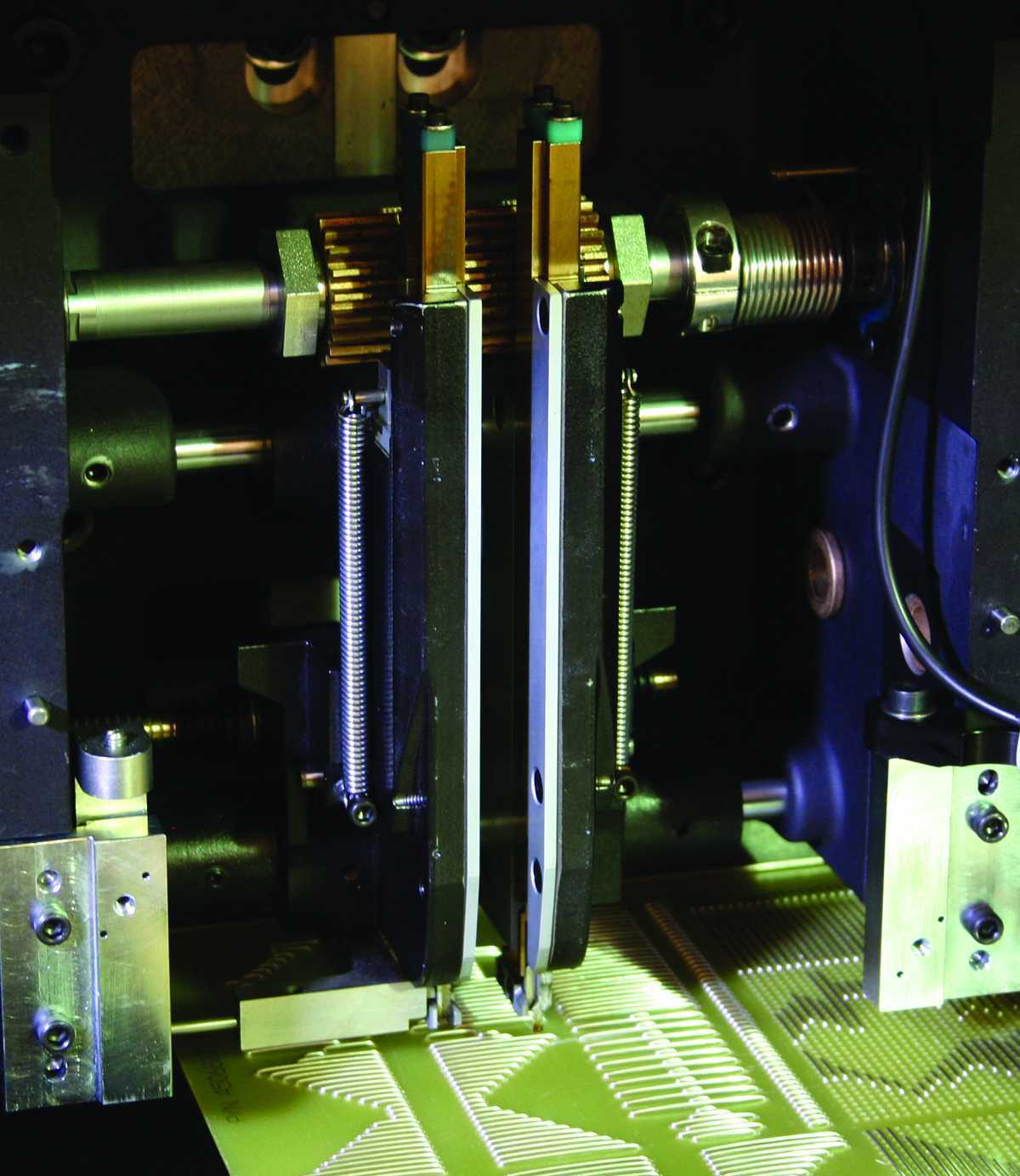
Default settings for Cambridge Heads:

Eyelet Head Pin Head Socket Head Terminal Head Square Wire Head
Head Routine Standard Intercnt Bowl Fed Intercnt Bowl Fed Intercnt Standard Intercnt Standard Intercnt
Low Parts Count 0 0 0 0 0
Shuttle Off Timer 100 100 100 100 100
Air Clean Timer 50 50 50 50 50
Head Delay 0 0 0 0 0
Part Settle Delay 20 20 20 20 20
Shuttle In Sensor no no no yes yes
Part Present Sensor yes yes yes no yes
Anvil Up Sensor yes yes yes yes yes
Anvil Aux Sensor no no no no no
Tooling Safe no no no yes no

Congratulation SOUTHERN MACHINERY has beed admitted as Foreign Member of ELCINA community

http://www.elcina.com

Electronic Industries Association of India identifies and bringstogetherlikeminded companies to represent the voice of Indian electronics and IT hardware industry and promote manufacturing.Electronic Industries Association of India promotes hardware manufacturing through active representation in the Government as well as scientific/technical institutions and industry/trade organisations in India and abroad.Electronic Industries Association of India represents to the government, problems faced by its members, individually or as a group, to find solutions and provide relief from unreasonable acts of administrative and policy making departments.

Electronic Industries Association of India provides a bouquet of professional and value-added services to its members. These services are tailored to serve the best interest of its Members and the Electronics/IT community to empower it to face competition and prosper. These services are constantly upgraded to suit the changing demands of the environment and needs of the industry.

Electronic Industries Association of India’s E-commerce facilities and its dynamic website together attract about 3500 visitors per day and provide a platform for members.

Electronic Industries Association of India is a repository of information and research, readily available for its members and helps them in taking critical decisions based on relevant facts.

Services currently provided by Electronic Industries Association of India to its members can be found by clicking here.