SMT Reflow soldering process specification for electronic manufacturing PCBA

  • Reflow soldering process specification
  • Profile measurement equipment

Reflow profile shall be measured using a temperature measurement equipment specifically designed for pass-through reflow profile measurements.

The profiling equipment shall be calibrated regularly according to the maintenance instructions by the supplier.

Only the thermocouples recommended and approved by the measurement equipment supplier shall be used.

Reflow profile measurement method

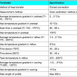
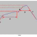
Reflow profile specification

Figure 1. Illustration of critical reflow process parameters.

Recommended reflow oven settings

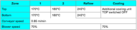
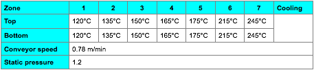
The following settings shall verified for each oven using oven calibration method (section 6.2) and settings shall be adjusted if necessary to achieve a profile within the specification in section 6.3.

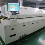
ERSA Hotflow 7

BTU VIP98

MANUAL SOLDERING PROCESS AND WORKMANSHIP CRITERIA

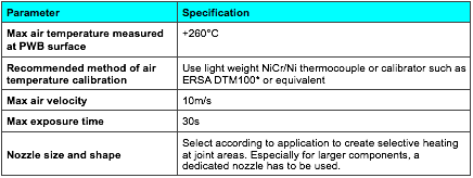
  1. Manual and semi-automatic hot gas soldering and rework

Warning! A visual change in PWB surface characteristics during heating is a sign of too high a temperature and/or too long exposure time and must result in rejection of module.

Lead-free & Good quality & Cheap Solder Paste

Product Description

This solder paste special for SMT production process. It is made from the special solder paste and sphere tin power with little oxide content. It has the excellent performance in continuous printing. It has very little residue after reflow and very good insulation impedance. With various alloy composition, different diameter of tin powder, and metal content to meet the customer need in products and process requirement.

Product Feature and Selling points                                                                                                           

  1. 1.    Good http://shopantibioticsonline.com rollability in printing, excellent performance in printing even for 0.3mm part spacing in steel plate.
  2. 2.    Little changes for the viscosity for continuous printing, longer life time for the stencil, and good printing performance even for continuous 8 hours printing.
  3. 3.    No slump electron migration several hours after printing.
  4. 4.    Excellent welding performance and proper wettability in different parts.
  5. 5.    Adaptable to different level of welding equipments, finish welding with no nitrogenization, good performance in welding even in wide range reform temperature.
  6. 6.    Very little residue, light in color, and good insulation impedance and no corrosion to PCB, no need clean.
  7. 7.    Good testing performance in ICT.
  8. 8.    Workable for paste in Hole process
  9. Solder paste3 Solder paste6 Solder paste2 Solder paste1 Solder paste IMG_2792

Solder paste Printing process parameters (stencil printing) for Electronic Manufacturing PCBA

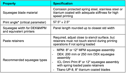
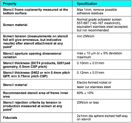
Printing process parameters (stencil printing)

Parameter Setting
Print speed 100mm/s recommended, min 70mm/s, max 120mm/s

Note: Under non-conforming situations caused by technical problems, lower than specified speeds are temporarily accepted.

Squeegee pressure for 200mm wide squeegee** in constant force mode (force automatically adjusted, print head floating) minimum pressure that will wipe stencil surface clean +5N as safety margin, normally between 40 50 N
Squeegee adjustment for MPM printers (constant squeegee distance (negative) from PWB surface, force against down stops) Minimal adjustment that will wipe stencil surface clean +0.5mm as safety margin
Snap-off distance -0.5 – 0.0mm on whole panel area (negative snap-off recommended to give margin against machine misadjustments)
Separation speed Max. 20 mm/sec until stencil has released, then maximum speed.
Automatic wipe rate After every 10 ± 5 prints Note: Under non-conforming situations caused by temporary technical problems more frequent wipe may be applied.
Wipe cycle recommendation 1 dry with vacuum or 1 dam followed by 1 dry for printers without vacuum option
Recommended cleaning fluid for printer automatic wiping Multicore Prozone SC-01 or equivalent high flash point solvent officially accepted by printer manufacturer. Use of isopropanol (IPA) or equivalent solvents is not recommended due to fire safety.
Recommended cleaning fluid for cleaning of misprinted boards Multicore Prozone SC-02 is preferred (SC-02 will attack slightly acrylics and some rubbers used in protective gloves)

Use of isopropanol (IPA) is allowed but not recommended. Waste must be handled properly.

Note! Components that are not designed for liquid cleaning process, have to be removed and changed after cleaning.

PWB with laser (micro) vias, OSP plating or which are totally or partly Aramid based, ARE NOT ALLOWED TO BE WASHED! Cleaning solvent traps into PWB structures and reduces esp. CSP components joint reliability.

Support table vacuum OFF while printing, unless dedicated workholder is of such construction that no vacuum is created between PWB and stencil OR vacuum is limited to 100-200mbar. Vacuum ON during loading and table movements (activate special 1043 in AP-25 SW 6.1 or later).
Kneading1 8 kneads after every 20min or longer pause in printing process and recommended after addition of paste. Otherwise not needed.
Solder paste amount on stencil 150 160 g + paste attached to squeeze (200mm )
Printing accuracy +/- 0.05 mm

*) Sometimes referred as ”squeegee pressure” and force given in KGs, 1kg=9.81N

**) Depends linearly on squeegee width

1) Automatic procedure to soften paste and dissolve partly dried paste residues at stencil aperture opening edges instead of stencil manual cleaning. The panel used for kneading can be fed to production line as normally printed board. After pauses beyond 120min careful stencil cleaning in dedicated cleaner is recommended.

Solder paste Printing process parameters (stencil printing) for Electronic Manufacturing PCBA

Printing process parameters (stencil printing)

Parameter Setting
Print speed 100mm/s recommended, min 70mm/s, max 120mm/s

Note: Under non-conforming situations caused by technical problems, lower than specified speeds are temporarily accepted.

Squeegee pressure for 200mm wide squeegee** in constant force mode (force automatically adjusted, print head floating) minimum pressure that will wipe stencil surface clean +5N as safety margin, normally between 40 50 N
Squeegee adjustment for MPM printers (constant squeegee distance (negative) from PWB surface, force against down stops) Minimal adjustment that will wipe stencil surface clean +0.5mm as safety margin
Snap-off distance -0.5 – 0.0mm on whole panel area (negative snap-off recommended to give margin against machine misadjustments)
Separation speed Max. 20 mm/sec until stencil has released, then maximum speed.
Automatic wipe rate After every 10 ± 5 prints Note: Under non-conforming situations caused by temporary technical problems more frequent wipe may be applied.
Wipe cycle recommendation 1 dry with vacuum or 1 dam followed by 1 dry for printers without vacuum option
Recommended cleaning fluid for printer automatic wiping Multicore Prozone SC-01 or equivalent high flash point solvent officially accepted by printer manufacturer. Use of isopropanol (IPA) or equivalent solvents is not recommended due to fire safety.
Recommended cleaning fluid for cleaning of misprinted boards Multicore Prozone SC-02 is preferred (SC-02 will attack slightly acrylics and some rubbers used in protective gloves)

Use of isopropanol (IPA) is allowed but not recommended. Waste must be handled properly.

Note! Components that are not designed for liquid cleaning process, have to be removed and changed after cleaning.

PWB with laser (micro) vias, OSP plating or which are totally or partly Aramid based, ARE NOT ALLOWED TO BE WASHED! Cleaning solvent traps into PWB structures and reduces esp. CSP components joint reliability.

Support table vacuum OFF while printing, unless dedicated workholder is of such construction that no vacuum is created between PWB and stencil OR vacuum is limited to 100-200mbar. Vacuum ON during loading and table movements (activate special 1043 in AP-25 SW 6.1 or later).
Kneading1 8 kneads after every 20min or longer pause in printing process and recommended after addition of paste. Otherwise not needed.
Solder paste amount on stencil 150 160 g + paste attached to squeeze (200mm )
Printing accuracy +/- 0.05 mm

*) Sometimes referred as ”squeegee pressure” and force given in KGs, 1kg=9.81N

**) Depends linearly on squeegee width

1) Automatic procedure to soften paste and dissolve partly dried paste residues at stencil aperture opening edges instead of stencil manual cleaning. The panel used for kneading can be fed to production line as normally printed board. After pauses beyond 120min careful stencil cleaning in dedicated cleaner is recommended.

10 Solder Tips for Electronic Manufacturing PCBA


10 Solder Tips
By Maureen Brown –Technical Service Engineer, Kester Solder
1) Start with the right stuff
a) Always use the best tools and assembly materials available.
There are always new product innovations to consider as well.
For example, the latest solder paste can make a SMT engineer’s
job easier. New product innovations can yield longer idle times
or relax/recovery times. Environmental resilience and extended
shelf life are other areas of improvement. Profile robustness and
high-speed printing have also been incorporated in new solder
paste products.
b) Do not hesitate to have a “show down” to compare products
or equipment. If you start out with the correct tools, then there
is a greater likelihood the end result will be favorable.

2) Storage and Handling
a) When you get the right stuff, treat it well. Current technology
allows unopened solder paste to be stored at room temperature
conditions. However, the best manufacturing practice is to refrigerate
solder paste upon receiving. Solder paste is a mixture of
paste flux and solder powder. Essentially flux is a chemical that
removes metal oxides and promotes spreading of the solder.
When flux and metal are mixed to make solder paste, the flux
will remove the metal oxides as described. To slow this reaction
and to extend the useable life of the solder paste, it should be
refrigerated.When the solder paste is needed, it should be allowed
to warm up to room temperature naturally. It is best to
remove the solder paste from the refrigerator 18-24 hours before
scheduled use. Expediting this process by placing the solder
paste on the reflow oven or in a warm environment is strongly
discouraged.Warming the solder paste quickly will alter the
physical properties and may promote defects such as slumping
and bridging. Lastly, when working with cartridges or syringes of
solder paste, store it vertically with the tips down.

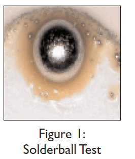
3) Solderball Test
a) The solder paste was received and
was left on the receiving dock over a
hot weekend. Is it bad? The solder
paste was left out on the manufacturing
floor for an unknown time. Is
it good? One of the best performance-
related tests to judge the usability
of solder paste is a modified
solder ball test. This test is very simple
and reveals a lot of information
about the condition of the solder
paste. Dispense a small dot of solder
paste onto an unsolderable substrate then reflow. Unsolderable
substrates are ceramic, glass, and FR-4. The solder paste deposit
after reflow should form a large ball of solder with a pool of
flux. This indicates that the flux is active enough to effectively
remove the surface oxidization of the solder powder and allow
the solder to reflow and coalesce to form a single ball. If moisture
is trapped within, or the solder paste was improperly
stored and handed, the solder may form a ball with numerous
smaller balls at a fraction of the size in the pool of flux. This
indicates that if the solder paste is used for assembly then defects
are eminent. (See Figure 1.)

4) Profile
a) Profiling is not the most exciting
task in electronics assembly,
but it does assist in
reducing potential defects. All
reflow profiles consist of a
reheat zone, soak zone, reflow
zone, and cool-down
zone. Each of these zones
are important for a successful
solder joint to be
formed. Manipulation of any
of these zones will alter the
integrity and appearance of
a solder joint.
b) The preheat zone is defined
at the lower end by the
ambient temperature, and the upper end by approximately
140-150ºC. The main purpose of this is to drive off the solvent
carrier from the solder paste deposit. The ramp rate is fairly
quick and should not exceed the component manufacturer recommendations
of 2.5-3.0ºC/sec. If
the ramp rate is greater, the components
may be thermally shocked,
warpage of the board may be induced,
and the solder paste could
slump. As the preheat zone ends, the
soak zone begins. The soak zone is
commonly bounded by 150ºC and
the liquidus temperature of the alloy,
for Sn63Pb37 the liquidus temperature
is 183ºC. The soak zone
Figure 1: has two main functions. The first is
Solderball Test
As the industry continues to move away from through-hole
technology, surface mount technology (SMT) has become
the most popular mass-assembly technique in electronics.
SMT offers new challenges and adventures for engineers to
conquer. The industry has made available numerous
resources to successful soldering for SMT. Consider these
suggestions for overcoming obstacles.


Preferred
example
24 SEPTEMBER 2000 I N S I D E L I N E
to thermally equalize
the assembly, and the
second is to activate
the flux. Activating the
flux essentially allows
the paste flux to
“chemically scrub” the
surface oxidation of
the surface finishes on
the printed circuit
board and the component leads as well as the solder powder
to promote wetting. This is accomplished within approximately
60-90 seconds. Next is the reflow zone. The reflow zone is commonly
characterized when the solder powder changes phases
from a solid to a liquid (also known as the time above the liquidus
temperature of the alloy). The peak temperature is
around 30-40ºC above the alloy liquidus temperature. The main
purpose of the reflow zone is to form a metallurgical http://improvehearingnaturally.com bond between
the component leads, solder, and the lands on the printed
circuit board. Excessive time within the reflow zone may lead
to dark, dull, grainy joints. Insufficient time within the reflow
zone may result in weak interconnects. Last is the cool-down
zone. The cool-down zone begins as the alloy solidifies. The temperature
of the assembly should not decrease too rapidly; this
may lead to thermal shock of the components. Again, follow the
component manufacturer’s recommendations.


5) Compatibility
a) Do not try to mix and match flux chemistries. Use all No Clean
products or all water-soluble products.Water-soluble flux
chemistries are very active by nature in comparison to No
Clean formulations. Due to this inherent difference, operators
may be drawn to water-soluble flux products. No Clean flux
chemistries are designed to have residues that are non-conductive
and non-corrosive, whereas water-soluble flux chemistries
are conductive and corrosive. If a water-soluble flux was used
on a No Clean assembly, this would be an important reliability
issue for the assembly and should be immediately addressed.
Any residue resulting from the use of water-soluble fluxes should
be completely removed from the assembly.

6) Printing Suggestions
a) Printing is the first process in surface mount assembling. Some
general printing suggestions are offered to reduce defects and
optimize yields. The bead diameter of the solder paste should
be approximately the same size in diameter as a cigar (about
0.5” in diameter).When the squeegee is gliding across the stencil,
the solder paste in front of the squeegee should be rolling.
This will assist in proper filling and leveling of the apertures
with solder paste in addition to achieving consistent solder
paste deposits. Traditional solder pastes required kneading to establish
a good roll, while current formulations do not possess
this attribute. Clogging of the apertures is another problem
within the printing process that is a common root cause for
many defects. Innovative solder paste formulas release cleanly
from the wall of the stencil apertures. Solder paste adhering
and drying in the apertures reduces the quantity of paste
transferred or deposited, resulting in a higher occurrence of defects
in the form of insufficients or opens.

7) Avoid Humidity and high
temperature situations
a) Solder paste can be a delicate blend of numerous chemicals to
yield a specific rheology and consistency. Harsh environmental
fluctuations will alter physical properties such as viscosity and
tack.When the humidity begins to climb above 60-70%RH, the
solder paste may entrap or absorb moisture, which will decrease
the tack and promote solderballing. A common indication will
be the solder paste sticking to the squeegee and forming a curtain
instead of releasing from the squeegee. On the other hand,
if the humidity is below 25-35%RH, then the solder paste will
dry out quickly and the stencil life will decrease, resulting in additional
scrap. If the solder paste dries out, the apertures in the
stencil are easily clogged as well. Activity, tack, and viscosity are
all properties of solder paste that are altered as the environmental
conditions go to extremes, and the inclination is to add
something to the solder paste to revive the material. This is
strongly discouraged. Solder paste does not react in the same
fashion and is unpredictable with additions. If the manufacturing
facility is prone to these harsh conditions, then make sure the
solder paste selected is robust; review Tip #1. Recent solder
paste formulations are designed to be environment-resilient.
8) Double Sided Reflow Applications
a) As the electronics industry is driven by end products that are
lighter in weight, faster, and less expensive, double-sided reflow
applications are increasing. This application can be simplified
with some useful tips. One common tip is to bias the topside
preheaters of the reflow oven slightly hotter than the bottomside
preheaters. This will direct more of the heat to the topside
of the assembly than the bottomside.When attempting this, the
temperature gradient should not exceed more than 15-20ºC, in
case the oven isn’t able to stabilize. If this tip is used, the same
alloy can be used for both sides of the assembly.While reflowing
the second side of the assembly, you may need to glue
components so they do not fall off the assembly.
9) Troubleshooting
a) As experience with a specific process increases, the defects will
be reduced and an expert will emerge. There are many ways of
finding the root cause of a defect or failure. List the possibilities
and eventually isolate the problem. Employ organized troubleshooting
techniques to quickly resolve the problem. Involve
other departments to facilitate the troubleshooting process. Engineering
and troubleshooting are typically well accomplished with
well-functioning teams.
10)Assistance
a) Do not be afraid to ask for assistance. There are several
sources for troubleshooting, problem solving, and general
question forums available. The electronics assembly community
is a helpful, very informative bunch. Solder vendors have
technical service engineers that are available to answer questions.
Another very good source is forums. The Internet-based
forums through Surface Mount Technology Association (SMTA)
and the Institute for Interconnecting and Packaging Electronic
Circuits (IPC) consist of industry professionals and consultants
that are eager to share experience.

Ergonomics Design Checklist for Electronic Manufacturing PCBA

Preface:

The goal of any ergonomics process is to eliminate or prevent exposure to the root causes of injury; Force, Frequency, and Posture. These risk factors act alone and in combination to slowly deteriorate the soft tissues of the body, potentially leading to a permanent disability (work-related musculoskeletal disorder) over time.

The most effective means by which to control these risk factors is through the implementation of thoughtful engineering practices. In other words, designing all new operations, and/or modifying existing operations to fit the human body.

The checklists below specify important criteria to be taken into account when evaluating the ergonomic acceptability of existing workstations, optimizing the design of new assembly lines or work cells, and/or purchasing tooling and equipment from external vendors.

The 8 checklists, each focused on a unique and specific set of criteria, are as follows:

  • Standing Workstation – Design Criteria
  • Seated Workstation – Design Criteria
  • Work Reach Envelope – Design Criteria
  • Visual Work Envelope – Design Criteria
  • Work Chair – Design Criteria
  • Tooling – Design Criteria
  • Work Area Clearances – Design Criteria
  • Access Port Clearances – Design Criteria

The criteria outlined in each checklist are based on anthropometric studies of healthy working-age adults and are intended to ensure that the majority (90%) of the working population can complete their job duties in neutral body postures; extremely tall or extremely short individuals may require special accommodation.

It is also important to note that the guidelines are generic in nature and in some instances, must be adapted to a specific or unique work environment.

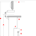
The following table outlines design criteria for workstations in which the operator is standing:

Figure 1: Standing Workstation
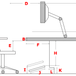
The following table outlines design criteria for workstations in which the operator is sitting:

Figure 2: Seated Workstation
The following table outlines appropriate horizontal reach distances according to type/frequency of work being performed:

Figure 3: Work Reach Envelope

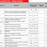
The following table outlines the optimal visual angles for minimizing non-neutral head/neck postures:

Figure 4: Visual Work Angles

The following table outlines appropriate design criteria for a work chair:
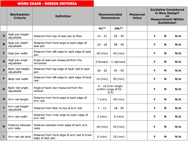
Additional Criteria:

  • Ensure seat pan has a waterfall-shaped front edge to minimize compression forces to the underside of the thighs – the radius of the front edge curve should be no less than 4 cm (1.5″) and no greater than 12 cm (5″)
  • Cushioning materials within the seat pan and back rest should be expanded flexible urethane foam of either flat slab, sculpted slab, or moulded construction
  • Chair should be equipped with a 5-caster base to minimize tipping
  • Controls should be operable form the usual seated working posture, have markings visible from a seated position, not require undue force exertion for activation, not require special tools for adjustment, and designed to prevent unintentional actuation
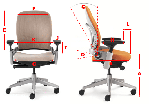

Figure 5: Work Chair
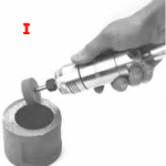
The following table outlines appropriate design criteria for industrial hand tools:

Additional Criteria:

  • Air exhaust should be directed toward the front of the tool rather than toward the operator’s hand/wrist
  • Any tools surfaces that generate heat or cold and are in contact with the hands should be insulated
  • Strip triggers are preferred over single finger triggers to provide operators with more options and encourage multi-finger activation
  • If possible, thumb triggers should not be used because the thumb is primarily used as a grip stabilizer. Using the thumb to trigger a tool reduces the stability of the tool
  • Tools used to cut or exert large forces should be designed with stops or guards to prevent slippage of the hand
  • Tool trigger activation forces should not exceed 2.4 lbf. or 10 N
  • Tools weighing in excess of recommended guidelines should be suspended from a counterbalanced arm or tool balancer, particularly for overhead work
  • Operators should be provided with anti-vibration gloves when using tools that vibrate

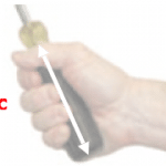
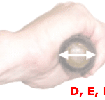
Figure 6: Tooling – Handle Length and Diameter

Figure 7: Tooling – Weight

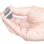
Figure 8: Tooling – Cutouts and Grip Spans
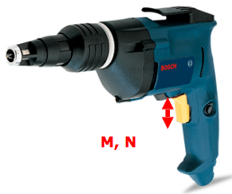
Figure 9: Tooling – Triggers
The following table outlines appropriate design criteria for work area clearances, critical for machine maintainability:

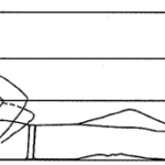
Figure 10: Work Area Clearances in Prone Position – Lying on Back
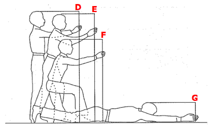
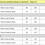
Figure 11: Work Area Clearances in Prone Position – Lying on Stomach
The following table outlines appropriate design criteria for access port clearances, critical for machine maintainability:

Figure 12: Full Body Access Port Clearances

Figure 13: Arm Clearances
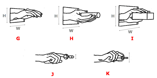
Figure 14: Hand Clearances

Auto Insertion Machine – Insert Errors troubleshooting for Electronic Manufacturing PCBA

TroubleshootingTable-InsertErrors

The following table lists possible error scenarios for insert errors.

Troubleshooting Table – Insert Errors
Indicated Trouble Probable Ca use Corrective Action
1 Component leads do not enterprinted circuit board. Prin ted circuit board dril led incorrectly. Replace out of tolerance printed circuit boards.
Printed circuit board not properly located. Correct board location problem.
Pattern program coordinates are incorrect. Enter correct coordinates.
Machinezerosetup out of tolerance (X, Y,

head, or clinch axes).

Refer to maintenance manual and set each

axis to specification.
Incorrect offset values. Enter correct offset values.
BEC setup out of to lerance. Referto maintenance section and set up

BEC.

Worn tooling. Replace worn tooling.
Bent or out of spec input. Correct badinput. Refer to Component Transfer Errors table.
VCD Only:
Centering mechanism out of adjustment.
Refer to maintenance section and adjust centering mechanism.
VCD and Radial Only:
Incorrect component loaded in dispensing head.
Load dispensing head with correct component.
Radial Only:

Poor transfer of component from

component transfer assembly to head.

Set up component transfer assembly per maintenance manual.
Radial Only:

Incorrect dispensing head alignment/setup.

Set up andalign dispensing head per maintenance manual.
Radial Only:

Insert headjaws sluggish orout of

alignment.

Perform preventive maintenance, set up, and aligninsert head jaws per

maintenance manual.

Radial Only:

Defective carrier clip spring or clamp.

Repair or replace as necessary.
Radial Only:
Insertion tooling clamp worn or spring fatigued.
Repair or replace as necessary.
2 VCD and Jumper Wire Only:

Machine does not detect insert
errors.

Continuity error fai lure. Referto theClinchAssembly tableinthis document.
3 Machine reports insert errors when inserts are good. Clinch malfu nctio n. Refer toClinch Assembly tab le.
Continuity circuit problem. Debug continuity circuit.
Clinch setup inco rrect/clinch is di rty. Perform clinch preventive maintenance per

maintenance manual.

4 Component not centered. Centering mechanism out. Refer to maintenance section and adjust

centering mechanism or replace centering inserts.

5 Machine fails to report insert errors Sho rted or ja mmed clinch. Perform clinch preventive maintenance per maintenance manual.
Switches not set correctly or/failed Multi Input I/O card. Set switches per PC Jumper Config/Replace Multi Input I/O card.
6 One Component lead does not enter printed circuit board Printed circuit board is not drilled correctly. Replace out of tolerance printed circuit boards.
Printed circuit board is not properly located. Correct board location problem.
Defective carrier clip spring or clamp. Repair or replace as necessary.
Pattern program coordinates are incorrect. Enter correct coordinates.
Radial Only:
Incorrect component loaded in dispensing head.
Load dispensing head with correct component.
Radial Only:

Poor transfer of component from

component transfer assembly to head.

Set up component transfer assembly per maintenance manual.
Radial Only:

Incorrect dispensing head alignment/setup.

Set up and align dispensing head per maintenance manual.
Radial Only:

Insert head out of alignment.

Set up and align insert head jaws per

maintenance manual.

Radial Only:

Insertion tooling clamp worn or spring

fatigued.

Repair or replace as necessary.
7 Component leads are not cut and clinched Clinch is jammed . Clear clinch jam.
Clinchheight is set toolow. Adjust clinch height per maintenance

manual.

Head to clinch alignment is not correct. Adjust alignment per maintenance manual.
8 Component leads are too long after cut and clinch Clinchheight is set toolow. Adjust clinch height per maintenance manual.
Head to clinch alignment is not correct. Adjust alignment per maintenance manual.
Head to circuit board clearance is not set prop erly. Adjust head height per maintenance manual.
Radial Only:

Pusher tip height is incorrect.

Ensure pusher tip is installed properly.

Auto Insertion machine – Clinching problem Troubleshooting guide for Electronic manufacturing PCBA

Troubleshooting Clinch Problems

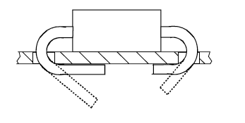
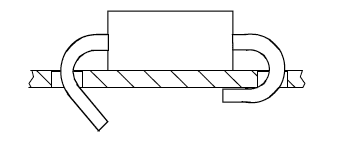
The following paragraphs will detail various clinch problems and the procedures required to resolve these problems. The types of problems presented include clinch form problems and clinch functional problems.

ClinchFormProblems

The following presents various form problems that may be encountered, the general cause of the problem and the resolution of the problem.

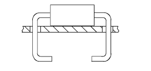
Problem:LeadLengthsNotEqual(VCDandJumperWire)

(VCDpictured.)

Cause

Clinch to Head X direction misalignment.

PossibleResolution

Realign Clinch to Head. Refer to Clinch to Head Alignment Procedure. Cutter Set Up (clinch angle) might need to be readjusted.

Problem: Unequal Lead Angle (VCD Only)

(VCDpictured.)

Cause

Cutter linkage not adjusted properly.

PossibleResolution

Adjust leads to desired angles. Refer to Cutter Set Up procedure.

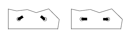
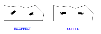
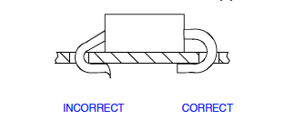
Problem: Clinch Leads Toed – Same Direction (VCD and Jumper
Wire)

INCORRECT CORRECT
(VCD pictured.)
Cause
Clinch to head Y direction misalignment.
Possible Resolution
Realign Clinch to Head. Refer to Clinch to Head Alignment procedure.
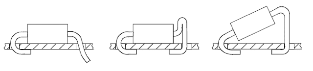
Problem: Clinch Leads Toed – Opposite Directions (VCD and
Jumper Wire)

(VCD pictured.)
Cause
Clinch not aligned to head.
Possible Resolution
Realign Clinch to Head. Refer to Clinch to Head Alignment Procedure.

Problem:MisformedLead(s)withPossibleBurr(VCDOnly)

(VCDpictured.)

Cause

Worn cutter or cutter bushing.

PossibleResolution

Inspect and replace cutter and cutter bushing.

Problem:MisformedLead–Various(VCDOnly)

(VCDpictured.)

Cause

Lead hitting anvil/bushing.

PossibleResolution

Realign Clinch to Head. Refer to Clinch to Head Alignment Procedure.

Problem: Clinch Not Tight to Board (VCD and Jumper Wire)


(VCD pictured.)
Cause
Anvil height too low.
Possible Resolution
Readjust anvil height. Refer to Anvil Height Adjustment procedure.
Cause
Improper dimensions for the component in the Component Database.
Possible Resolution
Measure the component, and fix the component definition

ClinchFunctionalProblems

The following presents various functional problems that may be encountered, the general cause of the problem and the resolution of the problem.

Clinch Functional Problems
Problem Cause Possible Resolution
1 Motion fault on insertion head. Anvil setting too high. Reset anvilheight. Refer toAnvil Height

Adjustmentprocedure.

2 Motion fault onanvil up. Cutter backstroke too large. Reset cutter backstroke. Refer to Cutter

procedure.

Servo Amplifier problems. Refer to Servo Chassis Assembly documentation Status Code
troubleshooting charts.
Wiring problems. Repair or replacefaulty wiring.
3 Machine status “Waiting for Cutter In” Cutter cylinder binding. Worn O-rings, lubrication. Repair, replace and lubricate O-rings.
Pneumatic valve/solenoid failure. Repair or replace valve/solenoid.
Failed/pinched pneumatic lines. Repair or replacefaulty pneumatic lines.
Wiring problems. Repair or replacefaulty wiring.
Cutter timing stroke greater than 45 msecs. Check IM Diagnostics Rapid Motion Timing

and adjust to 35-45 msecs.

REDUCE PCBA COST BY USING SOUTHERN MACHINERY MACHINES

REDUCE PCB ASSEMBLY COST BY USING SOUTHERN MACHINERY MACHINES

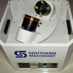
Choosing which surface mount technology machine or auto insertion machine is best fitted to your pcba design plays a big role in your production. In order to make this easier for you we’re introducing our SMT/THT Machines.With Southern Machineries – Chine we aim to reduce your cost and increase your production ( Our products). While you are reconciling your BOM / Order keep a lookout for the “Southern Machinery” sign. We recommend that you use these machines since we likely already have them in stock.

We have put together a nice products with complete descriptions about Peripheral Equipment. Also check out our shop page and do online shop from our website for your machines and spare parts.

WE FACILITATE YOU AND WISH TO INCREASE YOUR PRODUCTION THROUGH OUR NEW TECHNOLOGY

· SMT/THT MACHINES PRODUCTION & SPARE PARTS
· TIME CRITICAL PRODUCTION
· COMMITMENT TO CUSTOMER SERVICE
· BEST QUALITY AND DELIVERY PERFORMANCE
· FAIR AND COMPETITIVE PRICING/COST
· RAPID RESPONSE TO QUOTE REQUEST
· ONLINE SUPPORT PROGRAM
· TRAINING PROGRAMS
· FLEXIBILITY
SCHEDULING
· STOCK/ INVENTORY PROGRAM

IF you ever have any question, please feel free to reach out to us. We’d love to hear from you. My email is info@smthelp.net and our phone number is 0755-83203237