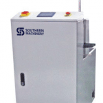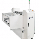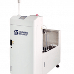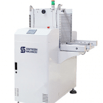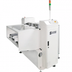
USA IPC APEX EXPO 2016, You are warmly welcome to visit our booth No. :#2930.

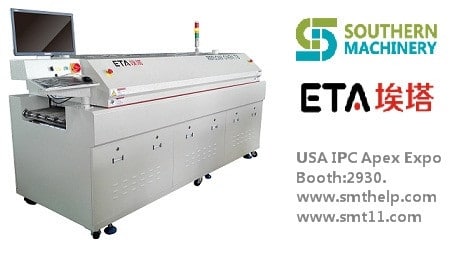
ETA T series Lead-free reflow oven(T8/T10/T12):

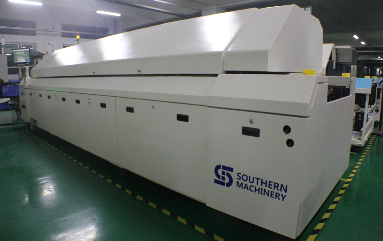
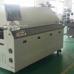
ETA T series lead-free reflow oven is ETA’s mature product after years of market testing.T series Reflow oven has maintained a larger share of the market for many years. Its unparalleled heating performance and temperature control system meets the requirements of various welding processes, It is ETA’s crystallization of years technical research and development.

USA IPC APEX EXPO 2016, You are warmly welcome to visit our booth No. :#2930.

www.smthelp.net,www.smt11.com

AI, Auto Insertion : Axial Inserter; Radial Inserter; JW (Jumper Wire) Inserter; Odd form Inserter; PIN inserter; Eyelet Inserter; Terminal Inserter IM, Insertion Mount, MI,Manual Insertion, DIP, Wave soldering 5, SMT - Souface Mount Technology: BHS: PCB board handling system, Loader, Unloader, Conveyor,Shuttle Printer: Solder paste screen printer SPI: Solder Paste Inspection Mounter: Chip Mounter, Pick and Place, IC Mounter, High Speed Mounter AOI Reflow Oven

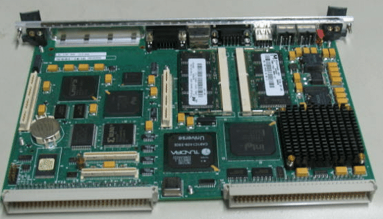
Auto Insertion machine CPU board EPC-1316 Boot Sector and BIOS Corruption Procedure for Re-flash

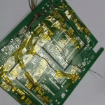
48797301 board
Procedure

Symptoms of corrupted BIOS and/or Boot Block:

  • No video signal from the EPC-1316
  • No activity on
  1. The keyboard, no status lights at power-on
  2. The floppy drive with a disk in or out
  3. The hard disk drive evident by the light off after a certain amount of time
  • The EPC-1316 is trying to access the CD-ROM drive with failed attempts every second or so.
  • The EPC-1316 is in this cycle indefinitely

Steps to take:

  1. Power down the EPC-1316 board/machine.
  2. Make sure that this instructions file is opened on a different computer.
  3. At the last step of these instructions is an embedded object of the .zip folder; it contains all of the files needed for this procedure.
  4. Right click on the .zip folder, select ‘Package Object’ and click on ‘Activate Contents’. If a message regarding a trustworthy source is displayed, confirm that this source can be trusted
  5. Create a new folder on the Desktop and rename it to “EPC-16FBD1.00.10”
  6. Click ‘File’, then select and click on ‘Extract All…’
  7. Extract the .zip folder into the folder on the Desktop, created in Step 3.
  8. Obtain a 3.5in Floppy Disk and insert it into the drive.
  9. Open the “EPC-16FBD1.00.10” folder from the Desktop
  10. To run an MS-DOS program, double click on the CRISDISK.BAT file.
  11. To run a Windows Application, double click on the WINCRIS.EXE file.
  12. Go through prompts of the program attentively; and a crisis disk will be created.
  13. Remove the EPC-16 board from the VME chassis/rack.
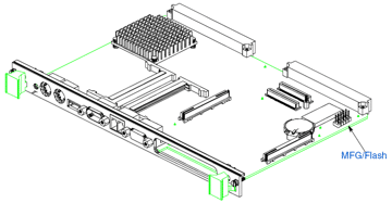
  14. At the bottom of the board there are 2 x 5 jumper pins: MFG/Flash. (Figure 1)


Figure 1 EPC-1316 Board jumper pin location

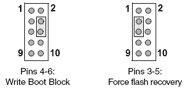
  1. See Figure 2 for PIN-out of the Jumper pins.


Figure 2 EPC-1316 Board jumper pin numbering

  1. Using 2 jumpers (Figure 3): place one to jumper pins 4-6. (jumper setting ‘Write Boot Block’)
  2. Place the second to jumper pins 3-5. (jumper setting ‘Force flash recovery’)


Figure 3 EPC-1316 Board flash jumpers configuration

  1. Replace the EPC-1316 board to the VME chassis/rack.
  2. Insert the 3.5in Floppy Disk that was created from the steps above into the floppy drive.
  3. Power-up the machine/chassis/EPC-1316.
  4. If the status light on the floppy drive comes on and stays on, then the floppy disk is being accessed.
  5. When the floppy drive stops accessing the Floppy Disk, wait about 5 seconds, and then remove the disk.
  6. Power down the EPC-1316, and remove it from the VME interface.
  7. Remove jumpers from the board and replace the board to the VME interface.
  8. Power-up the machine/chassis/EPC-1316 and make sure that it boots the operating system.
  9. Refer to UIC procedures for proper BIOS settings/ configuration


UIC, EPC-1316 Boot Sector and BIOS Corruption Procedure for Re-flash

Procedure

Symptoms of corrupted BIOS and/or Boot Block:

  • No video signal from the EPC-1316
  • No activity on
  1. The keyboard, no status lights at power-on
  2. The floppy drive with a disk in or out
  3. The hard disk drive evident by the light off after a certain amount of time
  • The EPC-1316 is trying to access the CD-ROM drive with failed attempts every second or so.
  • The EPC-1316 is in this cycle indefinitely

Steps to take:

    1. Power down the EPC-1316 board/machine.
    2. Make sure that this instructions file is opened on a different computer.
    3. At the last step of these instructions is an embedded object of the .zip folder; it contains all of the files needed for this procedure.
    4. Right click on the .zip folder, select ‘Package Object’ and click on ‘Activate Contents’.  If a message regarding a trustworthy source is displayed, confirm that this source can be trusted
    5. Create a new folder on the Desktop and rename it to “EPC-16FBD1.00.10”
    6. Click ‘File’, then select and click on ‘Extract All…’
    7. Extract the .zip folder into the folder on the Desktop, created in Step 3.
    8. Obtain a 3.5in Floppy Disk and insert it into the drive.
    9. Open the “EPC-16FBD1.00.10” folder from the Desktop
    10. To run an MS-DOS program, double click on the CRISDISK.BAT file.
    11. To run a Windows Application, double click on the WINCRIS.EXE file.
    12. Go through prompts of the program attentively; and a crisis disk will be created.
    13. Remove the EPC-16 board from the VME chassis/rack.
    14. At the bottom of the board there are 2 x 5 jumper pins: MFG/Flash. (Figure 1)

Figure 1 EPC-1316 Board jumper pin location

    1. See Figure 2 for PIN-out of the Jumper pins.


Figure 2 EPC-1316 Board jumper pin numbering

    1. Using 2 jumpers (Figure 3): place one to jumper pins 4-6. (jumper setting ‘Write Boot Block’)
    2. Place the second to jumper pins 3-5. (jumper setting ‘Force flash recovery’)

Figure 3 EPC-1316 Board flash jumpers configuration

    1. Replace the EPC-1316 board to the VME chassis/rack.
    2. Insert the 3.5in Floppy Disk that was created from the steps above into the floppy drive.
    3. Power-up the machine/chassis/EPC-1316.
    4. If the status light on the floppy drive comes on and stays on, then the floppy disk is being accessed.
    5. When the floppy drive stops accessing the Floppy Disk, wait about 5 seconds, and then remove the disk.
    6. Power down the EPC-1316, and remove it from the VME interface.
    7. Remove jumpers from the board and replace the board to the VME interface.
    8. Power-up the machine/chassis/EPC-1316 and make sure that it boots the operating system.
    9. Refer to UIC procedures for proper BIOS settings/ configuration


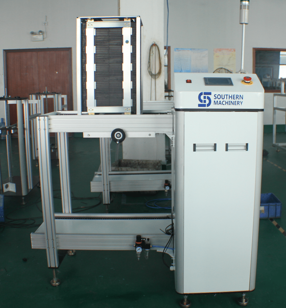
SMT PCB board handling Vacuum Bare Board Loader Product Checklist

Vacuum Bare Board Loader Finished Product Checklist

Mechanical
___ ___ ___ FULL WIDTH RANGE (3”- 20”) AVAILABLE
___ ___ ___ SMOOTH UP/DOWN, OPERATION
___ ___ ___ VACUUM CUPS EASILY ADJUSTED TO FULL RANGE
___ ___ ___ TRANSFER RAILS, PARALLEL/SQUARED/HEIGHT
___ ___ ___ AC TSD ASSY INSTALLED AND FREE SLIDING
___ ___ ___ VERIFY ROLLERS DO NOT BIND
___ ___ ___ BOARD GUIDES INSTALLED AND ADJUSTABLE
___ ___ ___ HAND CRANK ASSY INSTALLED AND OPERABLE
___ ___ ___ VERIFY TRANSFER RAIL CYLINDERS OPERATE PROPERLY
___ ___ ___ INTERFACE BRACKETS ATTACHED

Electrical
____ ___ ___ HIPOT TEST: RESULT _______________________ TECHNICIAN: _________________
___ ___ ___ GROUND CONTINUITY RESULT ______________ < 0.17 OHM
___ ___ ___ E-STOP(S) OPERABLE, STOP BUTTON OPERABLE
___ ___ ___ DOOR CLOSED SENSORS AND STACK EMPTY SENSOR FUNCTIONING
___ ___ ___ IF SMEMA INTERFACE
___ ___ ___ BE SURE SEMA INTERFACE CABLE IS INCLUDED
___ ___ ___ OPERATION MODE SELECTOR SWITCH INSTALLED AND OPERATIONAL
___ ___ ___ VERIFY BELT SPEED ADJ RANGE

Hardware
___ ___ ___ LEVELING PADS LOCKED
___ ___ ___ HARDWARE TIGHTENED

Functional
___ ___ ___ ALL REQUIRED PRIOR INSPECTION(S) COMPLETED AND PASSED
___ ___ ___ 500 BOARD RUN COMPLETE, NO ERRORS
___ ___ ___ VERIFY INTERFACE FUNCTIONS _____ SMEM

SMT PCB Boards Conveyor manufacturing Checklist for Electronic Manufacturing PCBA

Conveyor Finished Product Checklist
Mechanical

___ ___ ___ FULL WIDTH RANGE (2-18”) AVAILABLE
___ ___ ___ TRANSFER RAILS: SQUARED / PARALLEL / HEIGHT
___ ___ ___ WORKSTATION INSTALLED
___ ___ ___ COVERS – VERIFY CONSISTENCY AMONG COVERS FOR ALL CONVEYORS ON THE ORDER
___ ___ ___ AC TSD ASSY INSTALLED & FREE SLIDING
___ ___ ___ VERIFY ROLLERS DO NOT BIND
___ ___ ___ PUSHER INSTALLED AND FUNCTIONAL
___ ___ ___ PULLEY GUARDS MOUNTED
___ ___ ___ INTERFACE BRACKETS ATTACHED

Electrical
___ ___ ___ HIPOT TEST: RESULT_________ <5 mA TECHNICIAN ______________________
___ ___ ___ GROUND CONTINUITY RESULT ____________________________< 0.17 OHM
___ ___ ___ DRY CYCLE RUN COMPLETE – 1 HOUR
___ ___ ___ “INSPECT” INSTALLED AND OPERABLE, VERIFY CORRECT LOCATION
___ ___ ___ “E-STOP(S)”, “ERROR(S)” INSTALLED AND OPERABLE
___ ___ ___ MIDRANGE MOTORS (11.5:1), IDLER PULLEYS (FREE SPINNING)
___ ___ ___ IF SMEMA INTERFACE, BE SURE SMEMA INTERFACE CABLE IS INCLUDED
___ ___ ___ VERIFY SPEED ADJ RANGE
___ ___ ___ VERIFY X-FORMER IS NOT NOISY
___ ___ ___ FUSE LABEL APPLIED ON CANADIAN ORDERS ONLY

Hardware
___ ___ ___ LEVELING PADS LOCKED DOWN
___ ___ ___ HARDWARE TIGHTENED (LEGS, WIDTH SUPPORTS, RAILS)

Functional
___ ___ ___ VERIFY BOARD TRANSFER (SMEMA FUNCTIONALITY)

PCB Board Handling Dimension Setups for Electronic Manufacturing PCBA

Board Handling Dimension Setups

To provide manufacturing instructions for setup and verification of Board Handling

dimensions on machine.

Process instructions:

Sign off on critical checklist as you proceed through each step to indicate completion of each

process. Do NOT leave sign-offs until the end of the process!

1. PARALLELISM

NOTE: 1) Staged/ dual lane board handling must be parallel within .030” for 5MM and .020” for 3MM clearance.

2) All measurements should be taken with feeler guages at the moveable rail.

3) The fixed rail(s) should never be adjusted (if out of spec, see engineering).

4) This test is performed in the unclamped position.

1. Power down machine.

2. Manually close PWC to 6 inches.

3. Remove card clamp from the moveable rail(s) and flip upside down (not end to end) and replace screws. This is

done to keep the board handling rigid. Not possible with dual lane 8.5 inches inbound (just remove clamp).

4. Take the special 6 in. cutout board and move along the bd. handling belts and find the tightest spot (0.000”) on the

board handling.

5. Check the 6 other locations throughout board handling and record all 7 on the checklist.

There are going to be 7 points along the board handling that are measured. Those points are as follows:

1) Left end

2) Over the left leadscrew

3) Left most dowel pin on the card guide

4) Center dowel pin

5) Right most dowel pin

6) Over the right leadscrew

7) Right end
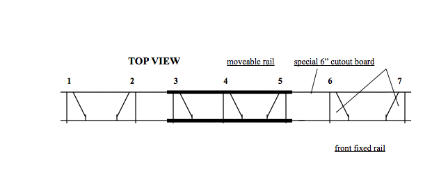
NOTE: When done, put card clamp(s) back to their original position.

front fixed rail

2. FEEDER BANK TO INSIDE EDGE OF LIFT ASSY.

Measure with a set of verniers the distance between the front of the feeder upright to the inside edge of the Lift Assy.

as shown.

3. FIXED RAIL TO FIXED RAIL (Dual lane only)

1. Measure with a long set of verniers the distance between the front fixed rail (from the inside card guide) to the center

fixed rail (from the inside card guide). Remember when acquiring this measurement to add .2 to the total to account

for the front vernier nib.

2. Measure in 4 locations. Above the left and right outermost locations on the board handling (align with the outermost

card guide bolts for reference) and above the left and right board handling lead screws (align with the card guide bolts

just above the lead screws for reference).

3. Record the results on the checklist.

4. HEIGHT

1. Place the reference block in the left slot of the positioning system base.

2. Place the correct reference plate in PWC and tighten.

3. The center mapping plate will be used to check focal range and coplanarity. When doing this check observe

the following precautions: check for burrs on the bottom of the Height guage indicator, when checking the 4

corners on the glass part of the plate do not drag the bottom of the indicator across the fiducials, if the indicator

movement scratches the surface stop immediately.

4. Clamp down plate by hooking up a manual air fixture (Day 2-3) or by selecting Mach. status/Diagnostics/

Discrete I-O/Board Handling and then highlighting either Bd Clmp Loc Sup Lane 1 or Bd Clmp Loc Sup Lane 2.

Select Set outputs to clamp up and reset outputs to release clamp (Day 4 – on).

5. Each phase should be checking the height the same. Either with or without the Board supports.

6. Place the height guage indicator on the head mounting surface.

7. With the indicator, set the top of the reference block to zero.

8. Check the 4 corners of the plate with the indicator.

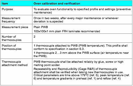
SMT Reflow Oven profile measurement method for Electronic Manufacturing PCBA

  1. Reflow profile measurement method

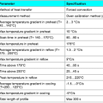
Reflow profile specification

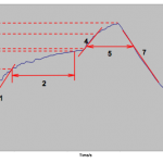
Figure 1. Illustration of critical reflow process parameters.

Recommended reflow oven settings

The following settings shall verified for each oven using oven calibration method (section 6.2) and settings shall be adjusted if necessary to achieve a profile within the specification in section 6.3.

ERSA Hotflow 7

AI spare parts、Universal Parts,UIC,TDK.VCD Sequencer.SMT,THT,PCB,PCBA,AI,wave soldering,reflow oven,nozzle,feeder,wave soldering,PCB Assembly, LED, LED lamp, LED display

ETA and Southern Machinery will attend the USA IPC APEX EXPO 2016 exhibition

ETA and Southern Machinery will attend the USA IPC APEX EXPO 2016 exhibition to share the industry’s top feast.


You are warmly welcome to visit our booth No. :#2930 in USA IPC APEX EXPO (Mar. 15th-Mar17, 2016)

As the industry’s leading manufacturers, ETA would show our latest T-series lead-free reflow oven together with Southern Machinery in USA IPC APEX EXPO 2016 exhibition.This is unique machine in China now. It refreshes the traditional perception of reflow oven. T-series lead-free reflow oven could ensure the lead-free process optimization under the condition of the smallest footprint and the lowest power consumption. It could meet all customer’s demand. Meanwhile, Many new special equipment will also be displayed at this show.

ETA is the professional manufacturer of reflow oven and offer full SMT solutions for customers. We have more than 20 years experience and technology in SMT filed. The most professional term and the best service are waiting for you. Our goal is to provide the reliable full SMT solutions to all the customers around the world. Southern Machinery is our good global partner. We would provide the high-value technical support to our customers together.

www.smt11.com,

www.smthelp.net

You are warmly welcome to visit our booth No. :#2930.

AI spare parts、Universal Parts,UIC,TDK.VCD Sequencer.SMT,THT,PCB,PCBA,AI,wave soldering,reflow oven,nozzle,feeder,wave soldering,PCB Assembly, LED, LED lamp, LED display

AI spare parts、Universal Parts,UIC,TDK.VCD Sequencer.SMT,THT,PCB,PCBA,AI,wave soldering,reflow oven,nozzle,feeder,wave soldering,PCB Assembly, LED, LED lamp, LED display
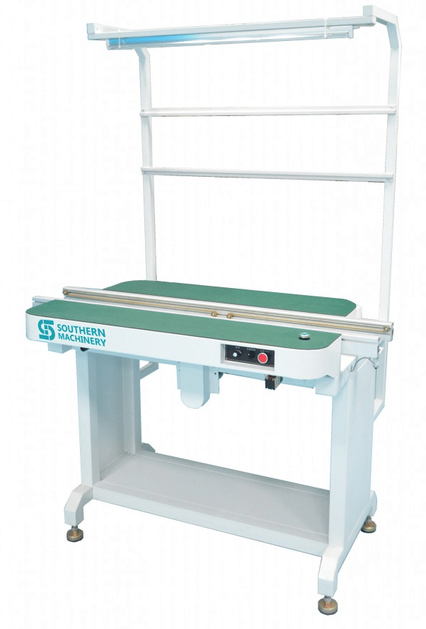
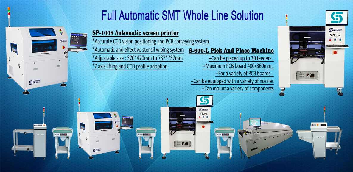
Southern Machinery:Provide SMT whole line solution.

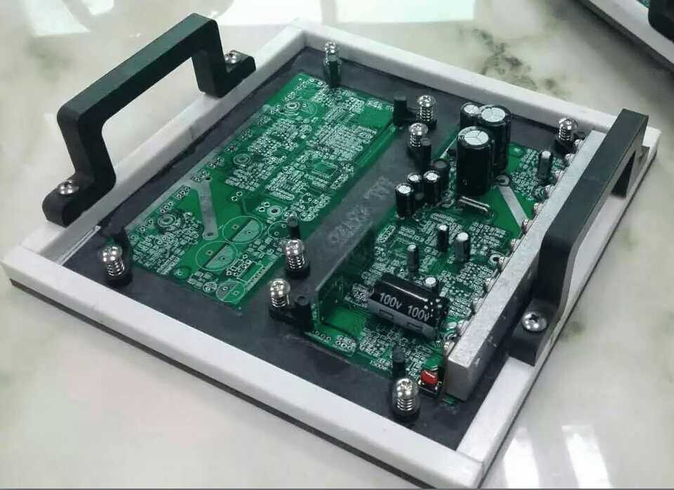
Electronic Manufacturing THT component Clinch Tooling to SMT Clearance (Bottom side)

All PCBs will be designed with the following preference guidelines for choice of components, placement, and track size. This strategy is intended to make maximum use of Design and Manufacturing capabilities and to minimize overall manufacturing costs:

  1. Full SMT. Component side only
  2. Full SMT. on both Component and solder sides
  3. Mixed SMT. and pth. on component side only
  4. mixed smt. and pth. with active smds on the component side and passive components on solder side

Clinch Tooling to SMT Clearance (Bottom side)

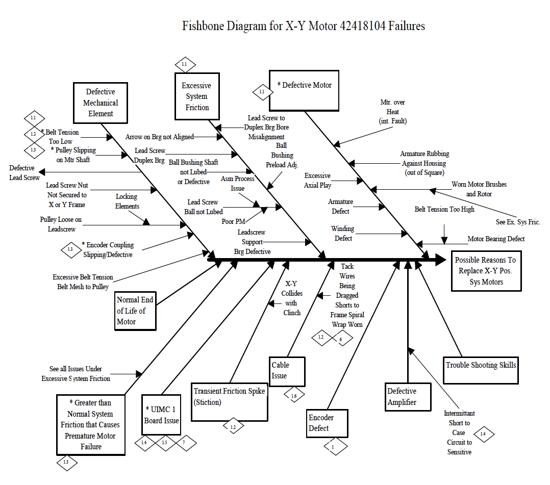
Universal Auto insertion machine X Y motor – U12DNUA/S6T,42418104

BrushedMotorX-YPositioningSystemMotionFaultDiagnosticProcedure

The following procedure is intended to be used as a diagnostic tool for determining general causes for X Y Positioning System Motor failures and Motion Faults. Using a known good motor, an attempt will be made to isolate the problem between there motor, or the other system issues. UsethisprocedureonlyonGeneration8,SingleHeadMachinesequippedwithBrushedMotors(referencepartnumber42418104).

Note:
Ifyouhavetoreplacea Motor, pleasereturnittoBinghamtonintheboxthereplacementcomesin.

EQUIPMENT NEEDED:
Good Motor, Blue Kendall grease (40833810) for leadscrew, 10W (40833827) oil for ball bushings & axis shafts, Phillips head screw driver, Allen wrenches

F/E SKILLS REQUIRED:

IM Diagnostics
X-Y Home Zero Set-up
Installing X-Y Positioning system motors

ESTIMATED TIME TO PERFORM PROCEDURE:
30 minutes if no problems found
3 hours if motor is found to be defective
5 + hours if other system problems are found INFORMATION (please fill out)

STEP1(PerformonXaxisfirst,thenrepeatonYaxis)

In this step, you will be running a single axis at reduced speed & acceleration while observing the Max DAC output, which is proportional to the torque. If the torque is too high, this may indicate motor or positioning system problems.

LAUNCH IM DIAGNOSTICS

Run “Quick Start” Select #1 “Set-up BEC”
When macro is done zeroing (quit don’t save) to exit “set-up BEC” screen

Select: DIAGNOSTICS, MANUAL DIAGNOSTICS
On the LEFT side, click the pull down menu of the “SECTION” box. Select “UIMC 1 AXIS INPUTS”
Click the BLUE “MOVE” button & edit the following parameters: Speed from 116 to 10
Acceleration from 2400 to 500

Click the Auto Cycle & Continuous Run check boxes Cycle the axis from 0” to 18” or 0 count to 144,000 count
Observe the “Maximum DAC Output During Move” number for approximately 5 minutes and fill out the STEP 1 CHART below.
If the number ever gets above 340 maximum, the system has too much friction. It could be the motor or other system problems.
If the “Maximum DAC output during move” is less than 340. Stop. No further steps are required for this Axis.
This Axis appears to be functioning correctly.

STEP1CHART
Proceed to STEP 2
STEP 2
In this step you will perform specific PM activities that have a large impact on the amount of torque required to
operate the positioning system.

Grease the lead screw, oil the shafts & re-tension the belt.

Cycle at normal speed and acceleration for ½ hour, check the appropriate box below.

Speed…………116 Acceleration….2400

Was theleadscrewdry? YESĀ NOĀ
Was theShaftdry? YESĀ NOĀ
Was thebeltloose? YESĀ NOĀ

Cycle at the reduced Speed & Acceleration per STEP 1 and fill out the STEP 2 CHART below. If it gets considerably better (Max DAC below 340) you’re done. If not, go on to STEP 3.

STEP2CHART

STEP 3

In this step you are removing the motor in preparation for Step 4 and making further investigation into possible sources of high positioning system friction.

Remove the motor and move axis by hand.
Feel and listen for binds, hesitations or noises in the lead screw and/or ball bearing/shafts.

Whatwasfound?

Check axial play/gap in the lead screw by grabbing it by hand & pushing in both directions. There should be no perceivable axial play in the leadscrew.

MaxDACOutputDuringMove

MaxDACOutputDuringMove

Was thereanyplay? YESĀ NOĀ
Replace any parts that you think it has problem.
Whatwasreplaced?
PartNo Description Symptom

Universal Auto Insertion machine X, Y Motor Maintenance Procedure

Purpose:

The purpose of this document is to describe how to maintain the “Gold” series motors, PMI type U12M4, and U12M4H (UIC part number 11467000, 13570000, 40051001, and 40051002, sold before November 1995) This procedure should be performed every six months, or more frequently if found to be necessary.

Tools Required:

Allen wrenches
Screw driver (5 to 6 mm wide)
Screw driver, small blade (2,5 to 3 mm wide)
Adjustable wrench

Prerequisite:

Push in the machine’s Emergency Stop button
Turn off the machine’s power

Procedure:

1. Note which wires are attached to which motor terminal. Using an adjustable wrench, remove the wires from the motor’s terminals.

2. Remove the motor from the machine

3. Remove the brushes from the motor

4. The minimum usable length of the carbon part of the brushes is .240 inches ( 6,1 mm) long. If the brushes wear shorter than .240 inches, the motor’s commutator wires can be damaged by electrical arcing.

So that the brushes will not wear to less than .240 inches, we recommend that they be replaced when they become .300 inches long ( 7,62mm). Universal’s part number for a set of four (4) brushes for these motors is B26100021.

5. Check that the motor’s shaft turns smoothly. If not, then the bearings are damaged, and the motor should be discarded.

6. Using clean, dry, compressed air, blow the carbon dust out of the motor.

7. Look through the brush holes and examine the condition of the commutator wires, while turning the motor ambien shaft. If there are any burned or damaged wires, the motor must be discarded.

8. To install the brushes into the motor, place the carbon block in the brush hole.

9. Using a small screwdriver, gently push the spring down into the brush hole. It will be necessary to reposition the blade of the screw driver several times into the coils of the spring, to make the spring go into the hole.

10. It may be necessary to push the metal tab on the side of the brush contact to make it go into the brush hole.

11. After the metal tabs have gone into the hole, use the screw driver to hold the brush contact down in the brush hole.

12. Pull the small screw driver blade out while moving the screw into place. Be sure that the brush contact’s tabs do not come completely out of the brush hole when doing this. Start the screw in the threaded hole by turning it clockwise with your fingers. If it will not turn easily, remove it, and repeat step 11. Then tighten the screw gently using the large screw driver.

13. Install all (4) brushes into the motor. Mount the motor on the machine again. Reattach the wires on to the proper motor terminals.
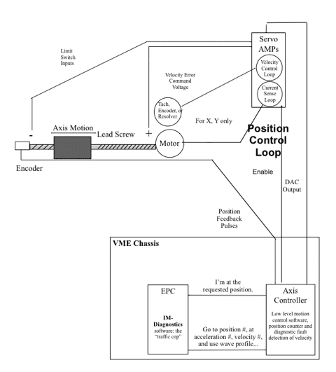
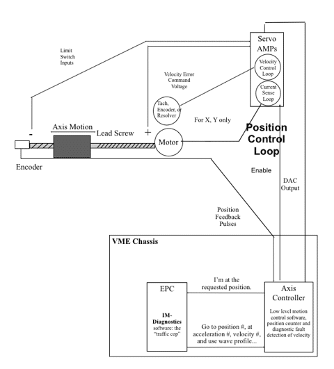
Machine Axis Control IM-Diagnostics Mode Overview *

*This is a generic overview for training purposes. Actual axes on the machine may differ slightly from this overview.

Universal Auto Insertion machine X, Y Motor Maintenance Procedure

Purpose:

The purpose of this document is to describe how to maintain the “Gold” series motors, PMI type U12M4, and U12M4H (UIC part number 11467000, 13570000, 40051001, and 40051002, sold before November 1995) This procedure should be performed every six months, or more frequently if found to be necessary.

Tools Required:

Allen wrenches
Screw driver (5 to 6 mm wide)
Screw driver, small blade (2,5 to 3 mm wide)
Adjustable wrench

Prerequisite:

Push in the machine’s Emergency Stop button
Turn off the machine’s power

Procedure:

1. Note which wires are attached to which motor terminal. Using an adjustable wrench, remove the wires from the motor’s terminals.

2. Remove the motor from the machine

3. Remove the brushes from the motor

4. The minimum usable length of the carbon part of the brushes is .240 inches ( 6,1 mm) long. If the brushes wear shorter than .240 inches, the motor’s commutator wires can be damaged by electrical arcing.

So that the brushes will not wear to less than .240 inches, we recommend that they be replaced when they become .300 inches long ( 7,62mm). Universal’s part number for a set of four (4) brushes for these motors is B26100021.

5. Check that the motor’s shaft turns smoothly. If not, then the bearings are damaged, and the motor should be discarded.

6. Using clean, dry, compressed air, blow the carbon dust out of the motor.
7. Look through the brush holes and examine the condition of the commutator wires, while turning the motor shaft. If there are any burned or damaged wires, the motor must be discarded.
8. To install the brushes into the motor, place the carbon block in the brush hole.

9. Using a small screwdriver, gently push the spring down into the brush hole. It will be necessary to reposition the blade of the screw driver several times into the coils of the spring, to make the spring go into the hole.

10. It may be necessary to push the metal tab on the side of the brush contact to make it go into the brush hole.

11. After the metal tabs have gone into the hole, use the screw driver to hold the brush contact down in the brush hole.

12. Pull the small screw driver blade out while moving the screw into place. Be sure that the brush contact’s tabs do not come completely out of the brush hole when doing this. Start the screw in the threaded hole by turning it clockwise with your fingers. If it will not turn easily, remove it, and repeat step 11. Then tighten the screw gently using the large screw driver.

13. Install all (4) brushes into the motor. Mount the motor on the machine again. Reattach the wires on to the proper motor terminals.

Machine Axis Control IM-Diagnostics Mode Overview *

*This is a generic overview for training purposes. Actual axes on the machine may differ slightly from this overview.