PC Board Handling Improvements in AI Equipment and Machines

PC Board Handling

Improvements in AI Equipment and Machines

Improve ROI with fast tracking your https://finasteridehair.com current Universal Insertion Machine to an Automatic Board Handling System

Upgrade Universal stand alone auto insertion machine to Automatic Board Handling System

Stay ahead of PCB Manufacturing! The digital curve is constantly bending toward demands for digital devices with increased capabilities and FASTER availability. By using the equipment you already own, you can improve upon its capabilities to meet these growing demands. We will use your current Universal Insertion Machine’s capabilities to transition it to an Automatic Board Handling System that will speed up processes and accomplish maximum PCB production successfully.

We at Southern Machinery have the solution to your distinct Automatic Board Handling needs. Whether you require Magazine-to-Magazine Configuration, Destacker/Conveyor-to-Magazine Loader Configuration, or In-line Configuration, we can serve to improve your PCB assembly line.

Upgrade Universal stand alone auto insertion machine to Automatic Board Handling System

Upgrade Universal stand alone auto insertion machine to Automatic Board Handling System

Ensuring the Best Design for Final PCB Production Stage with Testing!

Ensuring the Best Design for Final PCB Production Stage with Testing! Ensuring the Best Design for Final PCB Production Stage with Testing!

Avoiding Design Mistakes with Testing

Improve EMS Productivity by Testing Early

http://www.smthelp.net/product/high-speed-in-line-circuit-board-test-machine/

PC Board errors are a drain to EMS productivity. Through analysis and testing PCBs in the pilot stages, a smoother and more educated production set-up can be achieved. By performing automatic impedance measurements and testing of components (chip resistors and capacitors) early on, you can ensure the best design for production.

We recommend applying the best design logics when creating your PCB layout and Test, Test, Test for maximum efficiency and output. According to Circuits Assembly’s December 2016 Magazine, here is the list of 5 Most Common PCB Design Mistakes: “1. The components do not suit the production technology 2. Thermal imbalance 3. Incompatibility between fabrication and assembly technology 4. Component placement at PCB edge 5. Placing fiducials on the PCB’s edge.”

Once you have planned your PC Board with best practices, Southern Machinery’s High-Speed In-line Circuit Board Test Machine will help with testing by incorporating a visual inspection function which allows mounting status checks on each component (e.g.: typo descriptions in alphanumeric characters, orientation, size) on the operator’s monitor will serve to best analyze testing up close. As well as automatically generating test data from mounting data and component list.  

http://image.slidesharecdn.com/highspeedin-linecircuitboardtestmachine-fai-161223080028/95/high-speed-in-line-circuit-board-test-machinefai-14-638.jpg?cb=1482480094

http://image.slidesharecdn.com/highspeedin-linecircuitboardtestmachine-fai-161223080028/95/high-speed-in-line-circuit-board-test-machinefai-3-1024.jpg?cb=1482480094

http://www.smthelp.net/product/high-speed-in-line-circuit-board-test-machine/

SMT,PEC,UIC,Camera,Balser

UIC SMT machine PEC Camera Assembly – T50319001 Rev

Beam 2 FW PEC Camera Assembly – T50319001 Rev. K
This Document Supports Assembly 50319001 Rev. G


Replace the PEC Camera Assembly

If the PEC Camera Assembly is damaged or experiences an electrical or optical failure, the camera must be replaced.

CAUTION
Use caution when handling the PEC Camera and Lighting Assemblies. These assemblies are very sensitive to sudden shock. Also use ESD precautionary measures when handling the PEC Camera and Lighting Assemblies. A properly grounded ESD wrist strap is recommended.

Prerequisites

Make sure that the following items are available before beginning the procedure:

  • A new PEC Camera Assembly
  • A calibration kit and a new PEC gray card

Remove the PEC Camera Assembly

To remove the faulty PEC Camera Assembly from the head cage, perform the following procedure:

  1. Power down the machine and perform Lockout/Tagout according to local procedures.

WARNING – LOCKOUT/TAGOUT
The machine must be powered down and your site’s Lockout/Tagout procedure executed during this procedure to ensure personal safety.
  1. Open the access cover.
  2. Move the beam to a location where the PEC camera can be easily accessed.
  3. Disconnect the PEC_VIDEO/PWRPL and PEC_LED_CTRPL cables from the Head Cage Interface PCA.
  4. Remove all cable ties securing the PEC camera cables to the head cage.
  5. Remove the PEC camera cables from the cable clamps on the bottom of the head cage.
  6. Remove the screws that secure the PEC lighting to the PEC camera. Let the lighting hang loose from the hole in the carriage plate.

  7. Disconnect the PEC lighting cable from the PEC lighting. Set aside the PEC lighting.
  8. Remove the screws that secure the PEC camera to the carriage plate.
  9. Lift the PEC camera out of the head cage and discard.


Remove/Install the PEC Camera Assembly

If the PEC Camera Assembly is damaged or experiences an electrical or optical failure, the camera must be replaced.

CAUTION
Use caution when handling the PEC Camera and Lighting Assemblies. These assemblies are very sensitive to sudden shock. Also use ESD precautionary measures when handling the PEC Camera and Lighting Assemblies. A properly grounded ESD wrist strap is recommended.

Prerequisites

Make sure that the following items are available before beginning the procedure:

  • A new PEC Camera Assembly
  • A calibration kit and a clean, undamaged PEC gray card

Remove the PEC Camera Assembly

To remove the faulty PEC Camera Assembly from the head cage, perform the following procedure:

  1. Power down the machine and perform Lockout/Tagout according to local procedures.

WARNING – LOCKOUT/TAGOUT
The machine must be powered down and your site’s Lockout/Tagout procedure executed during this procedure to ensure personal safety.
  1. Open the access cover.
  2. Move the beam to a location where the PEC camera can be easily accessed.
  3. Disconnect the camera control/interface cables from the Head Cage Interface PCA.
  4. Remove all cable ties securing the PEC camera cables to the head cage.
  5. Remove the PEC camera cables from the cable clamps on the bottom of the head cage.
  6. Remove the screws that secure the PEC lighting to the PEC camera. Let the lighting hang loose from the hole in the carriage plate.

    (Typical PEC Camera and old-style mount shown below)
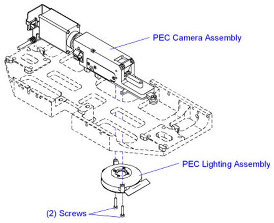

    (New-style PEC mount shown below)


  7. Disconnect the PEC lighting cable from the PEC lighting. Set aside the PEC lighting.
  8. Remove the screws that secure the PEC camera to the carriage plate or mounting block.
  9. Carefully remove the PEC from the head cage.
  10. If installing a camera with a different magnification, remove the 6 frame fiducial inserts on the feeder uprights and the 4 nozzle changer fiducials on the nozzle changer. Retain for use with the .4 MPP PEC camera.

    For UPS+ 7.5SC and higher with a .4 MPP PEC camera: Remove the 6 frame fiducial inserts on the feeder uprights; they will not be re-installed.

Install the PEC Camera Assembly

To install the PEC Camera Assembly, perform the following procedure:

  1. Carefully move the PEC camera into the head cage and position on the alignment pins.
  2. Apply Loctite 222 to the PEC camera mounting screws.
  3. Install the PEC camera mounting screws and torque to 1,36 Nm (12.0 in-lb.).
  4. Connect the PEC lighting cable to the PEC lighting.
  5. Install the PEC lighting to the new PEC camera and secure with the screws removed earlier.
  6. Route the PEC cables through the cable clamps on the bottom of the head cage.
  7. Connect the camera control/interface cables to the Head Cage Interface PCA.
  8. Install new cable ties to secure the PEC cables to the head cage. Do not over-tighten the cable ties.
  9. If installing a .4 MPP PEC camera where one did not exist previously, install the 6 frame fiducial inserts on the feeder uprights and the 4 nozzle changer fiducials on the nozzle changer. Install over the existing fiducials.

    For UPS+ 7.5SC and higher with a .4 MPP PEC camera:  Do not install the 6 frame fiducial inserts on the feeder uprights.

  10. Close the access cover.
  11. Power up the machine.
  12. Determine if the machine is equipped with the Cognex Vision system:
    1. Open Diagnostics II.
    2. Select Version Information > Hardware Options > Vision Systems.

If Cognex Vision is…

Then…

On the machine Continue with the next step.
Not on the machine Do the following:

  1. Update the camera drivers. For instructions, see the Update the Camera Drivers help topic in Voyager.
  2. Continue with the next step after the drivers are updated.
  1. Calibrate the PEC camera and lighting. For instructions, see the PEC Calibration: Camera and Lighting (Multifunction Machines) help topic in Voyager.

PEC Camera Polarizing Components

The PEC camera consists of two elements: a rotating polarizer that covers four of the eight illumination petals and a sliding polarizer. The sliding polarizer is located in the camera aperture. The axis of this polarizer, frequently referred to as the “analyzer”, is orthogonal to that of the rotating polarizer. The combination of these polarizers on the module results in cross-polarized illumination.


(Typical PEC Camera shown)

The rotating polarizer ensures that the substrate is illuminated with linear polarized light. The metal features and ceramic background reflect polarized light differently. The light reflected from the metal has no net change in polarization. Because the orientation of the sliding polarizer located in the camera aperture is orthogonal to that of the rotating polarizer, most of the light reflected from metal features is blocked. Therefore, metal features appear dark on the camera.

In contrast, the ceramic surrounding the metal features randomizes the polarization upon reflection. Because the polarization is randomized, a portion of the reflected light can pass through the central polarizer and reach the camera. Therefore, the ceramic background appears as a shade of gray.

The following table summarizes the polarization effects on metals and ceramics:

Material

Incident Polarization

Reflected Polarization

Central Polarizer Orientation

Intensity at Camera

Metal

Ceramic

Polarized Lighting Zones

The PEC Lighting Assembly has two lighting zones. Which zones are used for imaging depends on the type of substrate being imaged. The two lighting zones are shown in the table below.

Lighting Zone

LED Color

Graphic

Zone I

Blue

Zone II

Red

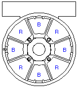
Petal Zones I and II each contain four illumination petals positioned at 90 degrees to each other. The illustration below shows how the Red (R) and Blue (B) LEDs are oriented.

Selectable Polarizer Positions

The PEC Lighting Assembly is equipped with a rotating polarizing filter and high intensity LEDs. The PEC camera has a polarizing film mounted within a rotating ring and a second polarizer mounted on a slide above the lighting module. Certain classes of flexible circuits image well with cross-polarized illumination. For the polarized option, it is recommended that the central polarizer be left in place.

  • The blue lighting zone of the PEC Lighting Assembly is designed to image flexible circuits.
  • The red lighting zone of the PEC Lighting Assembly is designed to image ceramic circuits.

The following table summarizes the available Polarized lighting options:

Lighting Zone

Graphic

Function

Zone I

Orienting the rotating polarizer above the blue LEDs allows non-polarized illumination from the Red LEDs. This lighting type is effective on dark-colored ceramics.

Zone II

Orienting the rotating polarizer located above the red LEDs allows polarized illumination from the Red LEDs. This lighting type is effective on white or light-colored ceramics.


AI, Auto Insertion : Axial Inserter; Radial Inserter; JW (Jumper Wire) Inserter; Odd form Inserter; PIN inserter; Eyelet Inserter; Terminal Inserter IM, Insertion Mount, MI,Manual Insertion, DIP, Wave soldering 5, SMT - Souface Mount Technology: BHS: PCB board handling system, Loader, Unloader, Conveyor,Shuttle Printer: Solder paste screen printer SPI: Solder Paste Inspection Mounter: Chip Mounter, Pick and Place, IC Mounter, High Speed Mounter AOI Reflow Oven

How to use Solder Preforms to improve your Electronic Product Quality


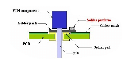
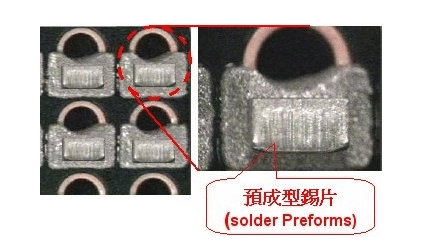
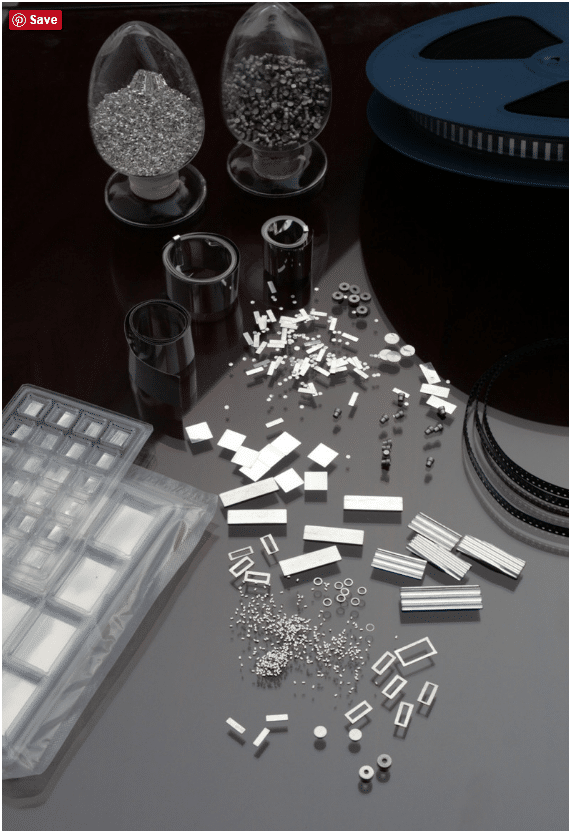
Solder Preforms are used in a variety of applications that require precise amounts of solder. Preforms come in standard shapes such as squares, rectangles, washers and discs. Typical sizes range from .010″ (.254mm) up to 2″ (50.8mm). Smaller and larger sizes, as well as custom shapes, are also available. Dimensions can be held to tight tolerances to assure volume accuracy.


  • Increased solder volume
  • Improved drop test results
  • Fewer issues with flux residue
  • Reduced rework
  • Improved fillet shape and volume


Optimal SMT stencil cleaning performance to improve Electronic Product Quality

Advantages of (2)

Powerful Cleaning Capability

Two ultrasonic cleansing head panels clear each the back and front sides of the metallic stencil concurrently. Ultrasonic power is utilized on to the stencil offering superior cleansing functionality.

Ease of Operation

Just press the beginning button and the method of cleansing and drying might be accomplished. No operator dealing with is required.

Low-VOC Cleaning Agent

Low-VOC cleansing agent, VIGON SC200 can be utilized for SC-AH100F-LV. There is not any flash level, low evaporation and virtually no odor. A good working setting might be maintained.

Reduction of CO2 Emission

reduces power consumption because of the shortened tact time and accordingly reduces CO2 emissions.

Cleaning Evaluation


Advantages of (2)
Powerful cialis Cleaning Capability

Two ultrasonic cleansing head panels clear each the back and front sides of the metallic stencil concurrently. Ultrasonic power is utilized on to the stencil offering superior cleansing functionality.

Ease of Operation
Just press the beginning button and the method of cleansing and drying might be accomplished. No operator dealing with is required.

Low-VOC Cleaning Agent
Low-VOC cleansing agent, VIGON SC200 can be utilized for SC-AH100F-LV. There is not any flash level, low evaporation and virtually no odor. A good working setting might be maintained.

Reduction of CO2 Emission
reduces power consumption because of the shortened tact time and accordingly reduces CO2 emissions.

Cleaning Evaluation

Who is one of the SMT solution provider for Global customers


initpintu_副本


Who is one of the SMT solution provider for Global customers, we can supply Automatic Insertion machines spare parts, SMT spare parts, (including feeder ,Nozzle,PCB board,feeder parts,motor,laser,feeder bank,feeder calibration jig ,ect)

main Service:

* Supply SMT/ AI spare parts.

* Supply SMT relate equipment.

* Supply SMT ancillary products and tools.

* Repair Service.

Contact me for more details:

Tel/WhatsAPP:(+86) 17773027293

Email: jessica@smthelp.net ;

Skype: Jessica SMT Sales


Odd-form component mounter

Odd-form component mounter
Improve product quality and increase production capacity solution.

odd-form solutions are designed for high volume and high mix production. Odd-form process automation is an efficient way to improve profitability significantly by increasing the throughput and assembly quality.
The benefits can be measured in assembly reliability, accuracy and flexibility, labor savings, assembly yield improvements, floor space savings and optimization of processes.

What is the NEXT of Through Hole Technology in Electronic Manufacturing


We designed and manufactured Auto Insertion machine in Shenzhen China,  -- Decreasing labor cost  -- Easier manufacturing and operations management  -- Predictable Product Quality – Less repairs  -- No wrong parts nor wrong polarity  -- Less risk of damage due to human contact (contamination, ESD, physical damage to components)  -- Better clinching, less risk of solder issues.  -- Smaller factory space required to produce same volume of product

Welcome to visit Through Hole Technology Channel: https://www.youtube.com/channel/UCXvX1BREsZIKMSFBXKVGCCg

Carrier clips — UIC Spare parts for Auto Insertion Machine

Carrier Clip is the very common wearing parts in Radial insertion machine. We manufacture the high copy spare parts , promise the quality and keep low cost .

Helps the Environment — S1688 stencil cleaner machine

Waste Streams from Printed Circuit Board Manufacturing
Waste Stream Waste Stream
Waste Source Description Composition
Cleaning/Surface preparation 1. Airborne particulates
2. Acid fumes/organic vapors
3. Spent acid/alkaline solution
4. Spent halogenated solvents
5. Waste rinse water
Catalyst application/
Electroless plating
1. Spent electroless copper bath
2. Spent catalyst solution
3. Spent acid solution
4. Waste rinse water
Pattern printing/masking 1. Spent developing solution
2. Spent resist removal solution
3. Spent acid solution
4. Waste rinse water
Electroplating 1. Spent plating bath
2. Waste rinse water
Etching 1. Spent etchant
2. Waste rinse water
Board materials,
sanding materials,
metals, fluoride,
acids, halogenated
solvents, alkali.
Acids, stannic
oxide, palladium,
complexed metals,
chelating agents.
Vinyl polymers,
chlorinated
hydrocarbons, organic
solvents, alkali.
Copper, nickel, tin,
tin/lead, gold,
fluoride, cyanide, sulfate.
Ammonia, chromium,
copper, iron, acids.