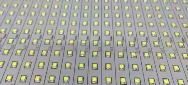
Southern Machinery provides professional SMT peripheral equipment

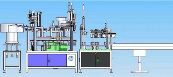

How to invest LCD TV Final Assembly factory
Volume Requirements
- Total estimated time to complete weekly- production volumes with proposed equipment set = 160 hours/per week (+/- 10%)
Notes:
- Available time is 80 hours (16hours x 5days)!
- Factory efficiency not optimum due to:
- Weekly Scheduling
- Bottle Neck is SM Lines (Top/Bottom)
- Occupation of Lines, High Volume PC’s
- For schedule improvements we propose:
- To add and reconfigure SMT lines, create dedicated HV PC & PC Monitor SM lines
- Increase inventory, make longer runs, increase weekly batches, warming up Factory
IM Lines

- Number of Lines : 3
- Machine Set: Radial S-3000 x 3, Axial S-4000 x 3
- Cycle time: Average 15 seconds
- Intrinsic Availability: 90%
- Mean Time To Repair: 120 seconds
SM Lines
- Number of Lines : 4
- Machine Set: High Speed Chip mounter x 2, IC mounter x 1
- Cycle time: between 12.60 & 25.29 seconds
- Intrinsic Availability: 90%
- Mean Time To Repair: 120 seconds

MI Lines
- Number of Lines : 4
- Machine Set:
- 10 x Assembly stations,each line
- Delta 5 Wave Solder, each line
- 4 x Test & Inspect stations, each line
- Average Cycle Time: 25 seconds

LCD TV FA Lines
- Number of Lines : 2
- Machine Set:
- 16 x Assembly stations
- 3 x L-Shape Soak System 30 min
- Simulation Soak is 30 min with 30 stations x 3
- Final QC/Test and Pack Out, 3 stations
- Two identical Lines (19” to 42”) for optimum Efficiency & Flexibility
- Average Cycle Time: 24 seconds/station


Why SMT? How to EMS?
Why SMT?
Manufacturers continuously evaluate new components and systems technologies in terms of reducing size, increasing design flexibility, improving reliability and reducing cost for systems. SMT satisfies all these requirements. It can provide size reductions of over 40%, assembly cost reductions of almost 50%, and can enhances the performance of electrical circuitry [Lea, 1988].
SMT Reduces Size and weight
The increased density of components can lead to a higher functionality in the same space. This allows the system manufacturer to price differentiate his product in the market by carefully choosing his components.
- SMT components require less circuit board area and volume than their through-hole equivalent.
- Components can be mounted on both sides of boards.
- Lighter components with the same functionality can be significant in the
aerospace industry as well as portable consumer electronics.
SMT Increases Performance
- SMT offers better interconnectivity due to shorter paths, providing lower inductance and capacitance.
- SMT reduces the package propagation delay, which is the time the signal needs to move from one component to another. Typically the longest delays in the system are off-chip.
- Electromagnetic interference can be decreased by combining sensitive circuits on a single board and improving its Electromagnetic Induction (EMI) shield design.
SMT Improves Reliability
- The smaller and lighter construction of SMC’s allow them to resist shock and vibration better than their through-hole counterparts.
- The reduced number of PCBs and connectors improves overall reliability at the system level.
- However, SMT systems require careful attention to mechanical design to avoid overstressing the solder joints.
- The demanding nature of the SMT process has resulted in extensive automation and corresponding increases in product quality.
-
SMT Reduces Cost
• Bare Boards
The use of SMT, typically, results in smaller area PCBs being used due to the reduction in the size of the components being used. In general for two functionally equivalent PCBs, one utilizing surface mount and the other using conventional through hole, the larger the PCB, the more expensive it will be. Increased density on an SMT board generally requires multiple layers as well as smaller line widths and spacings to accommodate the finer pitch components and smaller hole diameters to interconnect the layers. The only time a hole is required is to carry the signal to another layer whereas with through hole components there must be a hole for each lead of each component. In some cases through hole PCB’s may require more layers because there are more larger holes which means there will be less room on the inner layers for circuit routing increasing the layer count.• Processing
Surface mount components have almost all been designed for automatic assembly. Many unusually shaped, through-hole components, called odd- formed components, which were designed for hand assembly, can now be placed automatically as well. Automated assembly of surface mount assemblies can be done using one flexible automated placement machine whereas several machines may be required for the various through hole components.
As more types of components become available in a surface mount format, correspondingly fewer components are available in through-hole configuration forcing the cost of many SMC devices down. While through-hole components can be automatically inserted, the combined equipment, floor space and processing costs are higher.
• Factory Operating
Fewer types of assembly machines are required for an SMC assembly line and they often requires less floor space. Automated SMT assembly lines are considerably more productive than PTH assembly tools. Thus throughput is raised considerably with SMT manufacturing and the cost per unit of assembly is greatly reduced.
SMT Increases Flexibility
- SMT provides a wider range of packaging possibilities than insertion mount technology.
- SMT allows for the use of both surface mount and insertion mount devices in the same assembly.
SMT Eases Handling And Storage Space Needs
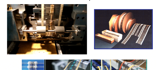
Surface mount components are easy to handle due to the various storage formats in which they are shipped and presented to the pick and place machines. Tape and reel, cartridge, sticks, magazines, and matrix trays allow effective and safe handling and shipping. The storage formats have the following features:
- Large number of components per packing unit resulting in less frequent loading of the tools.
- Small amount of packing materials per component resulting in lower shipping and inventory costs.
- Protection against transport and handling damage.
- Standardization, Definite orientation of the components.
- Protection against electrostatic discharge resulting in fewer defective systems
and rework.
- Compatible with highly automated equipment.
Electronic Industry Organizations and Groups
Uniform Standards for Surface Mount Technology are still under development in the USA, Europe and Japan. Although much has been accomplished, there is still no single set of industry guidelines. However, efforts are being taken to resolve this problem. For example, there was inconsistency in the standards set by the IPC and the EIA. As this was recognized, they have joined forces to set up a council called Surface Mount Council, to coordinate the various standards between the users and the developers of these standards. These documents have a J-STD- xxx designation. Moreover, other organizations like the International Microelectronics and Packaging Society (IMAPS) are working together on the technical issues in the PCB industry. These developments are promising and should lead to a common industrial standard in the near future.
IPC- Association Connecting Electronics Industries
2215 Sanders Road Northbrook, IL 60062-6135 USA Tel: (847) 509-9700 Fax – (847) 509-9798
Internet: www.ipc.orgIn 1999, IPC changed its name from Institute of Interconnecting and Packaging Electronic Circuits to IPC. The new name is accompanied with an identity statement, Association Connecting Electronics Industries.
IPC started in 1957 as the Institute for Printed Circuits. As more electronics assembly companies became involved with the association, the name was changed to the Institute for Interconnecting and Packaging Electronic Circuits. In the 1990s, most people in the industry could not remember the name and/or didn’t agree on what the words in the name meant. In addition, the leaders from government or other business groups could not understand the name either.
Get the Best in After-Sales Service
Our Process Today Matters
After-Sales Installation Service

Industrial IoT, exciting words that get thrown around in today’s EMS. While we are actively engaged with developing Smart Factories with embedded technologies, we know that today’s after-sales services are vital. Here’s a look at our process and how you can find confidence in our approach to After-Sales Services.
After Sales Service Plan:
- We arrange for your engineers to come to China and offer accommodationsincluding meals, and transportation while learning in our facilities.
- Installation – your equipment is delivered and installed by our engineers
- We then send our engineers to your home factory
- We recommend 7-15 days of Training and Production for full quality control
- Our Engineers are responsible for training your team and work with you to produce your products
- Follow-up – our team follows-up to ensure things are running smoothly

Our engineers are always here to make sure that your EMS Factory is always performing at top capacity. Here are some of the ways we ensure that you have everything you need to maintain top performing Equipment. We offer video trainings, Skype trainings, troubleshooting via Team Viewer, amongst other channels.
The future of After Installation Service with IoT:
With Industrial IoT, we look toward a future where all sensors will be extremely intelligent and collaborate to perform tasks via an entire network geared toward constant monitoring and improvement. Southern Machinery will continue to provide the customer service you are used to but will also have the capability to offer instant feedback with intelligent sensors that constantly read data and measure equipment output and quality. We look forward to this future with you.
[su_button url=”mailto: info@smthelp.net” background=”#00a3b3″ size=”5″]Service Questions HERE! [/su_button]
LED IoT Movement: How Smart Lighting is Brightening the Future & Your ROI
LED Smart Lighting.
Brightening the LED IoT Movement.

The LED IoT Smart Lighting market is projected to grow over 45% per year by 2020. This multi-billion dollar industry continues to create lighting for all markets meeting demands for efficiency, long lasting lights, and cost cutting on the manufacturing end.
Looking at how the market for the internet of things (IoT) is expanding and spreading into every industry, the notion that people can control https://zanaflexhome.com every light switch, electronic device or even plumbing fixtures while monitoring the energy usage of these items, are changing the lighting industry in monumental ways. LED is now a global movement and manufacturing companies are quickly advancing their machines to keep up with the great demand.

It is time to consider LED for your manufacturing…
[su_button url=”mailto: info@smthelp.net” background=”#00a3b3″ size=”5″]CLICK HERE for more HELP with Your LED IoT Future! [/su_button]
High Quality, Lower Cost SMT Factory
Smart SMT Factory

It is time to reexamine how you manufacture. Regardless of your industry, or the size, the opportunity to create a smart factory will no doubt decrease your costs and increase your profits. As technology advances, it is smarter to consider turning your aged model of outsourcing manual labor to a self-manufacturing model using surface mount and auto insertion technologies. If you can have the control of manufacturing your own unique products in-house, decreasing cost, time, and increasing your ROI, why wouldn’t you join the competition and reevaluate your current model?
Southern Machinery has over 20 years of experience, carefully designing buy prednisone your customized tailor-made SMT machines to fit your production. Investing in a customized SMT line for your manufacturing will set to improve your quality, productivity, and reliability.
What we provide:
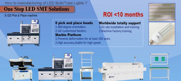
Full LED solutions tailored to your product
Core technology with our equipment
Highly skilled and professional tech service
Deep experience in LED factory setup
All Solutions to your LED Assembly for Quality and best ROI

Full SMT Line:
LED types: (LED blub, LED tube, LED strip, LED lens)
PCB size: 600mm, ~1200mm
Quantity: No command, start stage
SMT Line Design: Workers: 3-4 people (1 printer operator, 1 mounting operator, 1-2 Quality Control)
Capacity: 20000-22000pcs/hour (28000CPH FOR IPC9850)
Compressed air:6.0kgf/cm²
THT Thriving in Specialized Music Industry
THT Thriving in the Pro-Audio Industry
NAMM Show 2017

While in attendance at the 2017 National Association of Music Merchants (NAMM) Show last month we found one thing to be true… THT Equipment is far from dead. The music industry continues to require robust and durable components for high quality and heavy duty gear. GEAR, GEAR, GEAR! And the better the gear the more likely THT was involved in the assembly. Proving that THT is not just surviving but thriving in our high-tech world.
But there are many missing links! Many of these specialty components are still placed by hand and many more are still IMPORTED. Opportunities abound for manufacturers to bring all assembly, quality control, and profits back home. Quality is the name of the game when it comes to being #1 in any product category but costs sometimes hold back some manufacturers. According to Joel Menchey, Menchey Music Service, import costs for audio manufacturers are the highest of all costs. This doesn’t have to be so.
We at Southern Machinery have the solutions to lower costs and improve your manufacturing assembly quality! Our S-600-OF Through-hole & Surface Mounting Multifunction Machine paves the way to incorporate THT with SMT technologies. We can help you design the exact machine for your needs, ordered to spec. It’s a simple conversation for a huge shift in ideology and savings.
[su_button url=”mailto: info@smthelp.net” background=”#00a3b3″ size=”5″]CLICK HERE for more HELP with your THT Equipment![/su_button]

FEATURES:
- Six pick-up heads.
- Practical placement speed to 18,000 cph.
- Huge Component Range: places SMDs from 0402 to 15 mm x 15 mm, including resistors, capacitors, inductors, diodes/
audion , IC, SOTs, SOPs, QFPs and CSPs, and THT components. - Feeder racks can accommodate a mix of tape feeders and IC tube/stick feeders or 5 THT components feeder.
- Teaching/fiducial recognition camera for easy programming & operation
- Customized nozzles available.
- Bottom fixed-camera vision system for fast, accurate alignment.
- Ball screw drive and heavy-duty, uni-body construction ensure smooth, high-speed movement and high accuracy and repeatability.
- SMEMA-compatible inline
conveyor.
| SPECIFICATIONS:Placement Specifications | |
| Number of Placement Heads | 6 |
| Maximum Placement Speed | 25,000 cph |
| Average Practical Placement Speed | 18,000 cph |
| Placement Accuracy | ±0.05 (0.002″) |
| Minimum SMD Size | 1.02 mm × 0.51 mm (0.04 in × 0.02 in) |
| Maximum SMD Size | 15 mm × 15 mm × 10 mm (0.59” × 0.59” × 0.39“) |
| Alignment Method | Bottom vision standard |
| Capability for SMDs | LEDs, Resistors, Capacitors, Inductors, Diodes, Audion, |
| Transistors, SOTs, SOPs, QFP,s QFNs, CSPs | |
| Pick Up Specifications | |
| Negative Pressure Detection | Yes |
| Components Shortage Alarm | Yes |
| Board Handling Specifications | |
| Board Loading Method | Inline Conveyor |
| Maximum Board Length | 400 mm (31.5“) standard |
| Maximum Board Width | 360 mm (17.2“) |
| Minimum Board Length | 50 mm (1.97”) |
| Minimum Board Width | 50 mm (1.97”) |
| Board Thickness | 0.5 mm to 3.0 mm (0.02” to 0.12″) |
| Fiducial Recognition/ | Yes |
| Coordinate Correction | |
| Feeder Capacity | |
| Feeder Type | Pneumatic |
| Maximum No. of Feeder Ports | 30 Or 5 THT components Feeders. |
| Tape Feeder Sizes | 8, 12, 16 and 24 mm |
| Programming | |
| Operating System | Windows XP |
| PC, Keyboard, Mouse | Yes |
| Monitor | Flat LCD |
| Programming Camera | Yes |
| Numeric Data Entry | Yes |
| CSV Import | Yes |
| Step and Repeat for Matrix Boards | Yes |
| Mechanical Specifications | |
| X Axis Drive Mechanism | Ball Screw & Linear Guide Rail |
| X Axis Drive Motor | AC Servo |
| Y Axis Drive Mechanism | Ball Screw & Linear Guide Rail |
| Y Axis Drive Motor | AC Servo |
| Conveyor Drive Mechanism | Ball Screw & Linear Guide Rail |
| Conveyor Drive Motor | AC Servo |
| Transmission Drive Mechanism | Belt |
| Transmission Drive Motor | DC Stepper |
| Z Axis Drive Mechanism | Belt |
| Z Axis Drive Motor | DC Stepper |
| X-Y Axis Resolution | 0.005 mm (0.0002“) |
| Z Axis Resolution | 0.005 mm (0.0002“) |
| T Axis Range of Motion | 360° |
| Physical Specifications | |
| Overall Dimensions | 1300 mm x 1380 mm x 1410 mm (51.2” x 54.3” x 55.5“) |
| (L x W x H) | |
| Approximate Net Weight | 1000 Kg |
| Facility Requirements | |
| Standard Voltage | 220 V – Single Phase, 50Hz |
| Air Pressure | 0.6MPa (6.1kgf/cm2) |
| Service and Support | |
| Remote Diagnostics | On-line |
| Warranty | 1 Year |
