Dispenser for high precision products

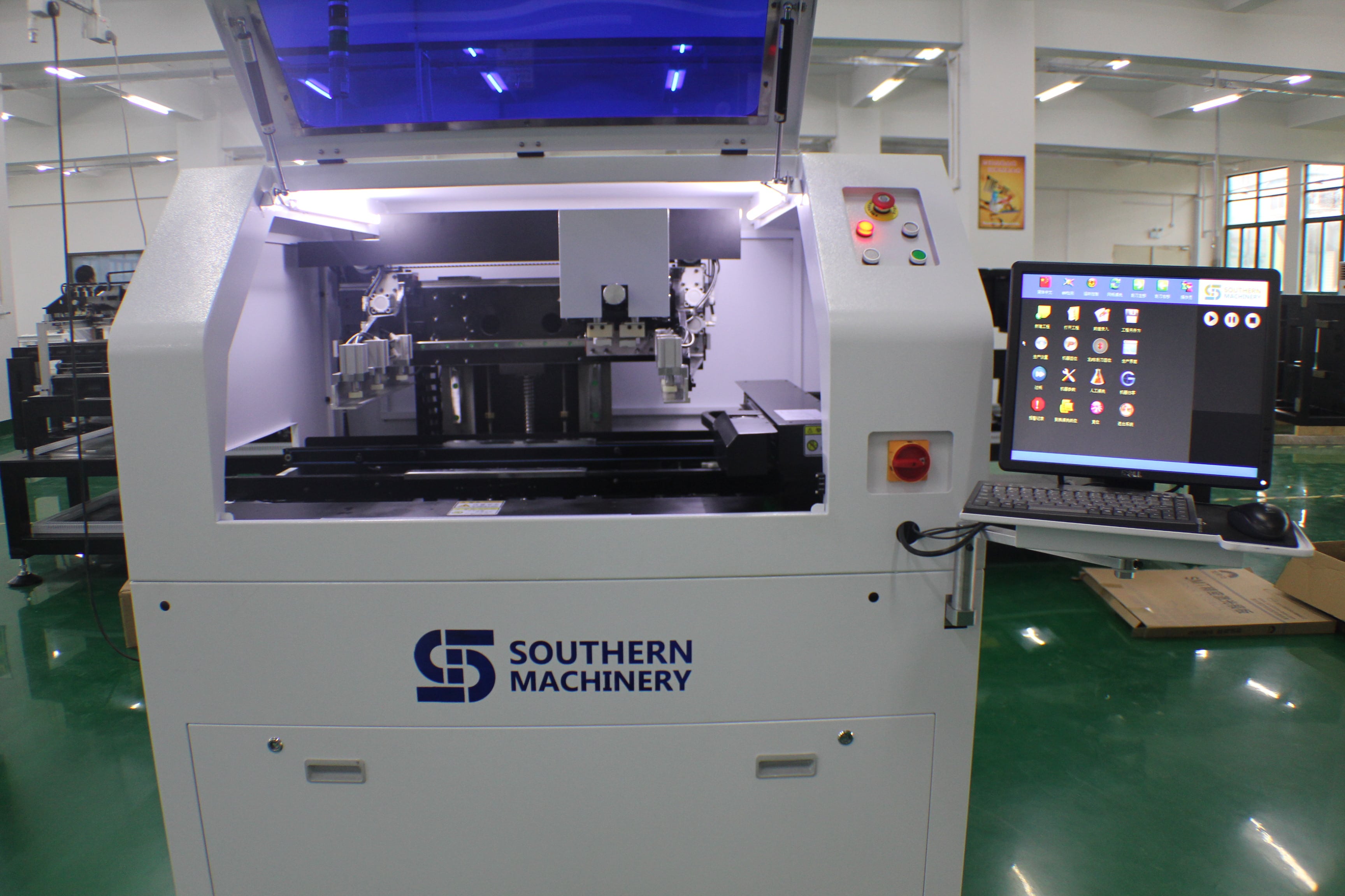
Fully automatic dispensing system bench top automatic visual glue dispenser  Automatic visual glue dispenser    is used to Chevrons,  fridge magnets, key chains,  power supply, cell phone,energy saving light, LED, DVD, DC, Switch, Connector, relay and other industries needing fluid glue solder.

Feature of  Glue dispensing equipment

1 Improve the production efficiency,reduce artifical loss.

2 Equipped with high performance CCD vision positioning system,visual dispensing route,improve accuracy.

3 Use industrial computer to control  operating system,

4 According to the different artifacts, choose suitable LED light source for lighting.

5 Adopt servo motor, ball screw drive.

6 It can arbitrary match with needle valve, diaphragm valve,screw valve, pnematic injection valve, piezoelectric injection valve.


Congratulation SOUTHERN MACHINERY has beed admitted as Foreign Member of ELCINA community

http://www.elcina.com

Electronic Industries Association of India identifies and bringstogetherlikeminded companies to represent the voice of Indian electronics and IT hardware industry and promote manufacturing.Electronic Industries Association of India promotes hardware manufacturing through active representation in the Government as well as scientific/technical institutions and industry/trade organisations in India and abroad.Electronic Industries Association of India represents to the government, problems faced by its members, individually or as a group, to find solutions and provide relief from unreasonable acts of administrative and policy making departments.

Electronic Industries Association of India provides a bouquet of professional and value-added services to its members. These services are tailored to serve the best interest of its Members and the Electronics/IT community to empower it to face competition and prosper. These services are constantly upgraded to suit the changing demands of the environment and needs of the industry.

Electronic Industries Association of India’s E-commerce facilities and its dynamic website together attract about 3500 visitors per day and provide a platform for members.

Electronic Industries Association of India is a repository of information and research, readily available for its members and helps them in taking critical decisions based on relevant facts.

Services currently provided by Electronic Industries Association of India to its members can be found by clicking here.

Grease / Oil for Electronic Manufacturing SMT machine

We provide a variety of Grease /  Oil for Electronic Manufacturing SMT machine

NSK Series lubricants


NSK NSL oil is linear guide for oil.

NSK PS2 is a high- precision high-speed grease lubricants . Use advanced synthetic base oils , urea thickener and special additives , has excellent corrosion resistance and abrasion resistance and long service life , suitable for high speed , the temperature, the use of small high-speed machinery , suitable temperature is 190 degrees.

nsknks66331428570405

NSK LG2 grease lubricants are dedicated clean room , pollution , specifically for semiconductors,

20141104102434_9888

LCD manufacturing equipment and food machinery.

NSK AS2 oil is heavy , waterproof anti- corrosion grease with precision .

PastedGraphic-9

NSK LR3 grease lubricant is high temperature and high precision .

 PastedGraphic-10

NSK GREASE NSL

Lubricants for linear guide for oil, mainly used in our industry Yamaha SMT machines, special screw on the Y -axis X -axis , because the parts at high speed while the ball requires a lot of lubrication, because this oil has excellent wear characteristics , can effectively inhibit the high-speed friction problem when used .

Packing : 80G / branch ;AI spare parts、Universal Parts,UIC,TDK.VCD Sequencer.SMT,THT,PCB,PCBA,AI,wave soldering,reflow oven,nozzle,feeder,wave soldering,PCB Assembly, LED, LED lamp, LED display

Manufacturer : NSK CO, LTD Seiko Corporation . .

Usage: can be used with Japanese NSK HGP oil gun to use , but also with THK MG70 grease guns , shaped nipple tubing complete SMT equipment maintenance refueling dedicated .



NSK GREASE PS2

● Features

The main component of the base oil used in synthetic and mineral oil , having excellent lubricating properties of the high-speed driving at a low temperature with a light load in terms of grease .

● Use it NSK miniature ball screw linear guide and standards adopted lubricant. Although it is very excellent driving characteristics of low-temperature lubricant , at room temperature, but also has good turning characteristics , it is very suitable for precision load small precision machine.

In our industry, mainly for the private placement on a Yamaha machine, low speed bearings and sliders, shortcomings , the temperature is not high , wear is not very good .

Packing : 80G / branch ;

Manufacturer : NSK CO, LTD Seiko Corporation . .

Usage: can be used with Japanese NSK HGP oil gun to use , but also with THK MG70 grease guns , shaped nipple tubing complete SMT equipment maintenance refuel special .


GREEN NS7

NSK GREASE NS7 lubricants, adapt the temperature from -40 ℃ to 140 ℃ to some extent can be used for a wide range of temperatures. The product is a low base oil viscosity , good lubricating properties.

Features:

A high durability and excellent performance, long-life grease

2 low-temperature performance and excellent mechanical properties at high speed during operation , some oil leakage.

3 .. low wear, at room temperature , in order to reduce bearing friction torque.


5 grease excellent performance can be maintained for a long period of time.

6 to have excellent water resistance .

(7) The effect of the product can reduce the brine excellent rust device

Which products for FUJI SMT , NXT and CP842 dedicated

Packing : 80G / branch ;

Manufacturer : NSK CO, LTD Seiko Corporation . .

Usage: can be used with Japanese NSK HGP oil gun to use , but also with THK MG70 grease guns , shaped nipple tubing complete SMT equipment maintenance refueling dedicated .

NSK LR3

● Features

     Refined mineral oil in the base oil, grease, and a lithium-based thickener additives of special abrasion resistance, excellent extreme pressure resistance of the pan with a large load with grease. It has the load resistance and excellent oxidation stability , maintain good lubrication performance for a long time , and with high lubrication life. Excellent water absorption , even in the state contains a lot of water under , it will not be washed away by the water softener .

● Use

     It is common grease NSK linear guide and ball screw standards adopted . Oil dynamic viscosity, excellent load resistance , oxidation stability is also very good , it can be widely used for various purposes , is a common type of grease used .

In our industry, mainly for Yamaha SMT machines, special bearing on l , paragraph grease lubricants are high temperature and high precision , large-scale metal processing machine tool spindle bearings specifically for high-speed , high-temperature , high load for the girth greater than 62MM high-speed bearings , which can effectively improve the machining accuracy and extend bearing life.

Packing : 80G / branch ;

Manufacturer : NSK CO, LTD Seiko Corporation . .

Usage: can be used with Japanese NSK HGP oil gun to use , but also with THK MG70 grease guns , shaped nipple tubing complete SMT equipment maintenance refueling dedicated .


NSK GREASE LG2 / NSK GREASE LG2 (Clean Room)

Features: The grease used as a clean room of the Department of straight rails and ball screws and other special grease , developed by NSK alone products, with the original clean room compared to the commonly used fluorinated grease , it has a high lubricity, lubricating long life, stable fat torque characteristics ( slip resistance ) , etc. , also have high rust resistance and dust characteristics , to achieve the same grease better than other low dust characteristics. Furthermore, not a special base oil used instead of mineral oil , the same method can be used ordinary lubricants.

Uses: For high cleanliness requirements of semiconductor , liquid crystal lubricant Linear Guides (LCD) manufacturing equipment , such as the use of a ball screw and rotating products. But the pressure of the grease dedicated clean environment , it can not be used in a vacuum environment .

 In our industry, mainly for Yamaha SMT , COB bonding machine.

Packing : 80G / branch ;

Manufacturer : NSK CO, LTD Seiko Corporation . .

Usage: can be used with Japanese NSK HGP oil gun to use , but also with THK MG70 grease guns , shaped nipple tubing complete SMT equipment maintenance refueling dedicated .


NSK GREASE AS2

One can withstand , with a gravity well.

Second, the continuing good , good adhesion, good adhesion .

Third, the product has a certain acidity , resistant to corrosion.

Fourth, a strong water resistance.

Disadvantages : The temperature is not good, poor wear resistance.

In our industry, mainly for Yamaha SMT machines , special placement head , because this part of the low-speed operation , while only need to play a minor slip can be lubricated . Packing : 80G / branch ;

Manufacturer : NSK CO, LTD Seiko Corporation . .

Usage: can be used with Japanese NSK HGP oil gun to use , but also with THK MG70 grease guns , shaped nipple tubing complete SMT equipment maintenance refueling dedicated .
AI, Auto Insertion : Axial Inserter; Radial Inserter; JW (Jumper Wire) Inserter; Odd form Inserter; PIN inserter; Eyelet Inserter; Terminal Inserter IM, Insertion Mount, MI,Manual Insertion, DIP, Wave soldering 5, SMT - Souface Mount Technology: BHS: PCB board handling system, Loader, Unloader, Conveyor,Shuttle Printer: Solder paste screen printer SPI: Solder Paste Inspection Mounter: Chip Mounter, Pick and Place, IC Mounter, High Speed Mounter AOI Reflow Oven

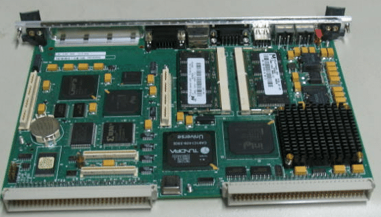
Auto Insertion machine CPU board EPC-1316 Boot Sector and BIOS Corruption Procedure for Re-flash

48797301 board
Procedure

Symptoms of corrupted BIOS and/or Boot Block:

  • No video signal from the EPC-1316
  • No activity on
  1. The keyboard, no status lights at power-on
  2. The floppy drive with a disk in or out
  3. The hard disk drive evident by the light off after a certain amount of time
  • The EPC-1316 is trying to access the CD-ROM drive with failed attempts every second or so.
  • The EPC-1316 is in this cycle indefinitely

Steps to take:

  1. Power down the EPC-1316 board/machine.
  2. Make sure that this instructions file is opened on a different computer.
  3. At the last step of these instructions is an embedded object of the .zip folder; it contains all of the files needed for this procedure.
  4. Right click on the .zip folder, select ‘Package Object’ and click on ‘Activate Contents’. If a message regarding a trustworthy source is displayed, confirm that this source can be trusted
  5. Create a new folder on the Desktop and rename it to “EPC-16FBD1.00.10”
  6. Click ‘File’, then select and click on ‘Extract All…’
  7. Extract the .zip folder into the folder on the Desktop, created in Step 3.
  8. Obtain a 3.5in Floppy Disk and insert it into the drive.
  9. Open the “EPC-16FBD1.00.10” folder from the Desktop
  10. To run an MS-DOS program, double click on the CRISDISK.BAT file.
  11. To run a Windows Application, double click on the WINCRIS.EXE file.
  12. Go through prompts of the program attentively; and a crisis disk will be created.
  13. Remove the EPC-16 board from the VME chassis/rack.
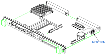
  14. At the bottom of the board there are 2 x 5 jumper pins: MFG/Flash. (Figure 1)


Figure 1 EPC-1316 Board jumper pin location

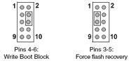
  1. See Figure 2 for PIN-out of the Jumper pins.


Figure 2 EPC-1316 Board jumper pin numbering

  1. Using 2 jumpers (Figure 3): place one to jumper pins 4-6. (jumper setting ‘Write Boot Block’)
  2. Place the second to jumper pins 3-5. (jumper setting ‘Force flash recovery’)


Figure 3 EPC-1316 Board flash jumpers configuration

  1. Replace the EPC-1316 board to the VME chassis/rack.
  2. Insert the 3.5in Floppy Disk that was created from the steps above into the floppy drive.
  3. Power-up the machine/chassis/EPC-1316.
  4. If the status light on the floppy drive comes on and stays on, then the floppy disk is being accessed.
  5. When the floppy drive stops accessing the Floppy Disk, wait about 5 seconds, and then remove the disk.
  6. Power down the EPC-1316, and remove it from the VME interface.
  7. Remove jumpers from the board and replace the board to the VME interface.
  8. Power-up the machine/chassis/EPC-1316 and make sure that it boots the operating system.
  9. Refer to UIC procedures for proper BIOS settings/ configuration


UIC, EPC-1316 Boot Sector and BIOS Corruption Procedure for Re-flash

Procedure

Symptoms of corrupted BIOS and/or Boot Block:

  • No video signal from the EPC-1316
  • No activity on
  1. The keyboard, no status lights at power-on
  2. The floppy drive with a disk in or out
  3. The hard disk drive evident by the light off after a certain amount of time
  • The EPC-1316 is trying to access the CD-ROM drive with failed attempts every second or so.
  • The EPC-1316 is in this cycle indefinitely

Steps to take:

    1. Power down the EPC-1316 board/machine.
    2. Make sure that this instructions file is opened on a different computer.
    3. At the last step of these instructions is an embedded object of the .zip folder; it contains all of the files needed for this procedure.
    4. Right click on the .zip folder, select ‘Package Object’ and click on ‘Activate Contents’.  If a message regarding a trustworthy source is displayed, confirm that this source can be trusted
    5. Create a new folder on the Desktop and rename it to “EPC-16FBD1.00.10”
    6. Click ‘File’, then select and click on ‘Extract All…’
    7. Extract the .zip folder into the folder on the Desktop, created in Step 3.
    8. Obtain a 3.5in Floppy Disk and insert it into the drive.
    9. Open the “EPC-16FBD1.00.10” folder from the Desktop
    10. To run an MS-DOS program, double click on the CRISDISK.BAT file.
    11. To run a Windows Application, double click on the WINCRIS.EXE file.
    12. Go through prompts of the program attentively; and a crisis disk will be created.
    13. Remove the EPC-16 board from the VME chassis/rack.
    14. At the bottom of the board there are 2 x 5 jumper pins: MFG/Flash. (Figure 1)

Figure 1 EPC-1316 Board jumper pin location

    1. See Figure 2 for PIN-out of the Jumper pins.


Figure 2 EPC-1316 Board jumper pin numbering

    1. Using 2 jumpers (Figure 3): place one to jumper pins 4-6. (jumper setting ‘Write Boot Block’)
    2. Place the second to jumper pins 3-5. (jumper setting ‘Force flash recovery’)

Figure 3 EPC-1316 Board flash jumpers configuration

    1. Replace the EPC-1316 board to the VME chassis/rack.
    2. Insert the 3.5in Floppy Disk that was created from the steps above into the floppy drive.
    3. Power-up the machine/chassis/EPC-1316.
    4. If the status light on the floppy drive comes on and stays on, then the floppy disk is being accessed.
    5. When the floppy drive stops accessing the Floppy Disk, wait about 5 seconds, and then remove the disk.
    6. Power down the EPC-1316, and remove it from the VME interface.
    7. Remove jumpers from the board and replace the board to the VME interface.
    8. Power-up the machine/chassis/EPC-1316 and make sure that it boots the operating system.
    9. Refer to UIC procedures for proper BIOS settings/ configuration


AI spare parts、Universal Parts,UIC,TDK.VCD Sequencer.SMT,THT,PCB,PCBA,AI,wave soldering,reflow oven,nozzle,feeder,wave soldering,PCB Assembly, LED, LED lamp, LED display

ETA and Southern Machinery will attend the USA IPC APEX EXPO 2016 exhibition

ETA and Southern Machinery will attend the USA IPC APEX EXPO 2016 exhibition to share the industry’s top feast.


You are warmly welcome to visit our booth No. :#2930 in USA IPC APEX EXPO (Mar. 15th-Mar17, 2016)

As the industry’s leading manufacturers, ETA would show our latest T-series lead-free reflow oven together with Southern Machinery in USA IPC APEX EXPO 2016 exhibition.This is unique machine in China now. It refreshes the traditional perception of reflow oven. T-series lead-free reflow oven could ensure the lead-free process optimization under the condition of the smallest footprint and the lowest power consumption. It could meet all customer’s demand. Meanwhile, Many new special equipment will also be displayed at this show.

ETA is the professional manufacturer of reflow oven and offer full SMT solutions for customers. We have more than 20 years experience and technology in SMT filed. The most professional term and the best service are waiting for you. Our goal is to provide the reliable full SMT solutions to all the customers around the world. Southern Machinery is our good global partner. We would provide the high-value technical support to our customers together.

www.smt11.com,

www.smthelp.net

You are warmly welcome to visit our booth No. :#2930.

AI spare parts、Universal Parts,UIC,TDK.VCD Sequencer.SMT,THT,PCB,PCBA,AI,wave soldering,reflow oven,nozzle,feeder,wave soldering,PCB Assembly, LED, LED lamp, LED display

AI spare parts、Universal Parts,UIC,TDK.VCD Sequencer.SMT,THT,PCB,PCBA,AI,wave soldering,reflow oven,nozzle,feeder,wave soldering,PCB Assembly, LED, LED lamp, LED display
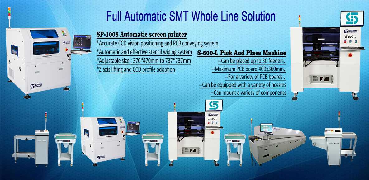
Southern Machinery:Provide SMT whole line solution.

Lead-free & Good quality & Cheap Solder Paste

Product Description

This solder paste special for SMT production process. It is made from the special solder paste and sphere tin power with little oxide content. It has the excellent performance in continuous printing. It has very little residue after reflow and very good insulation impedance. With various alloy composition, different diameter of tin powder, and metal content to meet the customer need in products and process requirement.

Product Feature and Selling points                                                                                                           

  1. 1.    Good http://shopantibioticsonline.com rollability in printing, excellent performance in printing even for 0.3mm part spacing in steel plate.
  2. 2.    Little changes for the viscosity for continuous printing, longer life time for the stencil, and good printing performance even for continuous 8 hours printing.
  3. 3.    No slump electron migration several hours after printing.
  4. 4.    Excellent welding performance and proper wettability in different parts.
  5. 5.    Adaptable to different level of welding equipments, finish welding with no nitrogenization, good performance in welding even in wide range reform temperature.
  6. 6.    Very little residue, light in color, and good insulation impedance and no corrosion to PCB, no need clean.
  7. 7.    Good testing performance in ICT.
  8. 8.    Workable for paste in Hole process
  9. Solder paste3 Solder paste6 Solder paste2 Solder paste1 Solder paste IMG_2792

PCBA Quality Process Audit — SMT Pick and Place machine

1. Work Instructions
1.1 Is there a revision controlled Operator Work Instruction which contains loading information for the specific product being built? (Score 0 if any unsigned/undated handwritten instructions or any handwritten instructions more than 48 hrs old)
1.2 Are Work Instructions readily available to the operator and are they followed at Component Placement?
1.3 Are component part numbers and descriptions included on the Work Instructions?
1.4 Are component descriptions sufficiently detailed to check at first-article that the correct components are being used?
1.5 Is the machine head/slot number for component loading specified for each part number on Work Instructions?
1.6 Are the reference designators and the quantity per part number specified on Work Instructions?
1.7 Is the component feeder type/size specified on Work Instructions or otherwise for each component package type?
1.8 Is the machine Program Name specified on the Work Instruction or line set-up instructions?
2. Component Loading and Verification
2.1 Is there an automated bar coded component loading verification aid in order to reduce the probability of incorrect loading? Note*
2.2 Are the component loading verification aids hard linked to the placement program so that loading is verified against program data?
2.3 Can traceability of component lot codes be demonstrated for critical devices?
2.4 Is component loading/changes verified and cross checked by an individual other than the set-up operator at product changeover? Note*
2.5 Is a component loading/changes verification log signed by the set-up operator and countersigned by the cross checker before start up? Note*
2.6 Is the correct feeder loading base used to facilitate real to feeder loading?
2.7 Are first-built boards verified against documentation for missing/misplaced components and for correct component polarity?
2.8 Are first-articles conducted using AOI methods and complemented with description verification and value metering?
2.9 Are all Resistors & Capacitors measured for a value within the tolerance (one per part number) at first-article & at reel change?
2.10 Is a first-article log signed to verify acceptance before start up?
2.11 Is the orientation of Tantalum SMT capacitors, Diodes, etc in tape format, standardized and documented for polarity orientation?
2.12 Is the IC tray loading polarity standardized for each type of polarity indicator that can be used for each component?
2.13 Is loading polarity referenced both from the tray and the component so as to ensure retrayed components are correctly loaded?
3. Nozzles, Feeders, and Tooling
3.1 Is there a document which details the standardized nozzle diameter set-up selected for each type of placement equipment?
3.2 Are these standardized nozzle diameter set-up documents readily available for when nozzles need to be replaced or changed?
3.3 Is there a document which details the range of component XYZ body sizes that each selected nozzle type can successfully place?
3.4 Is there a documented requirement to conduct daily nozzle centering and is there evidence that this is done?
3.5 Is each feeder identified with its own unique serial number?
3.6 Is there a documented and effective Feeder Maintenance Program? Records (s/w or otherwise) must be by Feeder Serial Number.
3.7 Are database records maintained for each feeder serial number for the purpose of tracking its maintenance history and performance?
3.8 Is feeder maintenance history used to monitor feeder life so that problematic feeders can be removed from the process?
3.9 Can it be demonstrated that the number of feeder indexes is counted & monitored for each unique feeder using software or otherwise?
3.10 Is this information used to flag that feeder preventative maintenance is required after x number of indexes?
3.11 Is there a documented requirement to indicate that Blocks or Support Pins are needed for specific products?
3.12 Is the No, location, type and height of Support Blocks/Pins identified on a product by product basis? Score NA if in 3.11 there are not needed.
3.13 Are the Support Pin locations identified for each product using templates/tooling or some other effective solution? Comment as above.
4. Moisture Sensitive Devices
4.1 Are components stored before loading and after unloading in a manner which prevents damage?
4.2 Are the Moisture Sensitive Devices (MSDs) and their sensitivity level readily known to the operator?
4.3 Are MSDs time stamped at opening and their exposure time monitored against pre determined limits?
4.4 Is there a flag to indicate that the exposure time has been exceed for any given device in a dry box?
4.5 Is there a flag to indicate the MSD exposure has expired for any MSD device currently loaded in the placement machines?
4.6 Have MSD procedures been updated to reflect the JEDEC standard for MSD control? (J-STD-033A MSD released in July 2002)
4.7 Is there evidence of correct implementation of J-STD-0033A for all MSD devices?
4.8 Are there MSD procedures in place to ensure MSD shelf life is reduced based on measured Relative Humidity conditions?
4.9 Is there a method in place to address the time spent in dry storage and its effect on remaining life based on MS Level and RH Level?
4.10 Is it clearly understood that MSD ‘shelf life’ continues to degrade during dry cabinet storage of some MSD devices?
4.11 If MSDs are on both sides of a PCBA, is there an effective method to account for time between 1st and 2nd reflow?
4.12 Can MSD control be demonstrated for MSD devices that need internal/external pre-programming?
4.13 Can MSD control be demonstrated for rejected devices and devices used for rework?
4.14 Have MSD recovery methods been defined and adequate for all component types?
4.15 Does the control of Moisture Sensitive Components include those components on reels?
4.16 Is the baking or hot room storage time and temperature documented and controlled for component recovery?
4.17 Has this time and temp been determined based on the component supplier’s guidelines / J-STD-0033A?
4.18 Is there evidence to demonstrate that the control process for MSDs is in use and is effective?
5. Machine Capability
5.1 Are Component Placement Programs generated from CAD XY coordinate data?
5.2 Is there a standardized nomenclature for Shape Code definition?
5.3 Can this nomenclature be used to determine the most appropriate shape code to allocate to a given part of given dimensions?
5.4 Are localized fiducials used for fine pitch devices when localized component fiducials exist on the board?
5.5 Has manual component moving been eliminated given correct CAD, nozzle set-up, Shape Code allocation, local fiducials, Cam speed, etc?
5.6 Does the Fine Pitch placement machine have the capability to check lead Coplanarity in xyz?
5.7 Does the Fine Pitch placement machine use its coplanarity capability on all leads of 20 mil pitch or less, and all programmed parts?
5.8 Does the Fine Pitch placement machine have the capability to check ball arrays? If no such device, score NA.
5.9 Does the Fine Pitch placement machine use its ball array verification capability for all BGA devices? If no such device, score NA.
5.10 Is the machine Program Name revision controlled to show traceability of program changes?
5.11 Is the machine Program Name traceable to the PWB and PCBA part number?
6. PCBA
6.1 Are outputted boards at least sample inspected pre reflow for placement positional accuracy for machine control purposes?
6.2 Is the frequency for this verification defined and documented, and is there evidence to suggest it is followed?
6.3 Is there a visual aid available which identifies the populated locations with polarity, and also the no-pop locations?
6.4 Is there a placement standard pre reflow to validate placement accuracy for the shape code, nozzle allocation, etc. parameters used?
6.5 Is there evidence to demonstrate that action is taken to adjust the machines performance for when this standard is exceeded?
7. Attrition Rates and Rejected Components
7.1 Is attrition rate monitoring conducted systematically to ensure feeder and/or nozzle problems are captured at least hourly?
7.2 Is there documented evidence to ensure attrition rates are checked and actioned at least hourly to ensure process control?
7.3 Is there a specification defined for acceptable attrition rates for the individual feeders?
7.4 Is there a specification defined for the maximum allowable number of nozzle skips per machine before it is shut down for repair?
7.5 Are these specifications determined based on a percentage combined with the number of placements for a given time period?
7.6 Is there evidence to demonstrate that attrition rate monitoring is conducted, effective, and used to make process control decisions?
7.7 Is there a documented process for the disposition or reuse of machine rejected components? Rs and Cs must not be reused even for rework.
7.8 Are rejected components reviewed and repaired to ensure conformance before reuse, even if only used for rework?
7.9 Are there repair blocks available or a lead conditioner in use for repairing ‘real’ Coplanarity rejects? Score 0 if parts not repaired.
7.10 Does the re-traying process always ensure that component polarity wrt the tray and the component loading polarity is preserved?
7.11 Is there a documented Process Deviation procedure to manage machine skips for hand placement if hand placement is allowed?
8. Process Capability
8.1 Has a Process Capability Analyses (PCA) been conducted and the Cpk acceptable for the suite of shape codes in use?
8.2 Were shape code allocations, component nozzle allocations, cam speeds, etc. recorded for this PCA?
8.3 Are the recorded shape code allocations, component nozzle allocations, and cam speeds, the same as those used today?
SMT,THT,PCB,PCBA,AI,wave soldering,reflow oven,nozzle,feeder,wave soldering

1 Video let you see what is auto insertion for electronic manufacturing Axial Component assembly

Axial Sequencer – The axial sequencer machine takes axial leaded through-hole components from reels and creates a tape chain of components in order of insertion for use on the axial insertion machine.


Component Lead Hole Guidelines

PCBs should be punched or drilled for component lead insertion to the following recommended hole diameters for optimum performance:

Hole Diameter = Lead Diameter + 0.48 mm (0.019 in.) ± 0.08 mm (0.003 in.)

Hole sizes:

• Less than recommended – Might result in reduced insertion reliability

• Greater than recommended – Might result in loose components in the PCB

Holes used for board error correction should be 1.0 mm (0.040 in.) ± 0.5 mm (0.020 in.). Plated holes or translucent PCBs might affect performance

AI spare parts、Universal Parts,UIC,TDK.VCD Sequencer.SMT,THT,PCB,PCBA,AI,wave soldering,reflow oven,nozzle,feeder,wave soldering,PCB Assembly, LED, LED lamp, LED display

One Video let you know how Radial Insertion works for Electronic through-hole components assembly

  • Radial Insertion – A radial inserter takes radial leaded through-hole components from reels and creates a sequence of components in order of insertion. Then the machine auto inserts the components into the PCB. The machine can be programmed to bend and cut leads per customer/component specifications.


One Video show you China Made LED chips SMT pick and place machine

2015 new designed LED light board pick and place assemble machine   :

Mounting head: Double arm, 36 pieces sucking mouth, 18 pieces sucking mouth per arm

Min mounting distance: 13.5mm

Driving motor of mounting head(Y axis): Principle motor(magnetic), 15% faster than servo screw motor

Mounting range: 0805,1206,2121,2835,3014,3528,5050,5630,5730,RGB and other LED belt light

Theory mounting speed: 70K CPH*2=140K CPH

Working mounting speed: 60K CPH*2=120K CPH

PCB sizes:1200MM(L)-300MM(W)

Feeder amount: 18 feeder(8mm)*2=36 feeders,electronic feeder

Vibrating disc, for bulk material: Can be customized, vibrating disc can be changed with FEEDER, and the

working speed is the same

Dimension(L*W*H): 2650*1650*1350mm

Total weight: 2000kg

Application: 0.3-1.2 meter LED daylight tube and soft light belt include RGB strip light, LED panel light etc


Model Pick and place speed Overall sizes( L*W*H) Weight
S-K100 Belt LED SMD 120K CPH 2650*1650*1350mm 2000kg
S-K200 Belt LED SMD 180K CPH 2650*1750*1400mm 2500kg
S-K100VP Bulk LED SMD 80K CPH 2650*1650*1350mm 2000kg
Detailed Images

Fully automatic electric feeder, can set the feeding design according to your mounting needs through the computer:

The highest capacity LED light board pick and place assemble machine


Double module mounting head, each module has 16 pieces sucking head:

The highest capacity LED light board pick and place assemble machine


South Korea magnetic motor, guarantee high mounting speed, easy to maintain:

The highest capacity LED light board pick and place assemble machine


Top performance industry computer, can be folded into the machine, easy to set placing design:

The highest capacity LED light board pick and place assemble machine


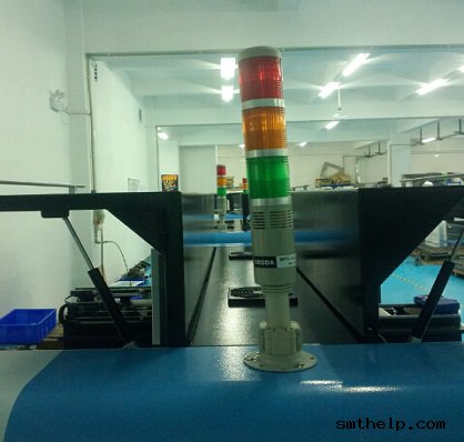
Skoda alarm, let you know the pick and place machines working condition clearly:

The highest capacity LED light board pick and place assemble machine


AI spare parts、Universal Parts,UIC,TDK.VCD Sequencer.SMT,THT,PCB,PCBA,AI,wave soldering,reflow oven,nozzle,feeder,wave soldering,PCB Assembly, LED, LED lamp, LED display

One Video show you how to auto insertion Odd form Component for Electronic manufacturing

PCBA Auto Insertion  – Axial, DIP, Radial, Pin, Odd-Form

We design and manufacture Odd Form component auto insertion machine,SMT equipment, and providing spare parts service. Worldwide Installation and on site support and training.

The primary sources for (new) automated through hole component insertion or through hole component assembly equipment today, are: Contact Systems, Fuji, Panasonic, TDK and Universal Instruments. All (5) OEMs have contributed to the advancements in equipment and technology that we use today to assemble printed circuit boards, and all provide spare parts and varying levels of technical support.


Contact System’s semi-automatic component insertion systems are capable of processing a wide range of components, including: axial, radial, dip, sip and even many odd-form devices. Although Contact’s machine are most commonly used to augment fully automatic assembly processes, it is not unusual to see the Contact Systems CS 400D and CS 400E component locators being used as the primary means of assembling printed circuit boards at many low to moderate volume manufacturing facilities. All CS 400 systems are ergonomically designed to minimize operator fatigue and maximize productivity by combining a convenient operator to machine interface with several types of parts delivery systems, including their: CS 210 Rotary Bin, CS 400LPD – Large Parts Dispenser, CS 241 Lighted DIP Dispenser and the CS 740 JIT Component Delivery Systems which are available in single ( CS 740BS ) and double picker ( CS 740BD ) configurations.

Contact System’s Ultra Clinch offers the unique feature of allowing the user to program lead lengths and clinch angles for each and every component being assembled.

Component insertion rates of 600 pph to 1,500 pph are typical.

Universal Instruments Corporation manufactures a complete line of through hole insertion equipment. Also known as Insertion Mounted Component ( IMC ) and pin in hole assembly equipment, UIC offers automatic component insertion platforms for: Axial, DIP, Pin, Radial, SIP, LED, Transistor and Odd-form devices.

Universal’s IMC line of axial component processing equipment includes:

Axial component sequencers that are available in the following models: 2596R, 2596A, 2596B, 2596C and 2596D. The expandable axial sequencers can be configured with: 20 to 220 stations using (20) station add-on modules, expanded range verifiers (ERV), refire, pass-thru or single board transfer – SBT . The typical yield rate of a Universal sequencer ranges from 12,000 pph to 25,000 pph.
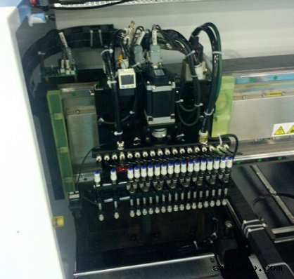
To compliment the 2596 sequencer, Universal offers the following axial component insertion systems: 6285, 6287, 6287A, 6287B, Generation 8, VCD single head 8 and model 6295 dual head VCD. Other VCD based inserters include the Jumper wire single head 8 and Jumper wire dual head 8. The cycle rates of these machines range from 8,500 pph to 40,000 pph depending on their configuration and vintage. Aside from cycle rates their operating parameters are similar.

As an alternative to stand alone equipment, Universal also offers a combined sequencer/inserter for axial leaded devices. Referred to as: 6241, 6241A, 6241B, 6241C, 6241D, 6248/48F, VCD Sequencer 8 Inserter, these axial lead sequencer / inserters can be configured with the same features as stand alone equipment.

Universal’s DIP Inserter product line include: Uni-module, Multi-module and SIP platforms. Available options include: 4 Pin DIP LED Tooling, DIP/Socket tooling, Autostick, and Single Board Transfer. The single head Uni-mod or model 6796 will typically yield 2,500 pph to 3,200 pph. The dual head Multi-mod or model 6772 typically yields 3,400 pph to 4,200 pph.

Universal’s Radial Sequencer/Inserter product line inserts radially taped and reeled components with body diameters up to 13mm and lead spans of 2.5/5mm at speeds ranging from 6,500 pph to 11,000 pph. Often referred to as Rad 1, Rad 2, Rad 3, Rad 5 and Rad 8 machines, these platforms can be configured with: 20 to 80 stations, single board transfer – SBT and expanded range verifiers – ERV. Model numbers associated with the Radial products include: 6346, 6348, 6358, 6360 and 6380.

Fuji, Panasonic Factory Automation and TDK offer competitive products, including: Fuji’s Flexible Board Assembler – FBA, Panasonic’s RH & AV and TDK’s RH.


AI spare parts、Universal Parts,UIC,TDK.VCD Sequencer.SMT,THT,PCB,PCBA,AI,wave soldering,reflow oven,nozzle,feeder,wave soldering,PCB Assembly, LED, LED lamp, LED display AI spare parts、Universal Parts,UIC,TDK.VCD Sequencer.SMT,THT,PCB,PCBA,AI,wave soldering,reflow oven,nozzle,feeder,wave soldering,PCB Assembly, LED, LED lamp, LED display AI spare parts、Universal Parts,UIC,TDK.VCD Sequencer.SMT,THT,PCB,PCBA,AI,wave soldering,reflow oven,nozzle,feeder,wave soldering,PCB Assembly, LED, LED lamp, LED display AI spare parts、Universal Parts,UIC,TDK.VCD Sequencer.SMT,THT,PCB,PCBA,AI,wave soldering,reflow oven,nozzle,feeder,wave soldering,PCB Assembly, LED, LED lamp, LED display