How to prevent static electricity in the process of SMT placement machine?
Southern Machinery Anti Static Tools & Supplies
In the SMT production line, we will encounter the problem of static electricity, from the friction between the clothes and the dry air to the dry air, which is the end of the duckweed. If the condition is suitable, it is a few volts and the peak is hundreds of kilovolts, so anti static is the need to do in our work, today, the south. Give some measures to introduce mechanical anti electrostatic patch SMT.
Static electricity has three: static clothing, antistatic shoes (conductive shoes), electrostatic hand rings, antistatic shoes and electrostatic hand rings to guide the human body to avoid accumulation in the human body.
Ordinary clothes will have great electrostatic voltage in the walk (>1000V). And antistatic clothing does not happen when it moves. This is the main role of antistatic clothing, long strip antistatic clothing can not shield the inside of the clothing produced static (after wearing still >1000V), grid – like antistatic clothing can be shielded (<200V), the static electricity generated through the floor and the grounding line of various parts of the plant to the outside of the general grounding wire.
1, strengthen the consciousness of the workers on the anti static operation
2, reduce the poor production caused by static electricity
3, prevent static electricity from causing damage to the product
二,Scope of application: all SMT production lines
三,The reasons
The generation of static electricity is not perceived, but the static electricity produces the voltage of tens of thousands of volts. When the static electricity comes into the tip (the static release point, such as the human finger), it releases all the energy in a moment, causing the contact material to be struck by electric shock, causing the capacitance, IC, line road and so on to be destroyed and burned, so that the product is strict. In the case of heavy damage, static electricity measures should be taken. .
四,The contents of the operation
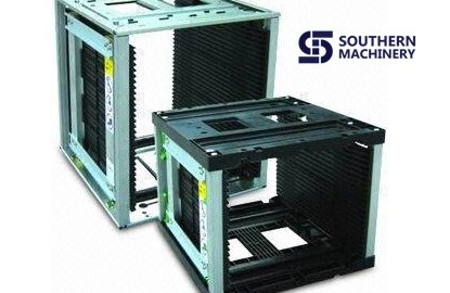
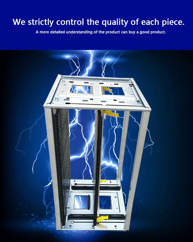
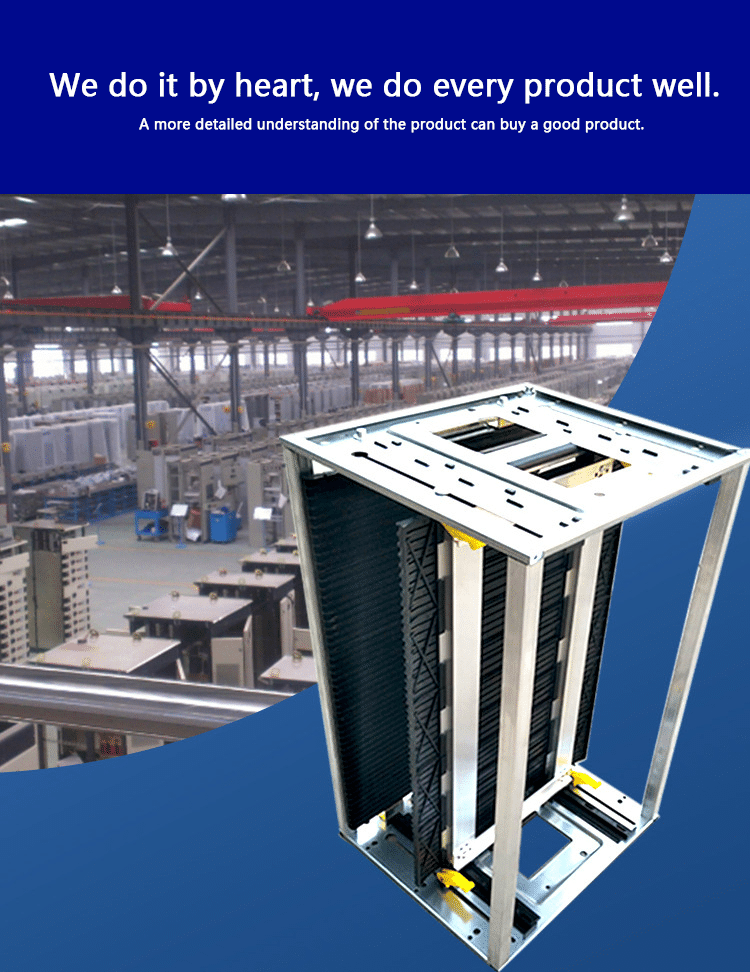
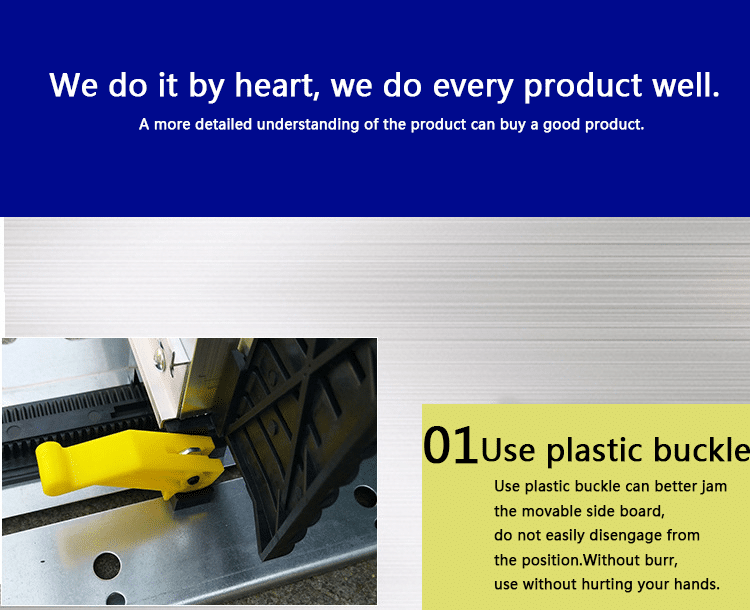
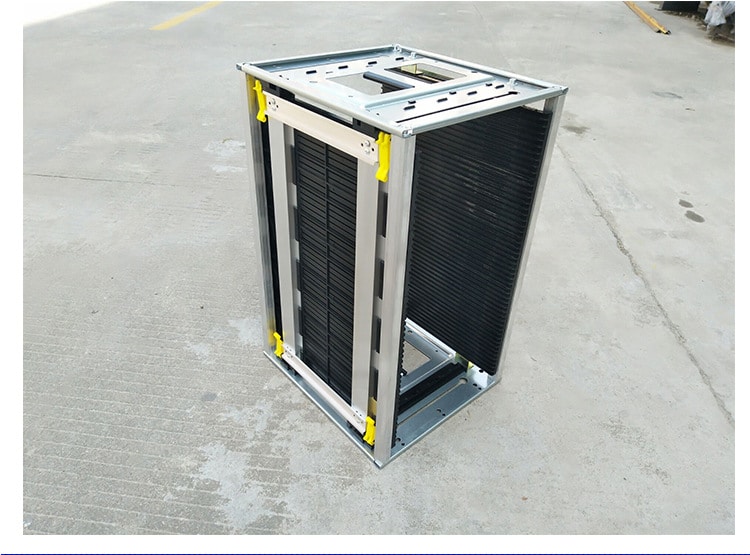
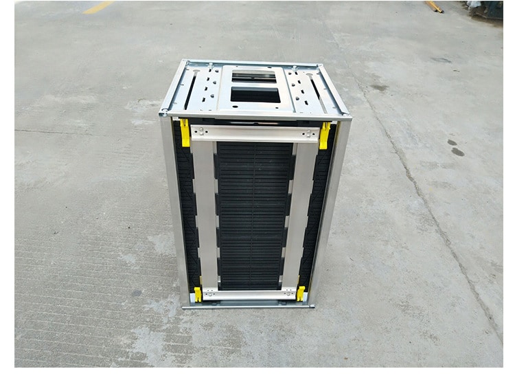
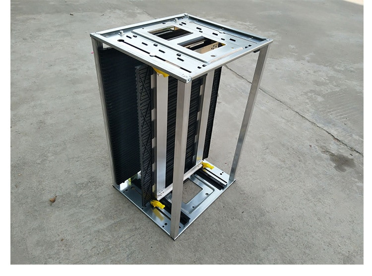
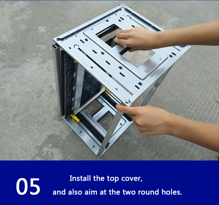
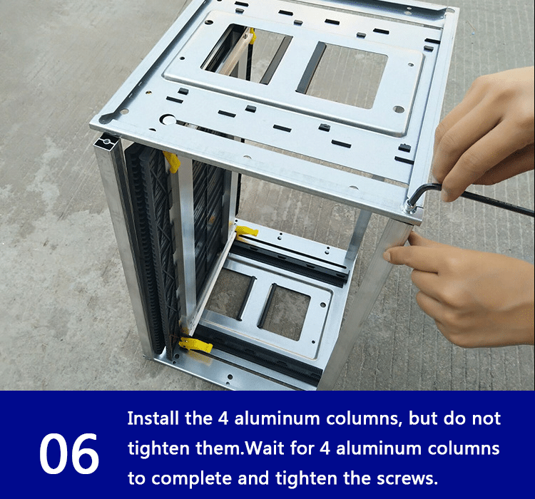
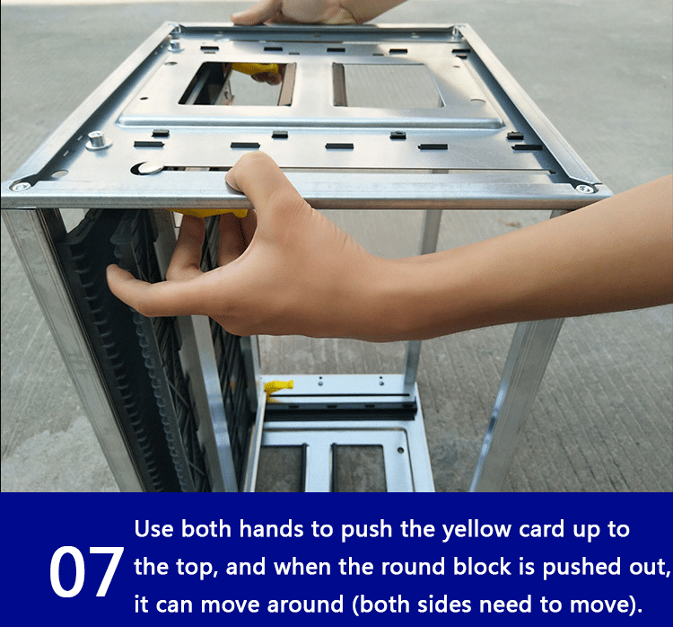
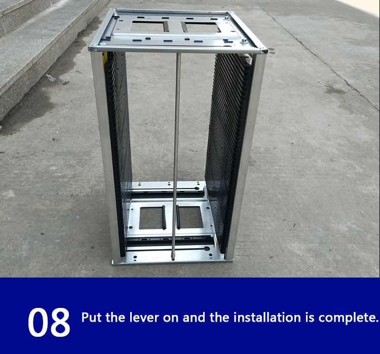
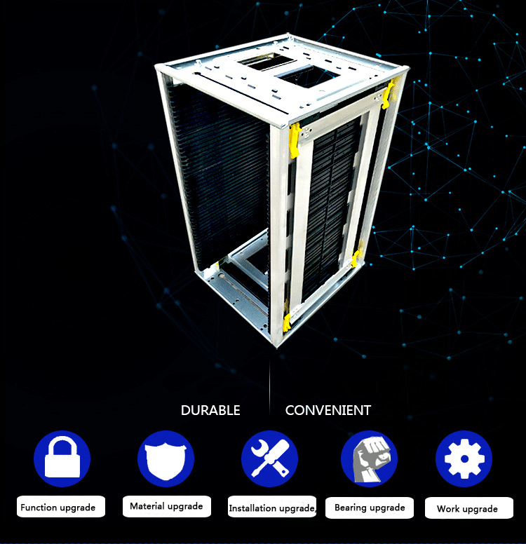
Anti Static Tools & Supplies SMT magazine rack&turnover rack
(一)Prevention and treatment of human static electricity
1, the workers should wear electrostatic clothing, work shoes;
2, the operator should take electrostatic gloves when working.
3, the operator should take an electrostatic ring in the operation.
(二)Prevention and control of static electricity
Make use of electrostatic materials to produce production tools.
2, the storage place to prevent static electricity;
(三)Prevention and control of static electricity of a worktable / mobile vehicle
1, the anti static film should be pasted on the work table.
2, the operation platform / mobile vehicle must have antistatic grounding chain.Prevention of equipment static electricity: good grounding wire
(四)Prevention and control of material static electricity
When the material is taken, the operator should use the antistatic method: with electrostatic gloves and electrostatic rings.
2, the material storage should be anti static measures: material cabinet to paste electrostatic film, grounding chain.
3, there should be anti-static measures in temporary storage area: installing grounding chain.
(五)Prevention and control of static electricity related to production: anti static measures should be taken when using items related to production: static wires and antistatic films.
五, Note:
The online operators should strictly abide by this rule
The online operators are supervised by the team leader, and the engineers are supervised by the engineers.
Troubleshooting E-Stop and Interlock Circuits on the Machine
Instructor Guide
IM8ECTT-IG Rev B
Troubleshooting E-Stop and Interlock Circuits
On the Machine
Estimated Time
3 hours
Prerequisite setups and materials
These setups and materials are required before this module is presented:
IM8ECTT Study Guide (1 per trainee)
Machine in operating condition
Introduction
The E-Stop and interlock circuits on Universal‘s products are designed to ensure that axis operation can occur only when these safety circuits are satisfied. The E-Stop and Interlock safety circuit is hard-wired and will perform its function independent of machine software.
In this lesson, you will look at the E-Stop and Interlock safety circuit in detail. Once you understand how it works you will get some practical experiences in troubleshooting this circuit.
Lesson Objectives
Trace E-Stop/Interlock circuit at machine and check the Interlock system with the job aid provided.
Given a machine with a fault in the E-Stop/Interlock circuit, locate and repair the fault using information in the study guide and the MSD.
Instructional Strategy for the module
Discuss European Safety Standards
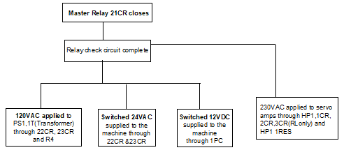
Discuss sequence of events of E-Stop and Safety interlock and how they relate to power distribution
Trace the troubleshooting steps:
Before E-Stop
After E-Stop
Interlock Made
After Start
European Safety Standards
European Safety Standard
Universal‘s E-Stop and Interlock circuit is in compliance with European Safety Standards, which include the following requirements:
Use of redundancy (i.e., two mechanical relays to disable dangerous voltages)
Use of contacts which move together and are positive guided (no contact can be in the de-energized state if one contact is stuck in the energized state)
All relays must have a normally closed contact used to test the relays.
the E-Stop and Interlock Circuits
Introduction
This activity is intended to give you some practical experiences in troubleshooting the E-Stop and Interlock Circuits on a machine. In this activity your instructor will put one or more bugs in the machine E-Stop and Interlock circuits. Your job is to find and fix the bugs so that the machine is returned to normal operation.
CAUTION!
High voltage is present on the machine when power is turned on. Take great care when troubleshooting the electrical assemblies in the machine!
Whenever possible, never reach into an electrical assembly when the machine power is on.
Use extreme caution when connecting or disconnecting a multimeter. When the situation warrants, use test probe clips to connect the multimeter to test points with power off at the assembly*, then apply power to read the meter; and turn assembly power off before disconnecting the meter.
*An E-Stop or circuit breaker can often be used to remove assembly power.
Directions
Working in a small group (never alone), locate and repair the bugs put into the machine by the instructor. The machine must be returned to normal operating condition when you have completed your work.
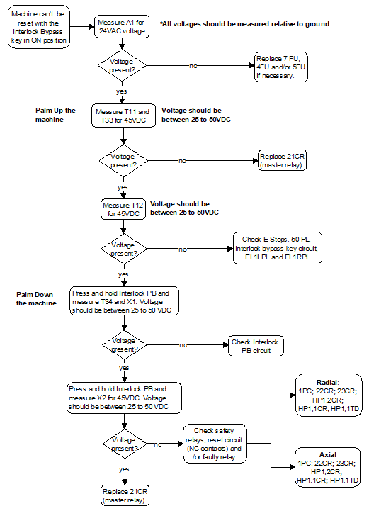
It is strongly recommended that you follow a sequence when troubleshooting the E-Stop and Interlock system. The Troubleshooting Flow Chart on the following page should help you determine what part of the subsystem is not working.
When looking for machine-specific information, always refer to the electrical diagrams that come with the machine on which you are working.
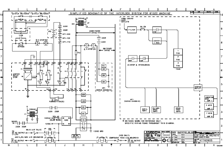
Simplified Schematic of the Interlock System for Single Head Axial Machines
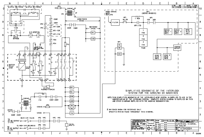
Simplified Schematic of the Interlock System for 6241FSimplified Schematic of the Interlock System for Dual Head Axial Machines
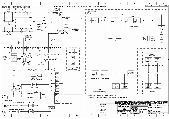
Simplified Schematic of the Interlock System for 6380A
Trace signals in the electrical schematics to answer the following questions.
24VAC is delivered to 4TB at pins 31 through.35 and 91 through 95. Find where pin 31 is connected to
5FU-Side (SHT2)
This question refers to the drawings for PS1, trace it from the secondary side of 2T (24V SEC) and is tied in with 5FU (sheet 2)
What happens when the contacts between pins 1 and 2 close in both 22CR and 23CR?
56VDC is supplied to 4TB
Connects 56 VDC from secondary of 1T to 4TB distribution point to X-Y table motors.
When you suspect that the 24VAC or a DC voltage is missing from the machine, which electrical schematics should you use to troubleshoot the machine?
the “ELECT DIAG, Power chassis” schematic
Ask students: You lost 24VAC, where it’s generated from? (the inserter’s power chassis, PS1.) Where do you find that drawing? ELEC DIAG, Power Chassis.
E-Stop Circuit Active
Direction
Using the simplified schematic, individually trace and describe the E-stop and interlock circuit of an IM8 machine
Work in a small group, locate and repair the faulty E-Stop and Interlock circuits. Use your notes, flowchart and MSD.
Instructor notes: the following table lists suggested bugs to simulate an E-stop and Interlock circuit problem.
Problem
Simulation Method
24VAC to PS is lost
Remove 7FU, 4FU, or 5FU
21CR can’t be energized
Disconnect X1 and X2
Relay problem
Disconnect at contact 21 or 22 of 22CR and 23CR (Interlock system will not enable)
Chip bonder counter can precisely count the SMD quantity, by adopting optical and electric sensor theory, using the corresponding relation between guide hole on the carrier and part, and by the special die and massive integrated circuit, chip bonder counter achieve zero error, and achieve convenient, quick counting, it is an effective auxiliary equipment for managing SMT material.
2、Product features
With full automatic way figure part quantity, it is convenient to count and delivery material. Easily operate it, original design defending strip dropping off decrease strip hurt to a smallest extent. It can count in forward direction or in backward direction, and it can be preset value, precisely figure out quantity with zero error. You also can install scanner gun and barcode printer, which is more convenient for managing operation..
3、product specification
Power: AC220V,50/60HZ,25W
Counter range: -99999–99999PCS
Profile size: L470W300H180mm
Weight: 10KG
4、Product Utility
Suit for SMD strip type of part
Strip wheel diameter: suit for any size
Strip pitch: 1,2,4,8,10,12,16,24,32,44,56mm ( Note: if pitch is smaller or wider, make it according to customer’s request)
Strip width: 4,6,8,12,16,24,32,44,56mm (Note: if width is smaller or wider, make it according to customer’s request)
5、Product Structure
this product have two types.
S-CC200 Standard chip bonder counter
2) S-CC202 inspecting missing type chip bonder counter
1、material reflector
2、Tray
3、Gear/motive pressing plate
4、monkey wrench
5、rocket head
6、free movable shoulder
7、location knob
8、display
9、key
10、power key
11、handle
12、glass fiber amplifier
13、glass fiber head to head emitter
二、Chip bonder counter attention
1,After unpacking, please count and make sure all accessories ready.
2,Before using chip bonder counter, please carefully read operating instructions and safe keeping.
3,Please check whether voltage specification conform to the electric supply.
4,Please check grounding properly, and guarantee safety of human body and part.
三、Chip bonder counter function key and operating instructions
1、Function key introduction
1)”PRINT”
Operation way: enter the key, you can print the counting part and quantity on the barcode by the barcode printer.
2)”SET”
Operation way: if the display shows 00000 in the left bottom, you can directly press the number key to input the counting part quantity; press the SET key one more time, the machine switches to manual mode, and the display shows ***** in the left bottom. Switch to manual mode or automatic mode using this key. (note: under automatic mode, you can preset a value before counting material, when machine turn to the presetting value, it will automatically stop, under manual mode, only if you press ” stop/zero clearing” key or it finishes all material, the machine will stop.)
3)”PITCH”
Operation way: after pressing this key, the pitch value in the display will flicker, then you can input the pitch value and press “ENTER” key, if no press after 5 second, automatically memorize, the machine will resume to standby status after one ticking sound.
4)”RIGHT” “FOREWARD/RIGHT”
Operation way: Pressing this key, start clockwise counting part, the numerical value is positive number, “BACKWARD/LEFT” on the contrary.
5) “STOP/ZERO CLEARING”
Operation way:
(1)Under counting or feeding back status, press this key, it will stop counting or feeding back.
(2)If under standby status, press this key over 2 second, the counting value will be cleared up.
(3)If under printing interface, press this key, return to main interface.
6)”SELECT”, this key is switching key for setting parameters in printing interface.
8)”Time/missing stop” key is switching key for motor rotating speed, press this key, LCD display will show motor speed will be switched among H(high speed), M(middle speed), L(low speed).
2、 Operation Flow
1)Connect the power cable to the master machine, and plug the AC220V power.
2)Turn on the POWER key on the panel of machine, at this time, LCD panel become light
3)Press PITCH key, set the pitch between counting parts, then Press “ENTER”, and put the part on the left tray.
4)Manually pull out the strip and put it between material guard plate and counting gear, make the first part and blank middle hole aligning the middle line of material guard plate.
5)Press “STOP/ZERO CLEARING” key for 2 seconds, make the value zero clearing. Note: when pulling the strip, counting gear will turn and count, pressing this key, make the value zero clearing.
6)Press “SET” key to switch to manual mode or automatic mode, when you select automatic mode, you should input a value which you are going to count, or the “FORWARD” motor won’t start.
7)Pull strip coiling to the blank tray (right tray) by your hand, press “FOREWARD/RIGHT” to begin counting.
8)When finishing preset value, motor stop. Impacted by the inertia theory, counting number may be more one or less one than the set number,
9)When finishing counting, press “BACKWARD/LEFT”, strip will coil back to the left tray, after finishing, rotation will stop.
2)Start bar code master machine power switch: power pilot light and ready pilot light are on, at moment, press FEED key of bar code master machine (automatic aligning key), make the paper automatically align. ( P.S: if power light is flickering, it denotes the machine is off line, please restart power or repress FEED key)
3、Print
Press “PRINT” key in the master interface, master interface will display printing interface, the first row in the interface show: company name (you can set it by yourself); the second row show: time, the last row show printing operation.
When entering printing interface, there is a flickering cursor in the third row, you can edit and modify the content in the cursor position.
In the printing interface, pressing LEFT/BACKWARD, you can make the cursor move left, pressing RIGHT/FOREWARD, you can make the cursor move right.
In the cursor position, you can directly input the number or letter, if you continually press any key among 0~9 key in a short time, you can switch between number and letter on the key. Among of them, pressing 1 key, you can switch to special symbol, Capital letter, small letter, and etc.
After editing each row, cursor will stay in the row you are editing, press “ENTER” key, it will display OK in the left of this row, which means the content is saved.
Note: Saving the content in the editing row, only when cursor is in this row, and then press ENTER, the content can be saved. For example, if you want to save the content in the first row and second row, when cursor is in the first row, you press ENTER key, at the moment, only the content in the first row is saved, the content in the second row can’t be saved.
In the printing interface, press SELECT key into printing parameter setting interface, XYWH: XXX XXX XXX XXX showed in this interface separately denote X axis, Y axis, width, height which you can set to the printed barcode paper.
Press STOP/ZERO CLEARING back to master interface
Press PRINT key one more time, you can print the content in the printing interface.
Tag: when scanner scans barcode, it will display in the printing interface, press PRINT key to print.
五、Easy trouble shoot
Failure
debug method
After turning on power, LCD no display, buzzer no sound
Please check if power cable drop off or fuse loosen
。After turning on power, LCD no display, buzzer sound
LCD display cable loosens or breakdown, please check or contact dealer to change.
LCD normally displays, but FOREWARD/BACKWARD can’t be started.
The counting quantity is more than or equal to the set value, or selecting automatic mode before counting but not set quantity, please refer to operating instructions.
2.Motor signal cable or power cable bad contact.
六、After-sale service a: (overall unit maintenance period for one year, master controller board maintenance period for three years, and tended for all life.) the following state happened is not in the free maintenance condition.
Machine is damaged under carried by your person by himself
In unstable voltage region, due to not using voltage stabilizer, cause component damaged.
Due to not using correct voltage, cause component damaged
Due to altering machine without the written approval of our company, cause the machine damaged..
Not selled by our company, but selled by dealer or other factory.
1. Obtain the proper shop packet and check order for build information. Pull all parts if any parts are missing, fill out a shortage sheet and give a copy to the appropriate material coordinator.
2. Pull the latest Electrical and Mechanical prints.
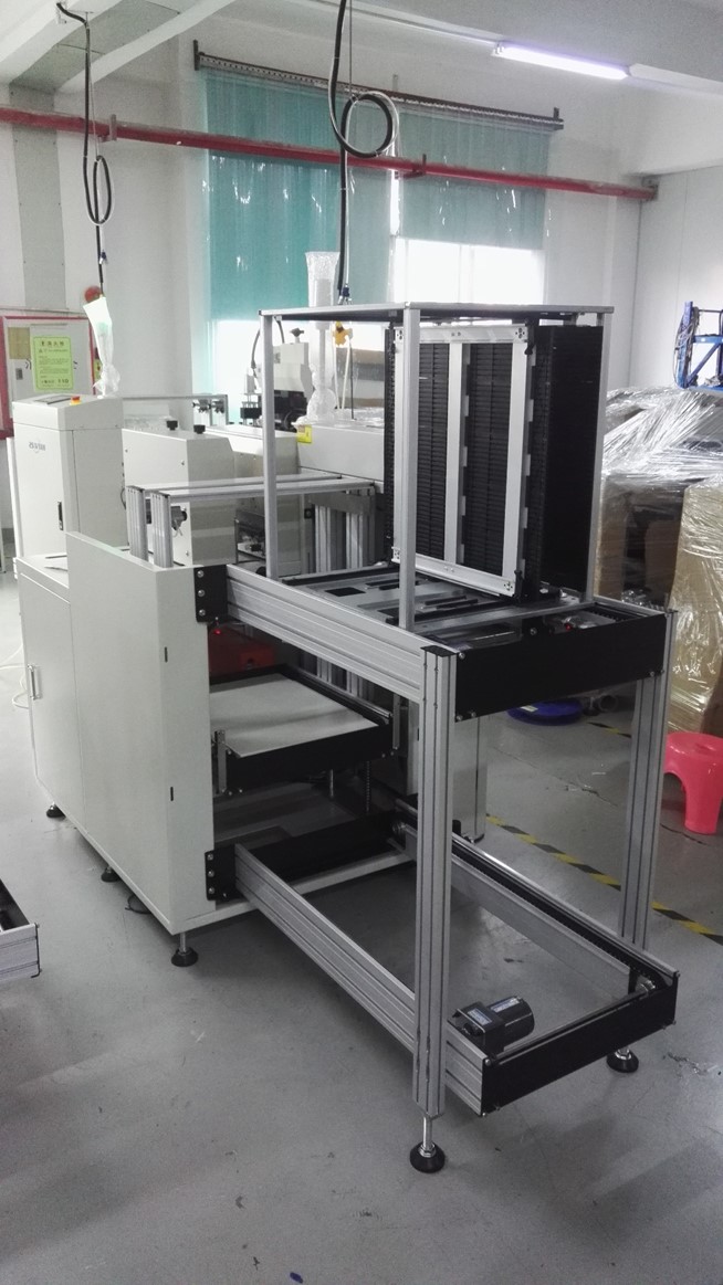
3. The following procedure is for a 29″ Destacker. Attach leg and control box to main beam. Leg should be flush to left side of main beam. Control box should be 3″ from right side of main beam. Attach width units to main beam, 4-3/8″ from either end square to main beam and Parallel to each other.
4. The following procedure is for the 44″ and 58″ Destackers Attach leg and control box to main beam. Leg 7-5/8″ from left end control box 7-5/8″ from right end. Attach width units to main beam 8.975″ from either end. Square to main beam and parallel to each other.
5. Attach rear rail to width supports parallel to main beam 3/8″ overhand from either end of main beam.
6. Level conveyor from side to side and front to back, off rear rail
7. Attach front rail to width supports. Match level to rear rail, especially front to back. Make parallel to rear rail. Make ends even with rear rail.
8. Install motors, pulleys, UHMW and belts on rails.
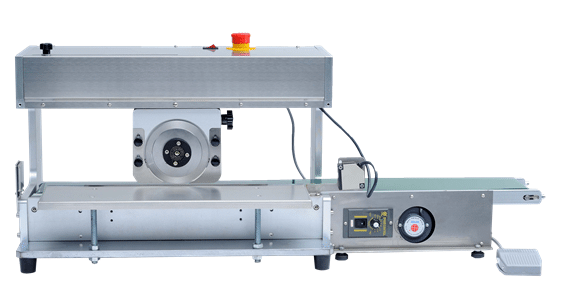
1. To connect multiple pieces of the board after the solder, broken often damage the circuit or break the electronic components, the machine to move the knife to split, which can completely reduce the stress, to prevent solder cracking and parts cracking, improve production efficiency and quality . 2. Using the knife on the knife under the flat knife, the plate as the next flat knife, switch a step on the round knife moving to the set point of the move, about to cut off the PCB board, cut off without silk, incision formation, no flash.
Features:
1. Completely independent development, the use of microcomputer control, precision fixed point, strong stability. A knife cut off within 0-360MM long single board;
2. Cutting board cutting speed can be adjusted high, low two, speed 500mm / S and 300mm / S, fast speed, you can improve product quality, no flash, no glitches;
3 knife travel: 0-500mm (tool length can be customized). Knife round height adjustment: 0-2mm for a variety of PCB thickness to solve the problem of PCB board V-CUT slot depth. Console adjustable height: 0-50mm;
4. Traveling stroke can be set with the length of the board forward stop fixed point, stop fixed point set manually;
5. Rear baffle depth range: unlimited. Maximum plate cutting width: unlimited, maximum plate cutting length: 360mm, the maximum thickness of the plate: 0.2-5mm, the maximum thickness between the V tank: 0.25-2.0mm;
6, the next knife for the import of high-speed steel, durable extremely, when the knife adverse, you can then grinding;
7. Can be matched with additional conveyor belt, easy to cut PCB board automatically sent;
8. lifting platform platform movements, platform elevation, can affect the quality of the product, not easy to cut the product can reduce stress;
9. Limit device, you can apply different sizes of products, thereby enhancing work efficiency;
Technical data:
Power: Single-phase AC230 / 110V 50-60HZ, 40W
Machine size: L823 * 405 * 425mm
Net weight: 350Kg
Tool Material: SHD61 imported high-speed steel,
On the round knife: diameter 125mm, under the straight knife length: 500mm
SC-509 V-cut PCB Separator Machine with Moveable Cutting Blade
Features:
To connect multiple pieces of the board after the solder, broken often damage the circuit or break the electronic components, the machine to move the knife to split, which can completely reduce the stress, to prevent solder cracking and parts cracking, improve production efficiency and quality .
Using the knife on the knife under the flat knife, the plate as the next flat knife, switch a step on the circular knife move to the set point of the move, the PCB will be cut off the cut, cut off without silk, incision formation, no flash
Features:
Completely independent development, the use of microcomputer control, precision fixed point, strong stability. Cut off a single board within 0-360MM long
Cutting board cutting speed can be adjusted high, low two, the speed of 500mm / S and 300mm / S
Knife wheel path: 0-360mm. Knife round height adjustment: 0-2mm for a variety of PCB thickness to solve the problem of PCB board V-CUT slot depth. Console adjustable height: 0-50mm.
The path of travel can be set with the length of the board forward stop fixed point, stop fixed point set manually
Rear baffle depth range: unlimited. Maximum board cut-off width: Unlimited, Maximum board cut-off length: 360mm, Board maximum thickness: 0.2-5mm, Maximum slot thickness between slots: 0.25-2.0mm
Upper and lower knives for the import of high-speed steel, extremely durable, when the knife negative, can be re-ground
Can also be an additional set of conveyor belt, easy to cut the PCB automatically sent
lifting platform platform movements, the platform elevation, can affect the quality of the product, not easy to cut the product can also reduce stress
Limit device, you can apply different sizes of products, thereby enhancing work efficiency
Specifications:
Power: Single-phase AC230 / 110V 50-60HZ, 40W
Machine size: L1000 * W395 * H425mm
Packing size: L1100 * W420 * H450mm,
Conveyor belt size: L1030mm * W220mm * H130mm
Net weight: 47Kg, Package weight:
Tool Material: SKD61 imports of high-speed steel, the round knife: diameter 125mm, the next straight knife length: 360mm
Basic maintenance:
1, the work is completed, turn off the power, remove debris.
2, always pay attention to the upper and lower cutter protection.
3, a long time not working, please remove the upper and lower cutter, and coated with oil to be protected, please wipe before use.
4, pay attention to check the fastening of the screws.
1, using the next vacuum mode, in line with the theory of free fall, good dust collection effect.
2, special jig fixed more solid, to avoid the poor positioning caused by the cutting accuracy error.
3, the system automatically fixes according to the product installation location, to ensure high-precision product cutting requirements.
4, the static eliminator is installed in addition to electricity, dust blower continued to work to eliminate static electricity generated when cutting high-speed spindle to avoid damage caused by static electricity parts to avoid accumulation of dust due to static electricity.
5, the use of safety doors, reduce noise and dust, improve safety.
Vacuum cleaner with vacuum collection box (according to production capacity or cutting dust collection time scheduled maintenance)
。
PCB Separator also called PWB Depaneling machine. Rotate router bit to cut high-density component PCB panel to single products v-groove or perforated line. Utilize all of our accumulated technology to help minimize dust attach on PCB. Router machine has following features.
The number of milling cutters (0-5 section)Break Detection断刀检测无(none)Cutter Life Control刀具寿命控制程序控制(controlled by Program)Table NumberTable数量1个Spindle Speed主轴转速60000rpmSpindle Cooling System主轴冷却系统气冷方式Air cooling modeCleaner Mode集尘方式下集尘(collect dust downside)Working Power工作电源220V ,50HZAir press空压供给0.4MpaSafety Device安全装置采用安全防护门加门锁感应器Safety door and door lock sensorMode机型模式离线机型,手工装载卸载PCBA(offline, load and unload PCBA by hand)Auto failure test and repair mode故障自动检知维修模式系统具有自我诊断功能,实时错误信息显示,能直观地查询设备各个IO端口状态,易于排除故障。
Self-diagnosis,display failure information in real time, query IO state visually, easy for troubleshootingComputer & Operation system电脑和操作系统工控机、Windows 7
IPC, Windows 7Program Backup程式备份USBSoftware access control软件权限管理密码保护,依权限进入对应操作界面,保护系统重要参数。(Password protection,the operator enter corresponding interface according to authority to protect important parameters.)Programming编程可视化界面,单个程序切割点容量无限制,切割路径动态模拟。(Visual interface, the cutting point capacity for a single program should be over 400, dynamic simulation of cutting schedule.)Auto correction of the mark pointMark点自动校准功能具备Mark点自动校准功能(Yes)Fixture 治具万用治具可供选择(universal fixture)Voice control噪音控制运行时,噪声小于60分贝(离设备一米距离测量)
≦78 dB(measured in 1M’s distance )Maintenance Period保修周期整机1年或以上,主轴2年或主轴3000小时保养服务。
1 years or more, spindle for 2 years or spindle maintenance service for 3000 hours.Technology Support技术支持及培训提供设备操作、编程,硬件保养,维修培训服务;程序永久免费升级。(Offer service of operation, programming, hardware caring and maintenance training; free upgrade of application. )
1, vacuum cleaner built-in vacuum mode, in line with the theory of free fall, dust collection effect is good.
2, the equipment adopts automatic loading and unloading products, can be directly on the wiring body or on the board machine.
3, using a special fixture with products (pcb), to avoid poor placement caused by cutting error.
4, the system automatically fixes the installation error, to ensure product precision cutting requirements.
5.It is equipped with static eliminator. When dividing, the dust remover will work continuously to eliminate the static electricity generated when the high-speed spindle cut. It can avoid the damage caused by the static electricity and avoid the accumulation of dust due to static electricity.
6, the use of safety doors, reduce noise and dust, improve safety.
7, there are follow-up vacuuming function, dust collector attached to the dust collection box (according to capacity cutting needs or dust collection time scheduled maintenance).
8, touch the display as a display, setting, control, can display more content, the operation directly through the touch screen operation, easy to operate.
9, can be directly docking the next equipment, sub-plate processing.
10, in the cutting process, if broken knife, equipment with automatic tool change function, without manual to change the knife.
11, Equipment using Mes system, the factory can control the machine everywhere, equipped with WIFI function can be controlled.
Specifications:
Function Items
功能项
Hardware Demand
Model
型号
ASC-3500S(加皮带)
Dimension
机台结构
(含皮带)L1750*W1100*H1850mm
(不含皮带)L1450W1100H1850mmPower
电源
220V/50HZMachine Wattage
机台功率
5.5KWWeight
重量
About1000KGCleaner Dimension
吸尘器尺寸
内置式(Inside)/L450W450H450mmCleaner Wattage
吸尘器功率
2.2KWTable Dimension
工作台尺寸
350mm*350mmCutting Speed
X、Y轴切割速度
0-100mm/sX,Y,Z axis Driving SpeedX、Y、Z轴驱动速度X、Y轴至少1000mm/s(min),Z轴至少750mm/s(min),伺服马达方式驱动(driven by servo motor)Repeatability Accuracy机台重复精度±0.02mmMechanical hand X, Z stroke机械手X、Z行程X:420mm、I:60mmManipulator X, Z running speed机械手X、Z运行速度200mm/sMechanical hand grasp mode机械手抓取方式真空吸附Precision of repeated positioning of manipulator机械手重复定位精度±0.04mmMechanical hand grab products (PCB) dimensions机械手抓取产品(PCB)尺寸350mm*350mmPCB feeding trackPCB上料轨道皮带输送;宽度60~360mm可调Split plate product分板产品下料皮带输送;宽度420mmWorking Area工作区域(可加工行程)X:300mm,Y:350mm,Z:0-50mmPCB Thickness切割PCB厚度范围0.5-2mm(or thicker),或范围更大 Router Bit Diameter铣刀直径0.8-2.0mmCutting Precision切割精度±0.01mmCutting Ability切割能力具有切割直线、圆弧、圆、L型和U型的能力
Smart to set the no. of knife section(0-3)Break Detection断刀检测有(have)Cutter Life Control刀具寿命控制程序控制(controlled by Program)Product testing产品检测有(have)Table NumberTable数量1个Table FunctionTable功能并行Table运行方式;设备能实现1个Table联动功能(1 tables run in parallel)Spindle Speed主轴转速60000rpmSpindle Cooling System主轴冷却系统风冷方式(air cooling)Cleaner Mode集尘方式下集尘(collect dust downside)Working Power工作电源220V ,50HZAir press空压供给0.5Mpa以上(above)Safety Device安全装置采用安全防护门或感应器(security door or sensor)Mode机型模式在线机型,全自动装载卸载PCBA(offline, load and unload PCBA by hand)Auto failure test and repair mode故障自动检知维修模式系统具有自我诊断功能,实时错误信息显示,能直观地查询设备各个IO端口状态,易于排除故障。
Self-diagnosis,display failure information in real time, query IO state visually, easy for troubleshootingComputer & Operation system电脑和操作系统工控机、Windows 7或以上版本。
PIC、Windows 7 or more advanced versionProgram Backup程式备份USBSoftware access control软件权限管理密码保护,依权限进入对应操作界面,保护系统重要参数。(Password protection,the operator enter corresponding interface according to authority to protect important parameters.)Programming编程可视化界面,单个程序切割点容量无限制,切割路径动态模拟。(Visual interface, the cutting point capacity for a single program should be over 400, dynamic simulation of cutting schedule.)Auto correction of the mark pointMark点自动校准功能具备Mark点自动校准功能(Yes)Fixture 治具ASC-3500S专用治具ASC-3500S special fixtureVoice control噪音控制运行时,噪声小于60分贝(离设备一米距离测量)
≦78 dB(measured in 1M’s distance )Maintenance Period保修周期整机1年或以上,主轴建议2年以上并在保内提供主轴3000小时保养服务。
Over 1 year for the whole machine, and over 2 years for the spindle, and the spindle enjoys 3000 hours’ maintenance during the periodTechnology Support技术支持及培训提供设备操作、编程,硬件保养,维修培训服务;程序永久免费升级。(Offer service of operation, programming, hardware caring and maintenance training; free upgrade of application. )
1, the use of multiple sets of upper and lower knife while cutting
2, the bottom of the device with adjustable foot castors, easy to move equipment, non-moving need to be stable and fixed; feet Cup adjustable height 50MM or more;
3, equipped with SMEMA interface communication with other devices can be linked, with reserved network interface, the follow-up factory aspects of networking;
4, the device uses power: AC230V gas source: 4-6KGF / cm2
5, the necessary safety devices;
6, the equipment needs to operate smoothly, the necessary test components;
7, according to the normal production capacity needs to reach 1500PCS / H or more
8, there are data monitoring statistics output: boot time monitoring, capacity monitoring, equipment failure information and automatic rejection system
9, using multiple groups simultaneously cut down on the knife
10, the distance between the knife can be accurately adjusted, sub-board thickness to be met: 0.6MM-3.5MM up and down the distance between the knife can be accurately adjusted, sub-board thickness to be met: 0.6MM-3.5MM
11, the knife and the knife gap can be adjusted according to the PCB board V-CUT spacing, precision control in the 0.1MM
12, the distance between two adjacent blades can be adjusted between 8MM-25MM, can quickly adjust the required width;
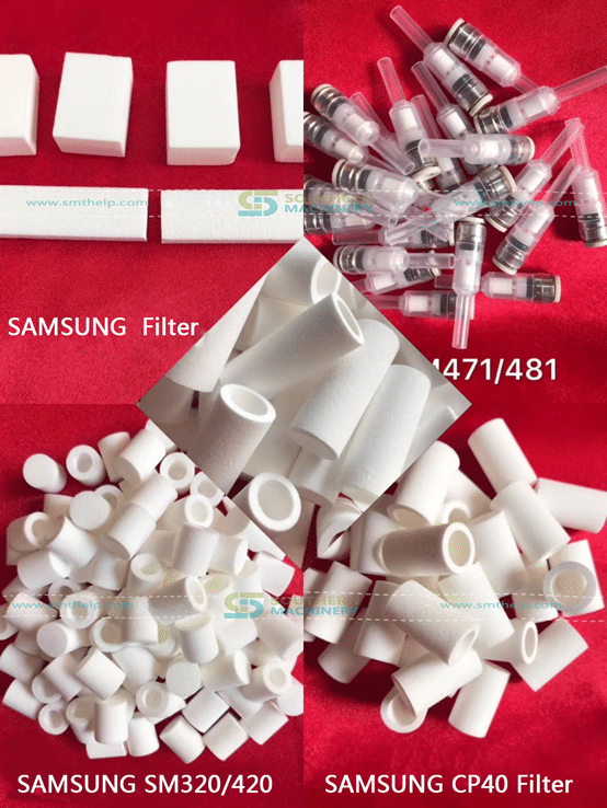
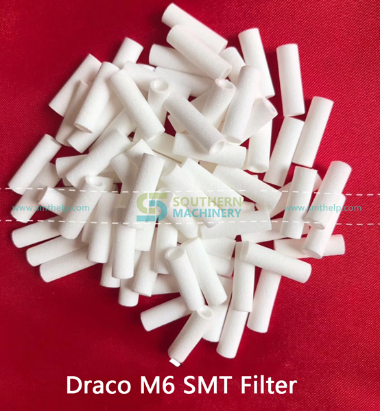
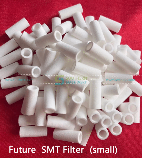
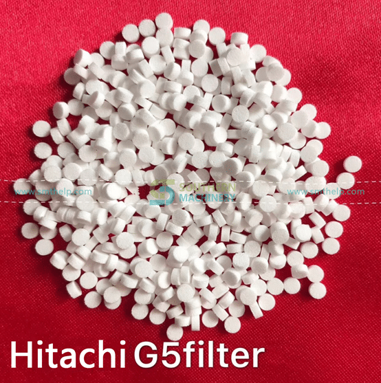
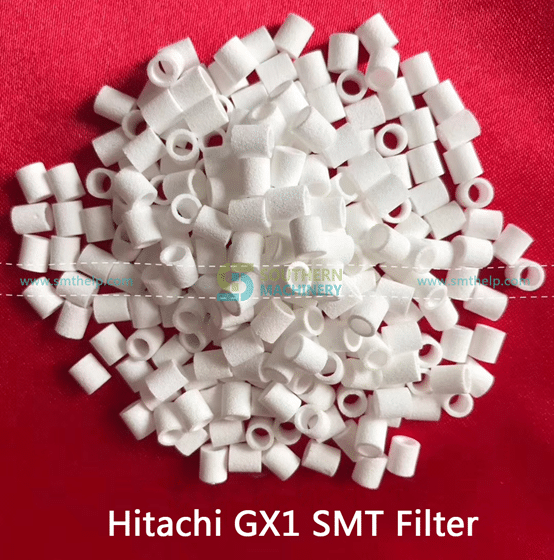
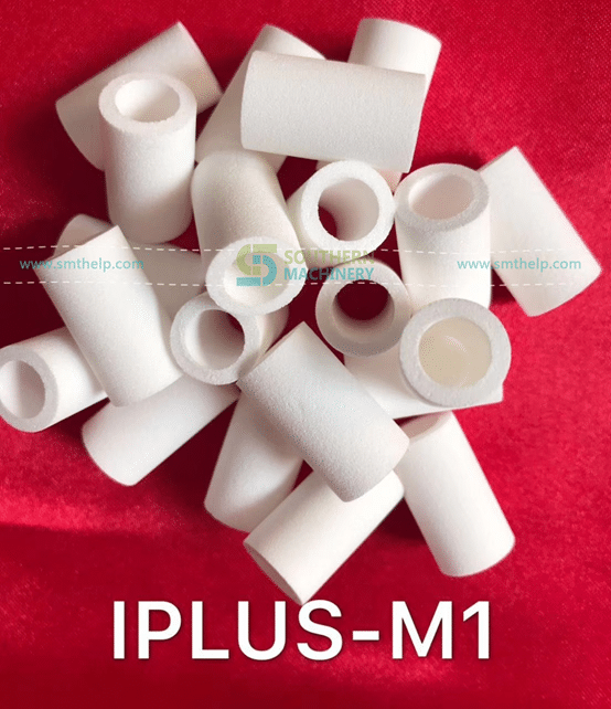
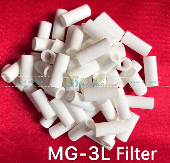
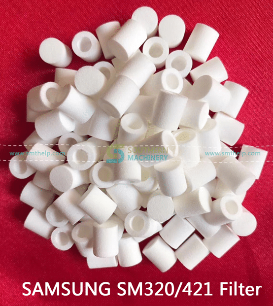
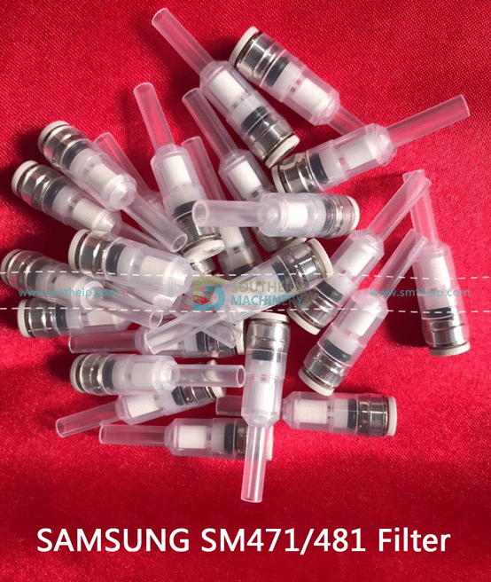
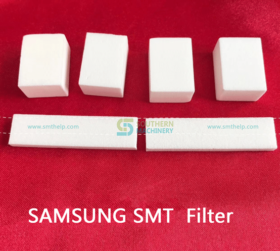
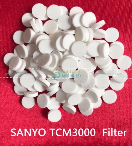
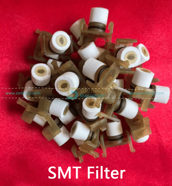
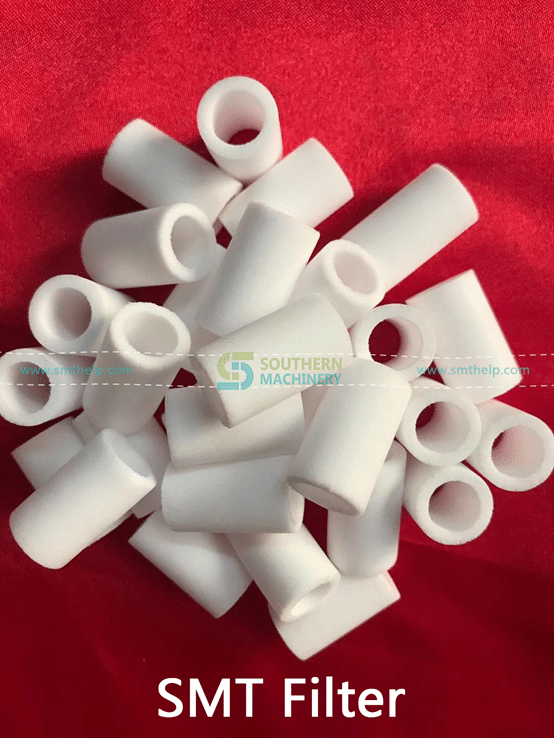
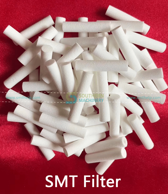
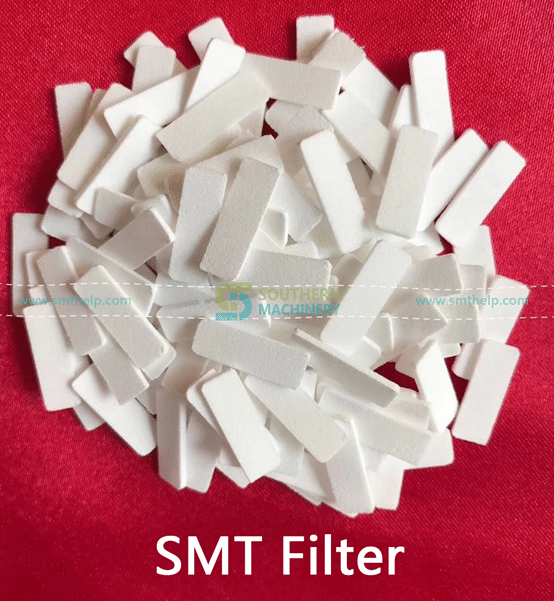
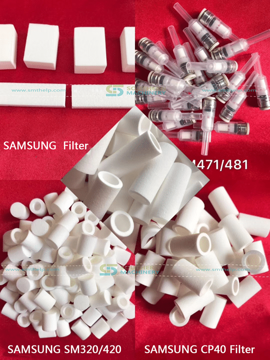
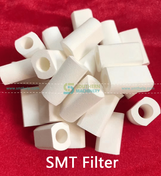
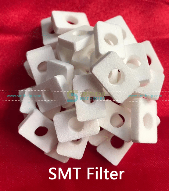
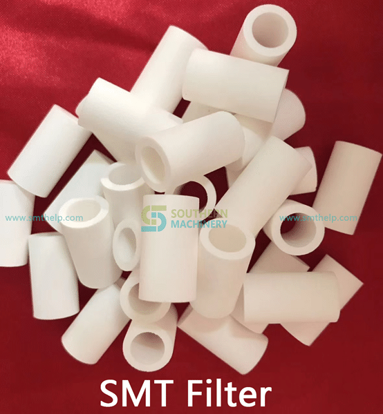
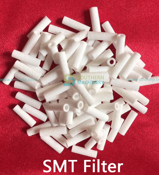
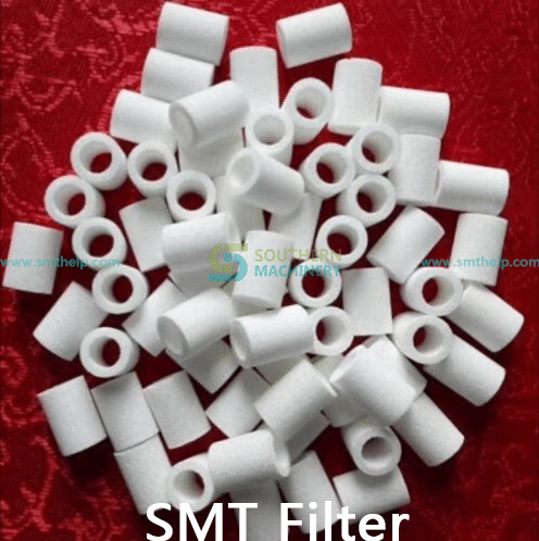
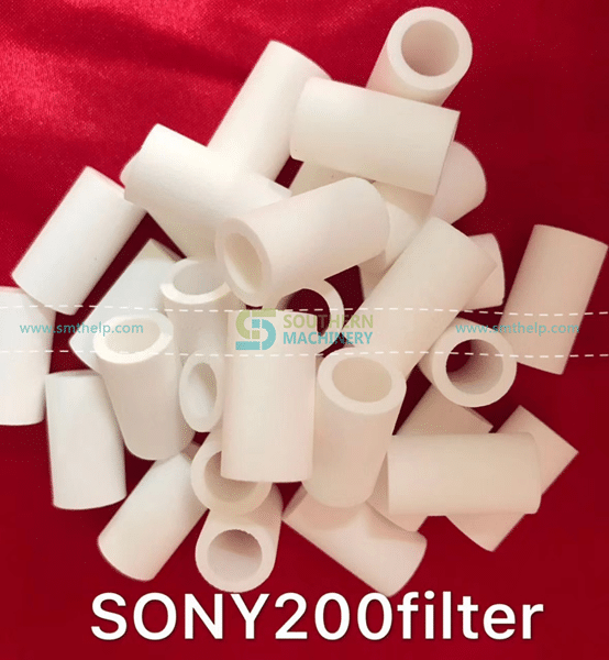
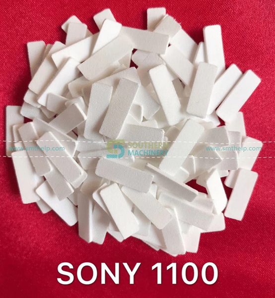
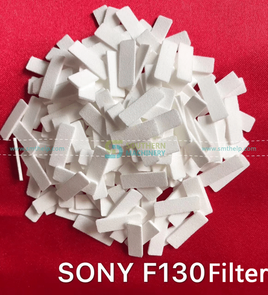
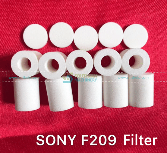
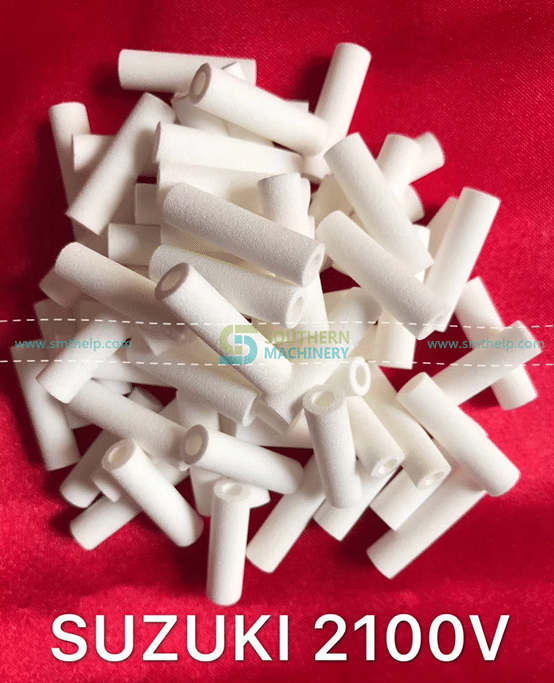
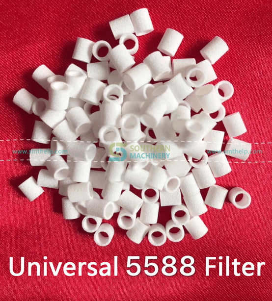
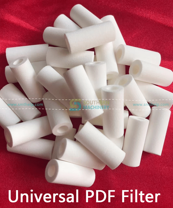
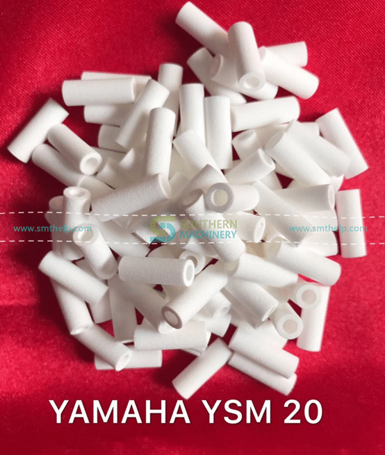
SMT filter cotton is usually replaced in three months, otherwise it will be blocked, affecting the use effect.
Filter has the following characteristics.
1.Is a high performance and high efficiency filter cotton non-woven processing using organic hot-melt synthetic fiber and;
2, increasing structure, using gradually encrypted multi-layer technology, that is, the fiber density in the direction of pure air will increase gradually, and the higher filtration efficiency can be blocked at different levels of density according to the size of dust, which will more effectively accommodate more dust.
3, efficient filter cotton sticky treatment, filter material after full dipping, because the adhesive penetrated the media completely, so that the dust particles can not pass through, so that the overall filtered air flow evenly diffused, forming laminar flow state, to achieve the best spraying effect.
Does anyone need SMT filter cotton? Factory price.