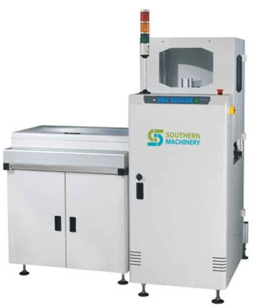
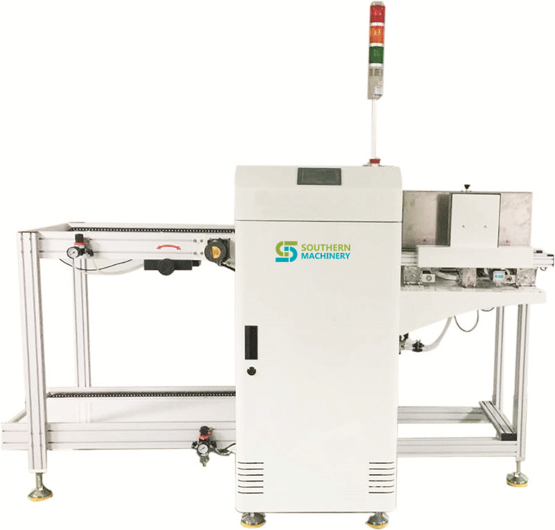
PCB Magazine Type Buffer Technical Parameters
• Description: This Device Used For Receiving NG Board Or Memory Board
• No.Of Magazine: Upper Conveyor: 1 Magazine; Lower Conveyor:2 Magazine
• Indexing Pitch: 10.20.30.40mm Or Specify
• Power Source: AC 110 Volts Or 220 Volts; Single Phase
• Power Consumption: Max 250VA
• Air Pressure & Air Consumption: 4-6bar, 15ltr/Min
• Transport Height: 900±20MM
• Transport Direction: From Left To Right Or Right To Left
It can be used to load PCBs onto the production line from either magazines or stacks, simplifying double-sided board assembly. Ideal for double-sided assembly. Load bare boards from stacks or partial assemblies from magazines
Selectable pitch 10mm up to 40mm
Diameter 3mm edge round belt
Component clearance: top 80mm bottom 20mm
Power: AC220V/110V, 50/60 HZ, 1 phase
Air Pressure: 5kgf/cm2
PCB Convey Direction: L-R ( Or R-L)
Front rail fixed ( or rear rail fixed)
Conveyor height:900+50/-20mm
Stack Height: 200mm
Conveyor speed: vacuum loading 15s/pc, loading 7s/pc
We offer all brand SMT spare parts ,such as feeder parts , machine parts , nozzles, filter, dispensor, belt, Feeder Carts, AI part ,etc.
We have good source and large ready stock for major brand SMT automotive spare parts
Brand: Fuji, Hitachi/Sanyo,Juki, Panasonic(KME), Assembleon/Phillips, Sanyo, SIPLACE/SIEMENS, Universal, DEK , I pulse ,and Yamaha.
Universal THT Axial Insertion.Radial Insertion AI spare parts.
Free of freight charge for reaching USD1000.00 in total.Purchase from us,Save your 50% cost..We use the FedEx or DHL express to send .Please send an email to get the price:shaoyong@smthelp.net
Free of freight charge for reaching USD1000.00 in total.Purchase from us,Save your 50% cost..We use the FedEx or DHL express to send .Please send an email to get the price:shaoyong@smthelp.net
S. NO.
PART NO.
DESCRIPTION
QTY.
1
10065002
PRESSURE ROLLER
1
2
10075016
BEARING PLANE (BRONGE BUSHING)
1
3
10131009
BEARING, FLANGED
1
4
10131018
BEARING, FLANGED
1
5
10131046
BEARING FLANGED
1
6
10147145
1
7
10219003
BUSHING DRIVER
1
8
10219019
BUSHING, 16DU08
1
9
10249013
SPRING COMPRESSION
1
10
10249029
SPRING, COMPRESSION
1
11
10249034
1
12
10249048
SPRING COMPRESSION
1
13
10249058
1
14
10249071
SPRING COMPRESSION
1
15
10249095
SPRING COMP.
1
16
10249104
SPRING COMPRESSION
1
17
10249129
SPRING COMPRESSION
1
18
10249214
SPRING COMPRESSION (cutter station)
1
19
10249225
CARRIER CLIP SPRING
1
20
10249227
SPRING COMPRESSION (cutter station)
1
21
10249253
SPRING COMP.
1
22
10249257
SPRING COMPRESSION (SEQ)
1
23
10249298
SPRING COMPRESSION
1
24
10249356
SPRING COMPRESSION
1
25
10249378
SPRING
1
26
10249404
10249404 SPRING,COMPRESSION
1
27
10457002
COLLAR
1
28
10457006
COLLAR CLAMP
1
29
10457009
CLAMP STEEL COLLAR
1
30
10463030
1
31
10463013
SCREW SHOULDER (S02-0775-M00)
1
32
10687001
CUTTER BUSHING
1
33
10887000
ACTUATOR
1
34
10894036
1
35
10894107
SPRING EXTN.
1
36
10894126
SPRING EXTENSION(10894126)
1
37
10894154
SPRING EXTENSION
1
38
11037003
FEED CYLINDER
1
39
11252000
Micro switch
1
40
11332005
SPRING EXTENSION
1
41
11467000
1
42
11505000
ACUATOR 45345502
1
43
12417000
COLLAR (feed assy)
1
44
12426000
HUB
1
45
12427000
RATCHET
1
46
12428000
PITCH WHEEL
1
47
12429000
ARM
1
48
12463000
SPRING HOLDER
1
49
12463001
SPRING HOLDER
1
50
12487000
1
51
12487001
RAIL CAM
1
52
12516000
FEED ARM -LH
1
53
12516001
FEED ARM -RH
1
54
12520000
1
55
12521000
1
56
12517000
SHAFT (FEED)
1
57
12706000
150L050 BELT
1
58
12757000
1
59
12784000
SLEEVE L.H (HEAD ASSY) SMALL
1
60
12788000
SLEEVE R.H (HEAD ASSY)
1
61
12813000
AIR CYLINDER(SEQ)
1
62
12825001
BUSHING-RH
1
63
12829001
BUSHING-LH
1
64
12837000
1
65
13244000
ECCENTRIC FEEDER
1
66
13298000
322L050 BELT
1
67
13570000
1
68
14076000
RETAINER
1
69
14077000
PIN
1
70
14078000
ROCKER
1
71
14079000
SHOULDER SCREW (CUTTER HEIGHT)
1
72
14080000
PIN
1
73
14084000
CLAMP
1
74
14085000
CLAMP
1
75
14329000
1
76
14584000
HOSE FITTING
1
77
14975000
BEARING BALL (TABLE STUD)
1
78
15055000
LMB12UU大口轴承
1
79
15179000
CLAMP ENCODER
1
80
15220000
1
81
15234000
1
82
15307000
PLATE GUIDE LH
1
83
15308000
PLATE GUIDE RH
1
84
15426000
FAN FOR I/O BOX 6”
1
85
15540000
GASKET
1
86
15894000
ROLLER
1
87
15947000
SHAFT VCD
1
88
15954000
BLOCK MTG (L)
1
89
15955000
BLOCK MTG ( R) feeder housingh
1
90
16784000
LINK
1
91
17191000
SHAFT HEAD (SH VCD)
1
92
17191000
SHAFT
1
93
17277000
CLIVIS(Head Cylinder Piston Shaft)
1
94
17293000
1
95
17294000
1
96
17298000
PULLEY ( X/Y -Z MOTOR )
1
97
17308001
BRACKET GUIDE RH
1
98
17308002
BRACKET GUIDE LH
1
99
17451002
PULLEY
1
100
17454000
LOCKING ELEMENT
1
101
17459000
插头
1
102
17525000
1
103
17550001
ROTARY ENCODER ASS’Y
1
104
17550001
ENCODER X/Y
1
105
17550002
ENCODER Z
1
106
17582000
GROOVED PIN
1
107
17602000
SLEEVE BEARING
1
108
17635000
DEPTH PULLEY(S.H- VCD)
1
109
17638000
PULLEY
1
110
17814000
PLUNGER SPRING(feed-vcd)
1
111
17848001
GUIDE
1
112
17848002
GUIDE
1
113
17191000
114
18067000
ARM
1
115
18070000
SHOULDER SCREW
1
116
18112000
ARM (SEQ)
1
117
18114000
ROLLER PRESSURE
1
118
18164000
GUIDE WHEEL
1
119
18219003
1
120
18330000
LOCATOR
1
121
18333000
1
122
19825000
T型扳手3/16
1
123
20129000
SWITCH
1
124
20362000
PLATE
1
125
20363000
CLEVIS
1
126
20394000
1
127
20427000
BUMPER (FEED)
1
128
20430000
BUMPER
1
129
20461000
LEAD SCREW VCD M/C
1
130
20544000
COUPLING FOR ( SEQ.)
1
131
20590201
1
132
20668000
VOLUME CHAMBER
1
133
20699000
BEARING NYLINE
1
134
20743000
3 WAY VALVE(clippard-mjv0-3)
1
135
20756001
FEEDER PIN
1
136
20877000
1
137
20981000
ADAPTER BUSHING
1
138
21141000
1
139
21278000
SWITCH, PB ALT,(6292A STEP)HEAD ON/OFF
1
140
21279000
PUSH BUTTON SWITCH
1
141
21307101
BUTTON (SINGLE CYCLE)
1
142
21307102
1
143
21307103
BUTTON PROGRAM RESTART
1
144
21307104
BUTTON (OVER RIDE)
1
145
21307107
BUTTON HEAD 2 ON
1
146
21307132
START BUTTON (COVER)
1
147
21307205
BUTTON AIR OF
1
148
21307206
BUTTON INSERT (SMALL)
1
149
21307401
BUTTON (START BLK)
1
150
21388000
1
151
21491000
INDEX WHEEL
1
152
21496000
PAWL-RH
1
153
21497000
PAWL-LH
1
154
21498001
STOP
1
155
21501000
SPACER
1
156
21502000
DRIVER PIN 21502000
1
157
21746000
ANVIL DUMP VALVE
1
158
21760002
FUSE HOLDER (WITHOUT RING)
1
159
22305001
Wire guide Assy
1
160
22401000
GUIDE WHEEL
1
161
23268000
PISTON (LONG) 44964701
1
162
23436000
D-STOP PULLEY
1
163
23502000
PAD
1
164
23502002
PAD
1
165
23502003
PAD
1
166
23502004
PAD
1
167
24244001
1
168
24635000
1
169
24783000
SWITCH HALL EFFECT ( L)
1
170
25239000
171
25454000
NEEDLE VALVE
1
172
25578001
GUIDE SPRCKET
1
173
25582000
SPROCKET CUTTER
1
174
25584001
GUIDE SPROCKET
1
175
25844000
.200 STOP PAWL ASM
1
176
26093000
PUSH BUTTON SWITCH
1
177
26094000
PUSH BUTTON SWITCH
1
178
26129000
BRACKET
1
179
26134000
PIN
1
180
26462010
1
181
26462017
1
182
26998000
170XL
1
183
27199000
SPACER
1
184
27380000
Light source
1
185
30013000
PLUNGER SPRING
1
186
30160200
BEARING (SEQ DISK SHAFT) 2596A
1
187
30180000
1
188
30223700
SHEAR QUILL
1
189
30363800
1
190
30371500
SCREW SPECIAL
1
191
30409700
BEARING BALL
1
192
30410000
CONTACT UNIT
1
193
30431701
MOUNTING PLATE
1
194
30481301
DETENT
1
195
30486900
1
196
30491900
AIR CYLINDER
1
197
30500801
BEARING
1
198
30508800
SLEEVE ADJ
1
199
30508900
WASHER LARGE ( NON METAL) RUBBER
1
200
30535802
PIN
1
201
30535803
1
202
30562905
1
203
30568602
SEAL
1
204
30568603
SEAL
1
205
30576401
STOP
1
206
30580401
1
207
30590201
HEAD FEED PCB
1
208
30614800
MAGNET ASSY (FEED)
1
209
30647901
DRIVE WHEEL (METAL)
1
210
30647903
DRIVE WHEEL
1
211
30649101
1
212
30649801
SET SCREW
1
213
30652506
Sperical bearing
1
214
30702002
1
215
30702003
1
216
30726401
DOWN STOP BUMPER
1
217
30726802
1
218
30780801
SPACER
1
219
30792201
RING WIPER
1
220
30808901
SLIDE MOUNTING
1
221
30810001
SPRING
1
222
30815701
PLUNGER
1
223
30819701
LINK
1
224
30820201
DAMPING PAD
1
225
30820202
DAMPING PAD
1
226
30862701
TABLE MAGNET
1
227
30862701
MAGNET (table)
1
228
30879701
LINNK
1
229
30899701
SPRING (FEEDER) LEFT
1
230
30899801
SPRING RIGHT (feeder)
1
231
30902801
BUSHING
1
232
30903003
STUD
1
233
30903901
PISTON LOCK PIN (short pin)
1
234
30920502
CUTTER (FOR CUTTER STATION)
1
235
30920804
COVER LOCATOR
1
236
30920901
1
237
30920902
PUSHER
1
238
30920904
PUSHER
1
239
30921604
CAM
1
240
30938501
PAD
1
241
30946901
PIN DRIVE
1
242
30947001
CLAMP PLATE
1
243
30951601
SHAFT
1
244
30952101
1
245
30952103
ACTUATOR (13.0MM)
1
246
30952105
1
247
30952106
1
248
30952301
BLOCK RADIAL
1
249
30952303
BLOCK
1
250
30952304
1
251
30952305
1
252
30952802
1
253
30952901
ROLLER
1
254
30953401
LATCH
1
255
30953701
SHAFT
1
256
30953801
PIN
1
257
30997301
POST
1
258
30997503
SLIDE
1
259
30997505
SLIDE
1
260
30667602
1
261
30997603
PUSHER
1
262
30997607
PUSHER
1
263
30997611
1
264
31038001
SPRING COMPRESSION
1
265
40039001
YOKE (S.H)
1
266
40039101
ROCKER ARM
1
267
40049504
RATAINER LEAD
1
268
40051001
1
269
40052701
SHAFT
1
270
40056201
STOP
1
271
40059703
HOLDER MAGNET
1
272
40072302
ROLLER,BLOCK
1
273
40075420
O型圈 .18 X 4mm有
1
274
40075421
O RING (10X3)
1
275
40075434
ORING(22*1)
1
276
40075435
O-RING
1
277
40075447
O型圈3.5*1
1
278
40086801
SWITCH
1
279
40087001
BRAKET SWITCH
1
280
40088801
1
281
40151501
BLOCK
1
282
40152204
Clip right
1
283
40152206
1
284
40152306
1
285
40152210
1
286
40152304
Clip left
1
287
40152310
1
288
40167601
SPRING COMP
1
289
40172401
1
290
40172501
SPACER BUMPER
1
291
40177503
BEARING DURALON (small)
1
292
40177504
BEARING DURALON (big)
1
293
40189001
PLATE
1
294
40222208
1
295
40222210
1
296
40222308
1
297
40222310
DRIVER BODY-LH
1
298
40223802
1
299
40229201
PIN GROOVED (FEEDER ARM PIN)
1
300
40226804
1
301
40226903
1
302
40233206
1
303
40296004
COLLAR (ANVIL PISTON)
1
304
40296007
1
305
40298502
CLAMP TRANTORODE
1
306
40305501
1
307
40305601
1
308
40323101
SLIDE (FEEDER VCD)12507000
1
309
40398801
PIN
1
310
40399003
1
311
312
40401101
SPRING TENSION
1
313
40401102
SPRING TENSION
1
314
40430701
Shaft
1
315
40447703
GEAR BELT (Z-LIMIT)
1
316
40447704
GEAR BELT (Z-LIMIT)
1
317
40506801
END CAP SHIM
1
318
40510901
SPRING EXTN
1
319
40520201
O型圈12.2*2.65
1
320
40520202
O-RING (7.65X1.78)
1
321
40520203
O-RING
1
322
40525301
1
323
40546701
LINK ANVIL
1
324
40546702
1
325
40548107
Timing belt
1
326
40563101
PC BD PART DETECTOR ASM
1
327
40569001
PIN
1
328
40569201
RETAINER
1
329
40569601
RETAINER
1
330
40579403
PULLEY ,GEARBELT
1
331
40579404
Pulley
1
332
40579405
Pulley
1
333
40579701
THRUST WASHER
1
334
40622703
TIMING BELT
1
335
40622704
TIMING BELT
1
336
40648701
BRUSH
1
337
40652201
BELT (Seq.-2596 B/C without verifire
1
338
40652202
1
339
40650401
1
340
40659524
TIMING BELT ( B 210MXL )
1
341
40662301
PULLEY ,MOTOR SEQ
1
342
40715101
AIR CYLINDER
1
343
40075447
O型圈3.5*1
344
40821301
BUSHING SEAL II
1
345
40833809
GREEN GREASE
1
346
40833820
WHITE GREASE
1
347
40835901
TUBING,PNEU 3/4ODX1/2 ID LENTH 2.5 FEET
1
348
40844901
BUMPER
1
349
40940101
1
350
41008201
DUST COVER
1
351
41008601
SCREW SHOULDER (RAD)3/16#1/4X1(N TYPE)
1
352
41014901
1
353
41059801
AIR CYLINDER(BIMBA D-25512-A<=1)
1
354
41059901
SLEEVE BEARING (LOCK ASSY)
1
355
41396501
1
356
41143001
Encoder
1
357
41235502
SCREW SHOULDER (SEQ)
1
358
41340102
1
359
41350102
SLEEVE, STAINLESS
1
360
361
41356401
Base Plate
1
362
41395701
1
363
41396101
Radial machine base housing
1
364
41396501
AIR CYLINDER ( ROTATION UIC RADIAL)
1
365
41428501
CLINCH NUT ASM
1
366
41493801
GASKET CAP
1
367
41499603
Anvil, Vsl N(T)
1
368
41499706
CUTTER FORMER .200 (FOR ANVIL NO 41499603)
1
369
41499706
CUTTER FORMER .200
1
370
41577101
OUTER GUIDE-RH(45997801)
1
371
41577201
OUTER GUIDE-LH(45997901)
1
372
41631401
SPRING COMPRESSION
1
373
41678708
4-WAY VALVE
1
374
41678713
VALVE 4WAY
1
375
41693401
PC BD RT SW ASSY
1
376
41700701
ACTUATOR
1
377
378
41700703
1
379
41700803
1
380
41700805
PIN
1
381
41716001
PLUNGER SPRING
1
382
41749801
FIBER UNIT ( keyence FU-4F ) (Optical sensor)
1
383
41835501
1
384
41835502
SPINDLE COMMON
1
385
41835803
飞达本体
1
386
41848601
CLAMP RETAINER (vcd)
1
387
41883701
GUIDE RAIL FRONT
1
388
41883801
GUIDE RAIL REAR
1
389
41884101
SPREADER
1
390
41897211
CUTTER -LH
1
391
41897212
CUTTER RH
1
392
41920002
SCRAP TUBE WELDMENT
1
393
41920201
INSULADER ECCNTRIC
1
394
41951702
TIP
1
395
42051701
TIMING BELT (210L50)
1
396
42239901
RT ANG Illuminator ASM
1
397
42370101
PULLEY (COMBI)
1
398
42370102
PULLEY (COMBI)
1
399
42370103
PULLEY (COMBI)
1
400
42414303
TOOLING PIN (COMBI)
1
401
402
42478001
1
403
42480101
ESCAPE LH
1
404
42480201
ESCAPE-RH
1
405
42485501
1
406
42485502
INTERPOSER
1
407
42485603
SENSOR LED
1
408
42502301
1
409
42502303
PUSHER TIP
1
410
42502304
1
411
42502305
HOLDER PUSHER TIP
1
412
42502402
ACTUATOR ARM
1
413
42502403
ACTUATOR ARM
1
414
42507901
1
415
42513302
RAMP BLK
1
416
42513303
RAMP
1
417
42570801
Wheelpitch
1
418
42627902
SWITCH proximity NOLOC(SEQ)
1
419
42718602
SINGLE CLAMP
1
420
42727001
RATCHAT ASM
1
421
42729102
1
422
42740604
FITTING MALE ELBOW(BLKM05321)
1
423
42740613
1
424
42771501
PINION
1
425
42804703
CARRIER CLIP ASSY
1
426
42838002
NUT ADJ
1
427
42841501
SPROCKET
1
428
42851002
ST FITTING MALE 1/4X1/4
1
429
42863901
Nut lock
1
430
42866701
1
431
42883104
1
432
42883105
1
433
42883303
1
434
42947901
FEED WHEEL JUMPER
1
435
43077004
1
436
43077005
TIP DRIVER-LH
1
437
43077009
DRIVER TIP-LH
1
438
43017104
1
439
43077105
TIP DRIVER-RH
1
440
43077109
DRIVER TIP-RH
1
441
43147105
BLADE CENTRING
1
442
43147106
BLADE CENTRING
1
443
43168901
BEARING & BLOCK ASSY
1
444
43197301
BUSHING
1
445
43258902
1
446
43261501
1
447
43264307
皮带1*5*166
1
448
43264339
皮带1*5*166
1
449
43264339
1
450
43311801
RADIAL CHAIN RELAY (GLASS RELAY)
1
451
43346101
1
452
43346206
453
43355301
BLOCK LEFT
1
454
43355401
BLOCK RIGHT
1
455
43366114
1
456
43366107
1
457
43366207
1
458
43366113
1
459
43366213
1
460
43366214
1
461
43460501
WASHER NAYLON (43460501)
1
462
43461501
CUT FROM INTERIOR
1
463
43461502
1
464
43461601
CUTTER FORMER EXTERIOR
1
465
43461602
1
466
43461701
ANVIL INTERIOR
1
467
43461702
1
468
43461801
ANVIL EXTERIOR
1
469
43461802
1
470
43461812
1
471
43469501
PIN
1
472
43469503
1
473
43470602
1
474
43470603
ANVIL HOUSING
1
475
43556203
DUAL CLAMP
1
476
43620601
SPRING
1
477
43623601
CYLINDER SPECAL
1
478
43655501
1
479
43696901
1
480
43697001
1
481
43871701
CUTTER BUSHING STD
1
482
43871702
CUTTER BUSHING (2 EAR)
1
483
43871802
CUTTER
1
484
43899101
1
485
43902001
1
486
43902101
1
487
43902201
1
488
43902301
1
489
44100804
1
490
44066001
1
491
44146103
15mm铝材
1
492
44146102
12.7mm铝材
1
493
44170501
DOG .062*.250
1
494
44170502
DOG .062*.230
1
495
44170701
CAM UNIT
1
496
44202008
1
497
44236801
FEED WHEEL
1
498
44236802
1
499
44239301
GIB (mpm ap squeeze)
1
500
44202009
501
44242008
1
502
44241505
1
503
44241405
1
504
44241406
INSIDE FORMER
1
505
44241409
INSIDE FORMER RH
1
506
44241505
1
507
44241506
INSIDE FORMER
1
508
44241509
INSIDE FORMER- LH
1
509
44241509
INSIDE FORMER LH
1
510
44241604
SHEAR BLOCK
1
511
44241607
SHEAR BLOCK-LONG(5.63MM)
1
512
44241608
BLOCK SHEAR 5mm
1
513
44241701
1
514
44241703
SHEAR BLADE
1
515
44241801
45592706
1
516
44241803
SHEAR BLADE
1
517
44241905
1
518
44241911
KICK OUR ARM
1
519
44241908
1
520
44241919
1
521
44241920
ARM KICK OUT COMBI
1
522
44242005
1
523
44242011
KICK OUR ARM
1
524
44242020
ARM KICKOUT-LH
1
525
44242021
ARM KICK OUT COMBI
1
526
44246704
527
44246804
528
44266703
1
529
44266704
DRIVER TIP-LH
1
530
44266803
1
531
44266804
DRIVER TIP-LH
1
532
44281701
1
533
44281703
1
534
535
44426401
DRIVER
1
536
44426603
7.5mm
1
537
44426606
UPPER PUSHER
1
538
44426607
PUSHER UPPER-2.5
1
539
44426614
7.5
1
540
44426701
PUSHER LOWER
1
541
44576202
1
542
44629502
1
543
44629602
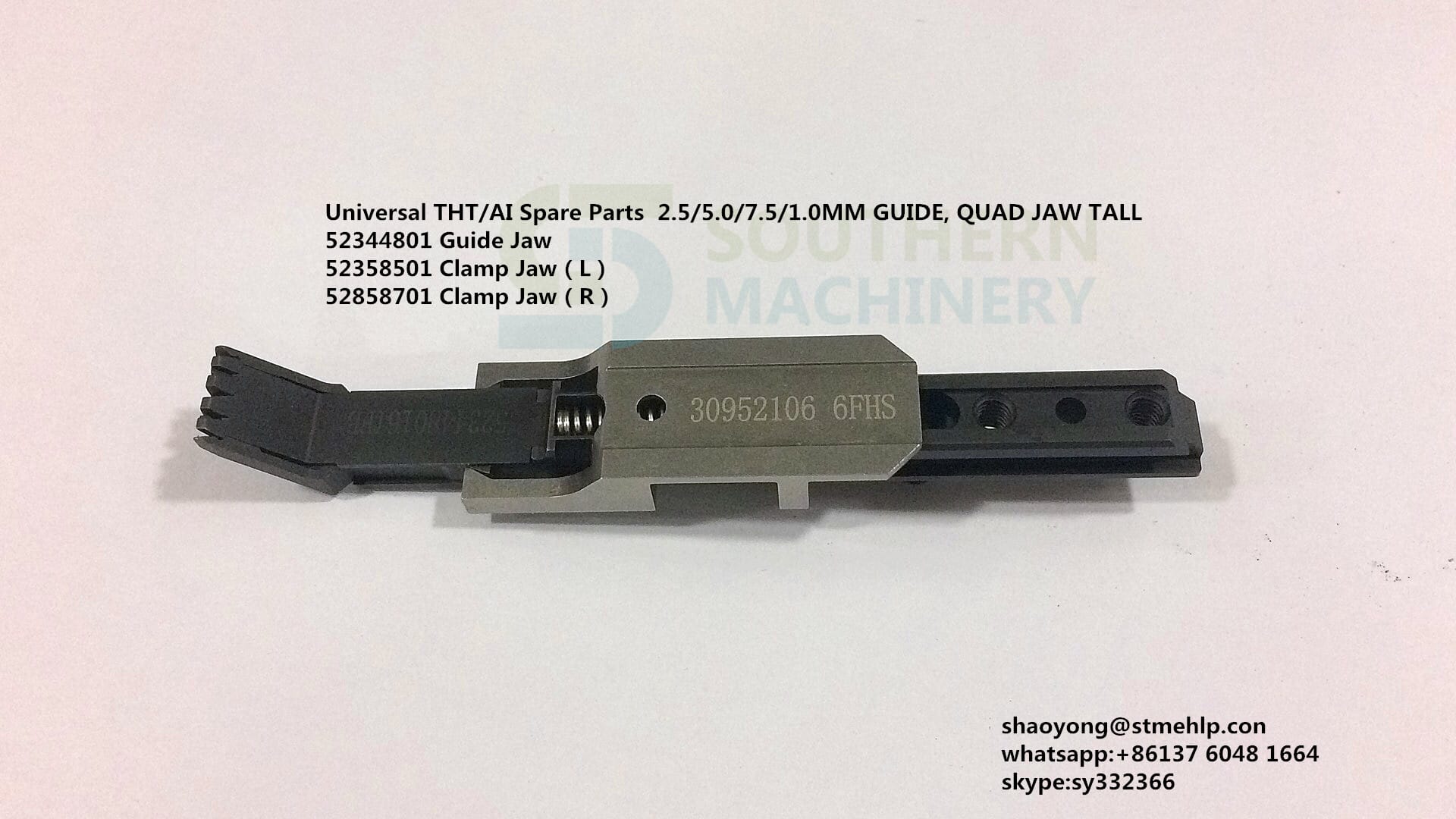
GUIDE JAW
1
544
44629606
JAW GUIDE
1
545
44629702
CLAMP JAW 10.5 MM
1
546
44629706
CLAMP JAW (13.0MM)
1
547
44629802
CLAMP JAW
1
548
44629902
CLAMP DUAL JAW 10.5 MM
1
549
44629906
1
550
44688804
AIR CYLINDER
1
551
44768402
MAC
1
552
44802801
740*5m*25w
1
553
44868502
COUPLING
1
554
44876902
SHAFT HEAD(6292-A)
1
555
44896001
BASE ADJUST
1
556
44896201
PLATE MTG
1
557
44896401
HOUSING
1
558
44896601
HOUSING
1
559
44896602
1
560
44896801
SUPPORT GUIDE
1
561
44896802
SUPPORT GUIDE
1
562
44896901
GUIDE BOTTOM
1
563
44896907
1
564
44897001
1
565
44909001
1
566
44906901
SWITCH P.B.MOM, 6292 D.H VCD, START, SINGLE ,ZERO,OVERRIDE, INSERT
Electronics are an integral part of our daily lives. Everything from our smart phones to our cars includes electronic components. At the heart of these electronics is the printed circuit board, also known as a PCB.
Most people recognize printed circuit boards when they see them. These are the small green chips covered in lines and copper parts you’ll find at the heart of gutted electronic devices. Made with fiberglass, copper lines and other metal parts, these boards are held together with epoxy and insulated with a solder mask. This solder mask is where that characteristic green color comes from.
However, have you ever observed those boards with components solidly stuck on? Never regard them as just decorations of a PCB board. An advanced circuit board won’t be able to give its functionality until components are mounted on it. A PCB with components mounted on is called an assembled PCB and the manufacturing process is called PCB assembly or PCBA for short. The copper lines on bare board, called traces, electrically link connectors and components to each other. They run signals between these features, allowing the circuit board to function in a specifically designed way. These functions range from the simple to the complex, and yet the size of PCBs can be smaller than a thumbnail.
So how exactly are these devices made? The PCB assembly process is a simple one, consisting of several automated and manual steps. With each step of the process, a board manufacturer has both manual and automated options from which to choose. To help you better understand the PCBA process from start to finish, we’ve explained each step in detail below.
The first step of PCB assembly is applying a solder paste to the board. This process is like screen-printing a shirt, except instead of a mask, a thin, stainless-steel stencil is placed over the PCB. This allows assemblers to apply solder paste only to certain parts of the would-be PCB. These parts are where components will sit in the finished PCB.Solder Paste Composition | PCBCart
The solder paste itself is a greyish substance consisting of tiny balls of metal, also known as solder. The composition of these tiny metal balls is 96.5% tin, 3% silver and 0.5% copper. The solder paste mixes solder with a flux, which is a chemical designed help the solder melt and bond to a surface. Solder paste appears as a grey paste and must be applied to the board at exactly the right places and in precisely the right amounts.
In a professional PCBA line, a mechanical fixture holds the PCB and solder stencil in place. An applicator then places solder paste on the intended areas in precise amounts. The machine then spreads the paste across the stencil, applying it evenly to every open area. After removing the stencil, the solder paste remains in the intended locations.
After applying the solder paste to the PCB board, the PCBA process moves on to the pick and place machine, a robotic device places surface mount components, or SMDs, on a prepared PCB. SMDs account for most non-connector components on PCBs today. These SMDs are then soldered on to the surface of the board in the next step of PCBA process.
Traditionally, this was a manual process done with a pair of tweezers, in which assemblers had to pick and place components by hand. These days, thankfully, this step is an automated process among PCB manufacturers. This shift occurred largely because machines tend to be more accurate and more consistent than humans. While humans can work quickly, fatigue and eyestrain tends to set in after a few hours working with such small components. Machines work around the clock without such fatigue.Surface Mount Technology | PCBCart
The device starts the pick and place process by picking up a PCB board with a vacuum grip and moving it to the pick and place station. The robot then orients the PCB at the station and begins applying the SMTs to the PCB surface. These components are placed on top of the soldering paste in preprogrammed locations.
Once the solder paste and surface mount components are all in place, they need to remain there. This means the solder paste needs to solidify, adhering components to the board. PCB assembly accomplishes this through a process called “reflow”.
After the pick and place process concludes, the PCB board is transferred to a conveyor belt. This conveyor belt moves through a large reflow oven, which is somewhat like a commercial pizza oven. This oven consists of a series of heaters which gradually heat the board to temperatures around 250 degrees Celsius, or 480 degrees Fahrenheit. This is hot enough to melt the solder in the solder paste.
Once the solder melts, the PCB continues to move through the oven. It passes through a series of cooler heaters, which allows the melted solder to cool and solidify in a controlled manner. This creates a permanent solder joint to connect the SMDs to the PCB.
Many PCBAs require special consideration during reflow, especially for two-sided PCB Assembly. Two-sided PCB assembly need stenciling and reflowing each side separately. First, the side with fewer and smaller parts is stenciled, placed and reflowed, followed by the other side.
Once the surface mount components are soldered in place after the reflow process, which doesn’t stand for completion of PCBA and the assembled board needs to be tested for functionality. Often, movement during the reflow process will result in poor connection quality or a complete lack of a connection. Shorts are also a common side effect of this movement, as misplaced components can sometimes connect portions of the circuit that should not connect.
Checking for these errors and misalignments can involve one of several different inspection methods. The most common inspection methods include:
• Manual Checks: Despite upcoming development trend of automated and smart manufacturing, manual checks are still relied on in PCB assembly process. For smaller batches, an in-person visual inspection by a designer is an effective method to ensure the quality of a PCB after the reflow process. However, this method becomes increasingly impractical and inaccurate as the number of inspected boards increases. Looking at such small components for more than an hour can lead to optical fatigue, resulting in less accurate inspections.
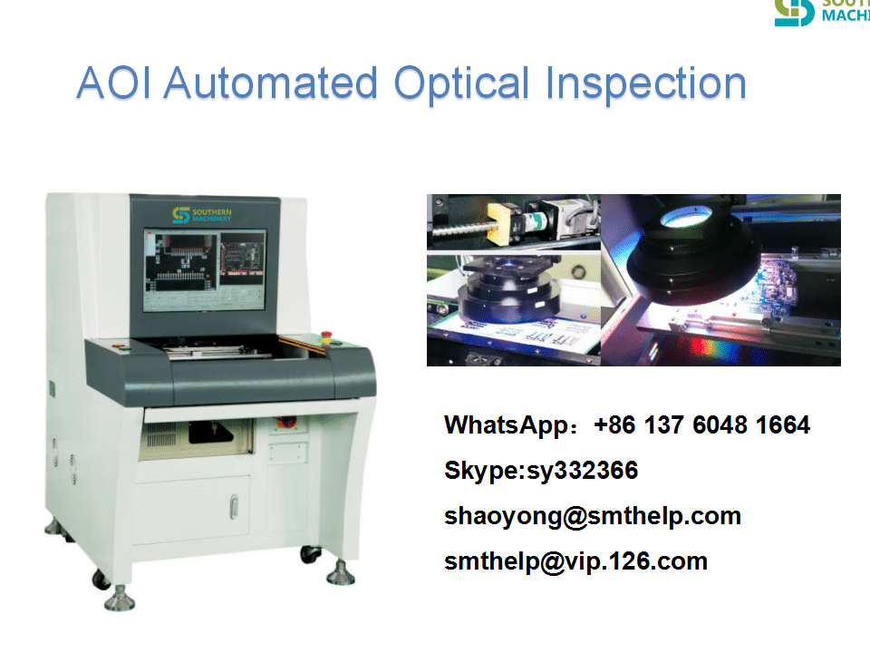
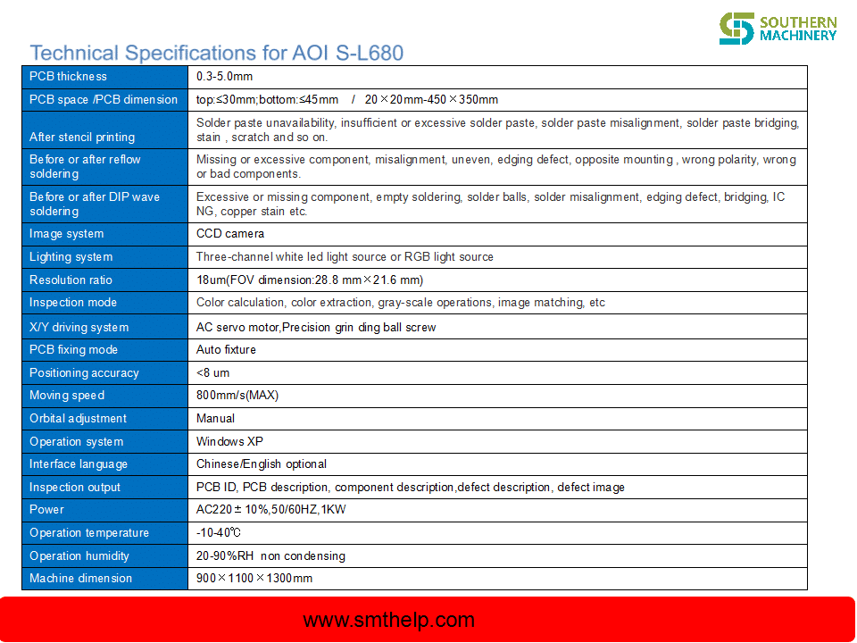
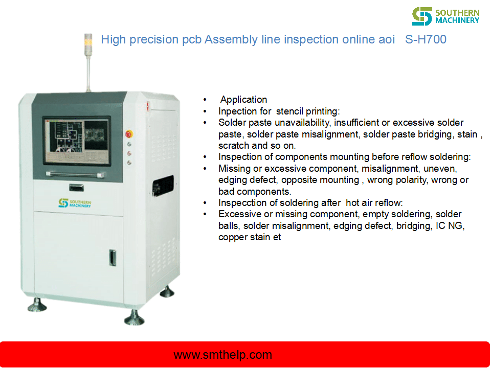
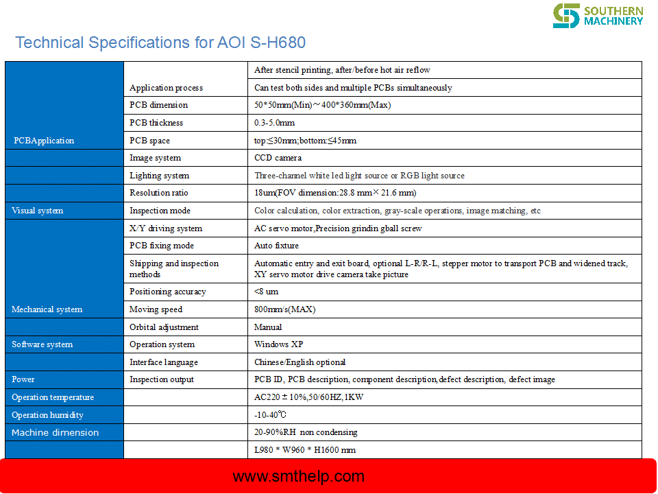
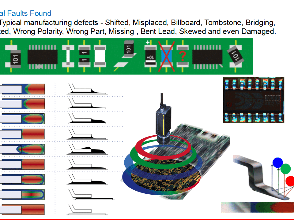
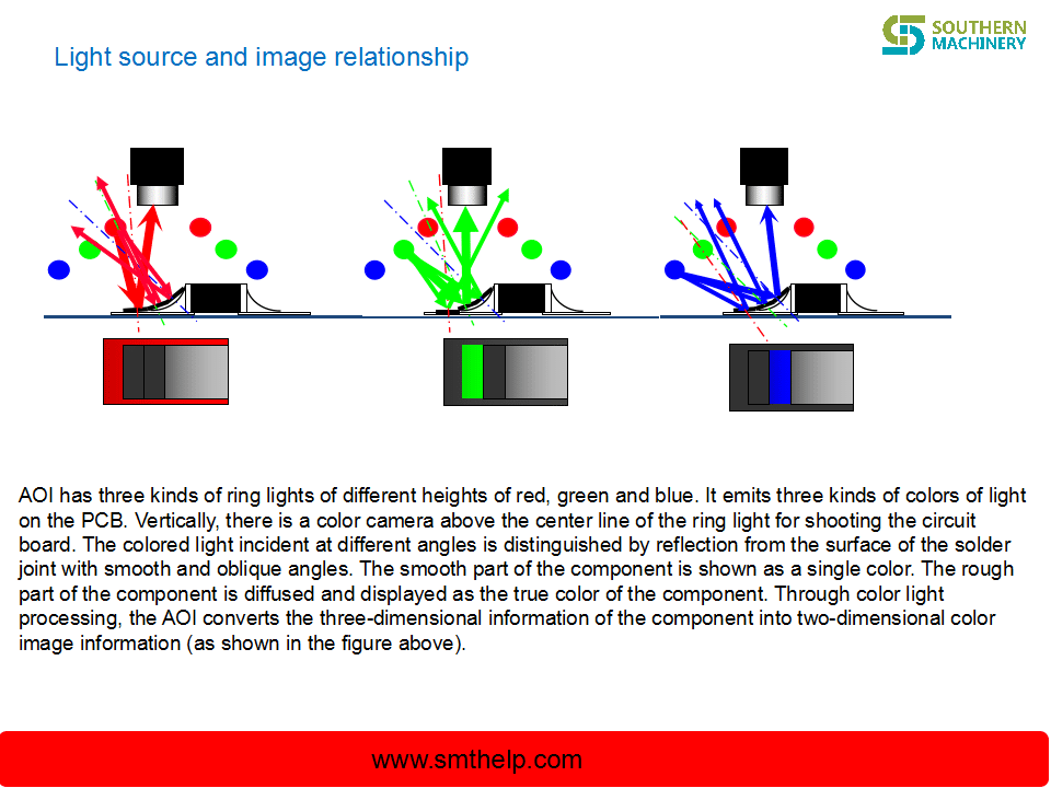
• Automatic Optical Inspection: Automatic optical inspection is a more appropriate inspection method for larger batches of PCBAs. An automatic optical inspection machine, also known as an AOI machine, uses a series of high-powered cameras to “see” PCBs. These cameras are arranged at different angles to view solder connections. Different quality solder connections reflect light in different ways, allowing the AOI to recognize a lower-quality solder. The AOI does this at a very high speed, allowing it to process a high quantity of PCBs in a relatively short time.
• X-ray Inspection: Yet another method of inspection involves x-rays. This is a less common inspection method — it’s used most often for more complex or layered PCBs. The X-ray allows a viewer to see through layers and visualize lower layers to identify any potentially hidden problems.
The fate of a malfunctioning board depends on PCBA company’s standards, they will be sent back to be cleared and reworked, or scrapped.
Whether an inspection finds one of these mistakes or not, the next step of the process is to test the part to make sure it does what it’s supposed to do. This involves testing the PCB connections for quality. Boards requiring programming or calibration require even more steps to test proper functionality.
Such inspections can occur regularly after the reflow process to identify any potential problems. These regular checks can ensure that errors are found and fixed as soon as possible, which helps both the manufacturer and the designer save time, labor and materials.
As a traditional PCB assembly method, thru-hole mounting process is accomplished through collaboration of manual procedure and automatic procedure.
• Step 1: Components Placement – This step is achieved manually by professional engineering staff. Engineers need to quickly, yet precisely place components on corresponding positions based on client’s PCB design files. Component placement must conform to regulations and operation standards of thru-hole mounting process to guarantee high quality end products. For example, they have to clarify polarity and orientation of components, to stop operating component from affecting ambient components, to make completed component placement compatible with corresponding standards and to wear anti-static wristbands when dealing with static-sensitive components like ICs.
• Step 2: Inspection & Rectification – Once component placement is completed, the board is then placed in a matching transport frame where board with components plugged in will be automatically inspected so as to determine whether components are accurately placed. If issues concerning component placement are observed, it’s easy to get them rectified immediately as well. After all, this takes place prior to soldering in PCBA process.
• Step 3: Wave Soldering – Now the THT components should be accurately soldered onto circuit board. In the wave soldering system, the board moves slowly over a wave of liquid solder at high temperature, approximately 500°F. Afterwards, all leads or wires connections can be successfully obtained so that thru-hole components are firmly attached to the board.
Compared with thru-hole mounting process, surface mounting process stands out in terms of manufacturing efficiency because it features a totally automatic mounting PCB assembly process from solder paste printing, pick and place and reflow soldering.
• Step 1: Solder Paste Printing – Solder paste is applied on the board through a solder paste printer. A template ensures that solder paste can be accurately left on correct places where components will be mounted, which is also called stencil or solder screen. Because quality of solder paste printing is directly associated with quality of soldering, PCBA manufacturers focusing on high quality products usually carry out inspections after solder paste printing through a solder paste inspector. This inspection guarantees printing has achieved regulations and standards. If defects are found on solder paste printing, printing has to be reworked or solder paste will be washed off prior to second printing.
• Step 2: Components Mounting – After coming out of solder paste printer, PCB will be auto-sent to pick-and-place machine where components or ICs will be mounted on corresponding pads in the effect of tension of solder paste. Components are mounted on PCB board through component reels in the machine. Similar to film reels, component reels carrying components rotate to provide parts to the machine, which will quickly stick parts to the board.
• Step 3: Reflow Soldering – After every component is placed, the board passes through a 23-foot-long furnace. A temperature of 500°F causes the solder paste to liquefy. Now the SMD components are bound firmly to the board.
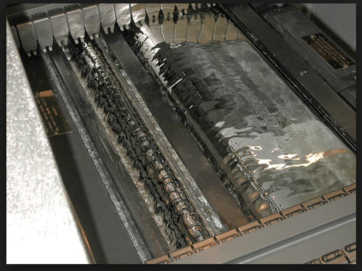
Wave solderingis a kind of solder wave with a specific shape formed on the surface of molten liquid solder by means of pump pressure. When mounted components pass through the solder wave at a fixed angle, solder joints are formed in the lead solder zone. The component is preheated in the preheating zone of the welding machine (the preheating of the component and the temperature to be reached are still controlled by the predetermined temperature curve) in the process of conveyor belt conveyor. In actual welding, the preheating temperature of the assembly surface is usually controlled, so many devices have added corresponding temperature detection devices (such as infrared detectors). After preheating, the components enter the lead slot for welding. Tin trough contains molten liquid solder. The nozzle at the bottom of the trough determines the shape of the solder. Thus, the solder wave is heated when the welding surface of the component passes through the wave. At the same time, the solder wave wets the welding zone and expands and fills the welding process.
wave soldering processwave soldering process
二、Basic working principle
Wave soldering is based on the principle of convection heat transfer to the welding area heating. The molten solder wave acts as a source of heat. On the one hand, it flows to wash out the pin welding area, on the other hand, it acts as a heat conduction. The pin welding area is heated under this effect. When the silver lead solder is used, the melting solder temperature is usually controlled at about 245 degrees Celsius. In order to ensure the temperature of the welding zone, the solder wave usually has a fixed width, so that when the welding surface of the component passes through the wave, there is sufficient time for heating and wetting. In traditional wave soldering, a wave is adopted and the wave is relatively flat. With the use of lead solder, double wave mode is adopted at present.
wave soldering pot
三、The welding spot
The pin of the component provides a way to immerse the liquid solder into the metal through hole. When the pin contacts the solder wave, the liquid solder climbs up along the pin and the hole wall with the help of the surface tension. The capillary action of metallized through-hole improves the climb of solder. When the solder reaches the PcB part, the surface tension of the pad is expanded. The rising solder discharges flux gas and air from the through hole, filling the through hole and forming a solder joint after cooling.
四、What’s the difference between wave soldering and reflow oven?
The mainly different are in heating source and solder supply mode. In wave soldering, the solder is pre-heated and melted in the trough. The solder wave pumped by the pump plays a dual role of heat source and solder supply. The solder wave of solder solder solder causes the through holes, pads and component pins of the PcB to be heated, and also provides the solder needed to form solder joints. In reflow soldering, solder paste is pre-quantitatively assigned to the solder zone of PCB. The role of heat source in reflow is to re-melt the solder.
五、Main components and working principle of wave soldering
A wave soldering machine is mainly composed of conveyor belt, heater, tin trough, pump, flux foaming (or spraying) device, etc. It is mainly divided into flux adding area, preheating zone and welding area.
The solder in the solder tank, heated by a heater, gradually melts, and the molten liquid solder, under the action of a mechanical pump (or electromagnetic pump), forms a specific shape of solder wave on the surface of the solder tank, which becomes a wave. The PCB with mounted elements is placed on the conveyor and solder joints are welded by passing through the solder wave at a certain angle and at a certain immersion depth, so it is called wave soldering.
For a single wave, there is only one wave, called the advection wave. For double waves, the first wave is called the disturbing wave, and the second wave is called the advection wave (Ping Huabo).
The role of spoiler: SMT element welding and prevent leakage welding, it ensures the proper distribution of solder through the circuit board. The solder is penetrated through the slit at a relatively high speed, thus leading to narrow gap. The direction of the jet is the same as that of the circuit board. For SMT components, the disturbance wave can basically be welded. But for through-hole components, the spoiler wave itself can not properly weld the components, it leaves the weld unevenness and excess solder, so the need for a second wave – advection wave.
The role of advection wave is to eliminate burr and weld bridge generated by the disturbance wave. Advection wave is actually the wave used by the single wave soldering machine. Therefore, when the traditional through-hole components are welded on the dual-wave machine, the disturbing wave can be turned off and the soldering can be completed by advection wave. The entire wavefront of the advection wave is basically horizontal, like a mirror. At first glance, it looks as if the tin wave is static, but in fact the solder is flowing continuously, but the wave is very smooth.
六、Wave soldering machine welding spot molding
Solder Joint Forming: When PCB enters the front end of the wave, the substrate and pin are heated, and before leaving the wave, the whole PCB is immersed in the solder, that is, bridged by the solder, but at the moment of leaving the wave end, a small amount of solder is attached to the pad due to the effect of wetting force, and due to surface tension, it will come out. At present, the shrinkage of the lead wire is small, and the wetting force between the solder and the pad is greater than the cohesion of the solder between the two pads. Therefore, a full, round solder joint will be formed, leaving the excess solder at the end of the wave, and due to gravity, it will fall back into the tin bath.
Bulk material handle method and process on SMT production line
SMT patch bulk material problems have plagued many SMT people, as we all know, once the placement machine starts, there will definitely be a problem in the SMT production line. For a variety of reasons, many bulk materials are produced, thrown, or are originally bulk materials, or other reasons. Some bulk materials, such as resistors, capacitors, inductors, etc., are not easily distinguishable and have little value in themselves, and there is no value for reuse. However, for large devices, especially some imported chip components, they are of high value and can be distinguished and distinguished, so they are generally reused. However, for scattered components, if the original package is a tray or a suitable tray, the problem may be solved better. Otherwise, it may be more difficult to handle. Southern Machinery today will talk about the handling of bulk material in the SMT production line. Method and process. First, the bulk material handle process
Collecting materials – material personnel sorting materials – using electrostatic bags to pack – paste material specifications – technicians based on bulk material springboard – hand paste bulk material – QC confirmation
Second, the definition
Bulk material: refers to the components that are separated from the original packaging during the production process due to machine throwing, or loading and unloading materials.
Third, job responsibilities
Material staff: responsible for the collection, classification, identification, storage, placement, and placement information of bulk materials, and the material loss rate is calculated according to the order.
QC in front of the furnace: responsible for the manual placement of bulk materials, the front back grain and material code confirmation, PCBA mark, and the classification of bulk materials.
Technician: Responsible for programming, patch production, monitoring patch quality distribution and timely improvement.
QC after the furnace: It is responsible for checking and checking the first piece of all the machines, and the quality is abnormal. Immediate feedback is provided to the front station to improve and track.
Fourth, the work content
In the production process, the material may be thrown due to equipment and other factors, so the operator should check the material step before the patch and after the shift, and check the throwing box and the trash can each time the garbage is dumped. Collect the bulk material and report to the supervisor about excessive bulk material anomalies.
According to the shape of the components, the bulk material is classified according to the shape of the components, and the back code of the components is checked to determine the material code. Then, the checked bulk materials are packed in anti-static bulk box or bulk bag, and the material code identification is performed to confirm the signature of the person. .
When using machine mounting, the operator should first check whether the components are consistent with the normal materials, confirm the material number, and then load the FEEDER tape.
The first piece of material feeding / mid-way refueling, the technician firstly inspects the materials that will be short of materials in the machine half-hour in advance, and collects the materials of the same item number in the component preparation area, and check them correctly, and submit them to the quality department QC/materials. The staff will check again and confirm the total signature of the refueling sheet.



-50595301-Clamp-Jaw(R.png)