How does SMT electronics assembly work?

Electronics manufacturing using surface-mount technology (SMT) simply means that electronic components are assembled with automated machines that place components on the surface of a board (printed circuit board, PCB).

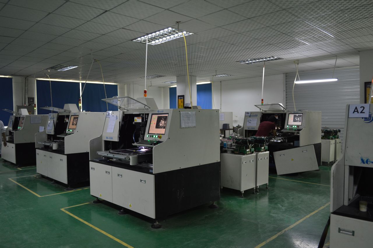
SMT车间

Electronics manufacturing using surface-mount technology (SMT) simply means that electronic components are assembled with automated machines that place components on the surface of a board (printed circuit board, PCB). In contrast to conventional through-hole technology (THT) processes, SMT components are placed directly on the surface of a PCB instead of being soldered to a wire lead. When it comes to electronic assembly, SMT is the most frequently used process in the industry.

Electronic assembly encompasses not only placing and soldering components to the PCB, but also the following production steps:

  • Applying soldering paste, which is made of tin particles and flux, to the PCB
  • Placing SMT components to the soldering paste on the PCB
  • Soldering the boards with a reflow process.

Applying Soldering Paste

Applying soldering paste is one of the first steps in the SMT assembly process. Soldering paste is “printed” on the boards using the silk-screen method. Depending on the design of the board, different stainless-steel stencils for “printing” the paste onto the board and various product-specific pastes are used. Using a laser cut stainless-steel stencil custom made for the project, the soldering paste to be applied only to the areas where components will be soldered. After the soldering paste is on the boards, a 2D-soldering paste inspection is performed to ensure that the paste is evenly and correctly applied. Once the accuracy of the soldering paste application has been confirmed, the boards are transferred to the SMT assembly line, where the components will be soldered.

AI spare parts、Universal Parts,UIC,TDK.VCD Sequencer.SMT,THT,PCB,PCBA,AI,wave soldering,reflow oven,nozzle,feeder,wave soldering,PCB Assembly, LED, LED lamp, LED display AI spare parts、Universal Parts,UIC,TDK.VCD Sequencer.SMT,THT,PCB,PCBA,AI,wave soldering,reflow oven,nozzle,feeder,wave soldering,PCB Assembly, LED, LED lamp, LED display

Component  Placement and Assembly

The electronic components to be assembled come in trays or reels, which are then loaded into the SMT machine. During the loading process, intelligent software systems ensure that components are not inadvertently switched or misloaded. The SMT assembly machine then automatically removes each component with a vacuum pipette from its tray or reel and places it on its correct position on the board using precise pre-programmed X-Y coordinates. Our machines are capable of assembling up to 25,000 components per hour. After the SMT assembly is completed, the boards are moved on to the Reflow ovens for soldering, which affixes the components to the board.

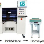
S-320 pick&place machine

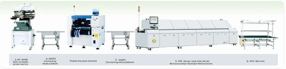
SMT line

Component Soldering

To solder electronic components, we use two different methods, each of which has distinct advantages depending on the order quantity. For series production orders, the Reflow-soldering process is used. During this process, boards are put in a nitrogen atmosphere and are gradually warmed up with heated air until the soldering paste melts and the flux vaporizes, which fuses the components to the PCB. After this stage, the boards are cooled off. As the tin in the soldering paste hardens, the components become permanently affixed to the board and the SMT assembly process is completed.

For prototypes or highly sensitive components, we have a specialized vapor-phase soldering process. In this process, boards are heated until the specific melting point (Galden) of the soldering paste is reached. This allows us to solder at lower temperatures or solder different SMT components at different temperatures depending on their individual soldering temperature profiles.

PastedGraphic-59

AOI and Visual Check

Soldering is the second-to-last step of the SMT assembly process. In order to ensure the quality of the assembled boards, or to catch and correct a mistake, AOI visual inspections are performed for almost all series production orders. Using several cameras, the AOI system automatically checks each board and compares the appearance of each board with the correct, pre-defined reference image. If there are any deviations, the operator of the machine is informed of the potential problem, who then corrects the mistake or pulls the board from the machine for further inspection. The AOI visual check ensures consistency and accuracy in the SMT assembly production process.

Dimensons_floor _layout - A_cmyk

Pay more attention to safety hazard during operating auto machine!

e4dde71190ef76c6420b6a0e9f16fdfaaf51673e (2)


Automation technique is applied to the development of mechanical manufacturing industry ,which  can greatly improve productivity, in other hands, the machinery manufacturing automation technology is currently one of the most valuable in the world of science and technology, it is to promote the development of social productivity and also make people’s life become more quickly, play an important role in improving people’s living standard.

But with the development of mechanical processing manufacturing, also can not avoid artificial operating machinery and equipment, and always heard the sad news, such as workers injury or death when operating the machine.On May 29, a factory ‘s worker body is stuck to the machine unfortunately when operating the machine, while firefighters rushed to the rescue, the women were taken to a hospital successful, but the last,the woman died of his wounds.This let us deep thinking.

So in our SMT/AI industry,every workers must to know the machine security issues and safety guidelines,it‘s very important,we must ensure the safety of workers!

SMT车间


 Security issues and  safety guidelines:

1 Tooling cuff requirements beam, work shoes should be prevented slippery, and can’t wear high heels.

2 When  working alongside the material stack, must press the STOP button bright women scarves.

3 The woman should on long hair to disk, and the men tie to close firmly, prevent into the machine at work.

4 Single machine operation, it is strictly prohibited to many people at the same time.

5 Hands in upper and lower, inside the machine components to use pliers or tweezers (axial element), hands, hands after leaving the plug-in area, then operate the control panel.

6  Must sure to remove all tools sundry machine worktable when start to operate the machine.

7 Work in it is prohibited to put any goods on the worktable, so as not to damage the machine.

8 In the work such as unexplained machine stopped suddenly, may not be reached below the plug-in head.

9 Plug-in mistakes in normal production, may not be reached to the head.

10 For the automatic machine, the machine in normal production, it is forbidden to reach into to send slab bridge.

11 To understand the mesa machine movement area, not collision.

Maybe there are more things we should care,safety is the basis of the production.So please every factory ’s leader pay more attention to the Security issues and the workers must be more care.


S600-OF SERIES AUTO INSERT&SURFACE MOUNTING MACHINE

S600-OF SERIES

AUTO INSERT&SURFACE MOUNTING MACHINE

The s-600-of is a revolutionary new concept from southern machinery.
that allows the placement or insertion of both http://tadalafiltablets.net surface mount
and through-hole components.

Nozzle: 6 PCS
?PCB Size:400*360mm
?Speed:12000-15000CPH

?Insert Object:Capacitor,Switch,
Connector, etc.
?Mounting Objet:Standard SMD
CLICK HERE TO SEND ME A EMAIL

Congratulation SOUTHERN MACHINERY has beed admitted as Foreign Member of ELCINA community

http://www.elcina.com

Electronic Industries Association of India identifies and bringstogetherlikeminded companies to represent the voice of Indian electronics and IT hardware industry and promote manufacturing.Electronic Industries Association of India promotes hardware manufacturing through active representation in the Government as well as scientific/technical institutions and industry/trade organisations in India and abroad.Electronic Industries Association of India represents to the government, problems faced by its members, individually or as a group, to find solutions and provide relief from unreasonable acts of administrative and policy making departments.

Electronic Industries Association of India provides a bouquet of professional and value-added services to its members. These services are tailored to serve the best interest of its Members and the Electronics/IT community to empower it to face competition and prosper. These services are constantly upgraded to suit the changing demands of the environment and needs of the industry.

Electronic Industries Association of India’s E-commerce facilities and its dynamic website together attract about 3500 visitors per day and provide a platform for members.

Electronic Industries Association of India is a repository of information and research, readily available for its members and helps them in taking critical decisions based on relevant facts.

Services currently provided by Electronic Industries Association of India to its members can be found by clicking here.

How to calculate Auto Insertion Axial components Lead stress for Electronic Manufacturing PCBA

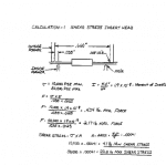
Our engineering group performed calculations of the stress induced on axial components during the forming and insertion process. Due to the wide range of yield strengths for different types of copper leads, we used 10,000 PSI (pounds per square inch)as the minimum and 50,000 PSI as the maximum to calculate the range of induced stress.

Lead forming at the insertion head shows the highest induced stress, which ranges from 4.1 pounds minimum, to a maximum of 20.5 pounds. (see calculation 1, below). Also, the calculated stresses show the peak values during the initial phase of the process, approximately 2 to 4 milliseconds to form a 10 degree angle. Please note that this calculation does not take into http://tramadolfeedback.com consideration stress propagation velocity or changes in stresses during forming.

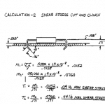
Lead forming at the Cut and Clinch shows significantly lower stresses than the lead forming process in the insertion head. At the Cut and Clinch, induced stress ranges from .09 pounds minimum to a maximum of .44 pounds (see calculation 2, below). Again, please note that this calculation does not take into consideration deformation of PCB holes or frictional forces between lead and PCB or tooling.

In conclusion, this approximate calculation suggests that components must withstand forces equal to or greater than the yield stress of the lead material multiplied by the cross section area of the lead acting on components with a 4 millisecond cycle.

AI spare parts、Universal Parts,UIC,TDK.VCD Sequencer.SMT,THT,PCB,PCBA,AI,wave soldering,reflow oven,nozzle,feeder,wave soldering,PCB Assembly, LED, LED lamp, LED display

2 video to compare Manual and Auto PIN/ Eyelet/Terminal insertion for electronic manufacturing PCBA

The Through Hole Assembly, also known as thru hole assembly, process uses the latest models with the quickest possible turnaround rate in the industry. Assembling excellent stable sequencing performance with easy operating software utilizing its high precision through hole assembly both by hand and automation to create electronic solder connections.


C (20121106 212843894) Audio003

Automatic PIN/ Eyelet/Terminal insertion:

ManualPIN/ Eyelet/Terminal insertion:

AI spare parts、Universal Parts,UIC,TDK.VCD Sequencer.SMT,THT,PCB,PCBA,AI,wave soldering,reflow oven,nozzle,feeder,wave soldering,PCB Assembly, LED, LED lamp, LED display

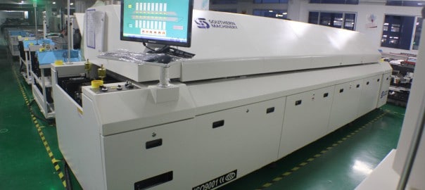
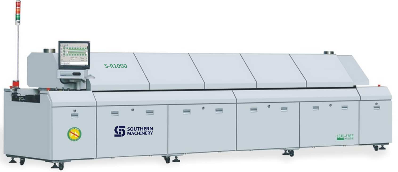
SMT Lead-Free Reflow Over S-R1000 for electronic manufacturing PCB assembly

AI spare parts、Universal Parts,UIC,TDK.VCD Sequencer.SMT,THT,PCB,PCBA,AI,wave soldering,reflow oven,nozzle,feeder,wave soldering,PCB Assembly, LED, LED lamp, LED display

CatchBDD7(02-01-(02-01-11-12-19)


Features:

1.Control System: PC + Siemens PLC control system,accurate temperature control and more stable,ensures temperature stability rate to be more than 99.99%.

2.Hot air system: first-class heating module, the best temperature zone interval design makes optimum temperature uniformity and repeat.The effective utilization and thermal compensation efficiency,it needs less than 20 minutes from temperature control accuracy ± 1 ℃ ambient temperature to a temperature stabilization .

3.Monitoring Software:Windows interface, traditional and simplified Chinese and English online free switch, and operator password management, easy to operate.Operation records, temperature curve measurement and analysis functions, virtual simulation, fault self-diagnosis, process monitoring, automatic generate and save process control documents, substrate transport dynamic display.

4.Cooling System: new cooling zone, quick and easy adjustment, easily reach the cooling requirements of different slopes.

5.Temperature protection: using third-party over-temperature protection, multiple layers protection to ensure safe operation.

6.Products comply with CE, CCC, UL , other standards and specifications.

7.User-friendly design: fault detection (such as heaters abnormal alarm, etc.), regular maintenance reminders, the economy functions and tool-free maintenance, reducing equipment failure rates.

8.Heating module: Transverse reflow design makes temperature from each zone is not influenced by neibour to ensure accurate temperature curve, while ensuring a high production capacity and heat exchange capacity to achieve high adaptability (to meet the soldering of automotive, communications, electronics, computers and mobile phones consumer electronics.)

9.Hot air motor with independently inverter controlled, set operating frequencies depending on different technology to meet a variety of lead-free processes.

10. Machine using zero gas source design, furnace cover with motor lifting, safety rod support, providing significant security.

11.Main parts:Imported main parts ensure equipment runs smoothly and lower the maintenance cost.

12. Customers can choose optional flux processing system according to their own production features  to ensure furnace chamber clean.

13.Closed-loop transmission speed control systems, transportation accuracy ± 2mm / min, ensuring more stable transmission speed.

14.Central support, dual transmission, external water cooling system is optional.

TOP Advantage:

1.Simple: combined with advanced international concepts, based on the Oriental-designed operating system, easy to understand, easy to learn, easy to maintain.

2.Expertise: learn imported reflow oven’s advanced design concepts, and the machine core components are using imported top brands.

3.Hedging: Import hardware configuration,low failure rate in production,more than a decade service life.

4.Safety: Based on the general rules of international design, close to imported reflow rating, the highest security level.

5.Stable: mature software, hardware and top production processes ensures stability of each equipment.

Application  

Widely used in high precision products like 01005-QFP, BGA, CSP, Flip,and POP ,automotive electronics, mobile devices, home appliances, communications, LED, semiconductor and other industries.

Specification:


Southern Machinery  Reflow Oven Specifications
S – Standard, O – Option, M – Manual, A – Auto, N/A – Not Availible)
Specifications S-R800 S-R1000 Specifications E8 E10
Dimension (L*W*H)mm 5310x1353x1490 6100x1353x1490 Board Dropped Alarm S S
Standard Color Computer Grey Computer Grey Electrical SMEMA Interface S S
Weight Approx.2150KG Approx.2400KG Computer Lenovo Lenovo
Number Of Heating Zones Up8/Bottom8 Up10/Bottom10 Max.Width Of PCB 400mm 400mm
Length Of Heating Zones 3121mm 3891mm Temperature Deviation on PCB ± 1.0℃ ± 1.0℃
Rail Width Adjustment A and M(Multi mode) A and M(Multi mode) Max. Temp. Gap Between Preheat Zones Setting 40℃ 40℃
Rail Number 1 Lane or 2 Land 1 Lane or 2 Land Temperature Control Precision ± 1.0℃ ± 1.0℃
Exhaust Volume 10M3/minx2 Exhausts 10M3/minx2 Exhausts Conveyor Height 900+/-20mm 900+/-20mm
Control System PLC+Computer PLC+Computer Length Of Cooling Zones 600mm 600mm
Transmission Agent  Chain + Mesh  Chain + Mesh Center Support O O
Electric Supply Required 3phase,380V 50/60Hz 3phase,380V 50/60Hz Siemens PLC S S
Power For Warm Up 30KW 36KW Lubrication Auto-Afflux S S
Power Consumption 8KW 12KW Ups S S
Warming Time Approx.25 minute Approx.25 minute Temp. Thermocouple Slot S S
Temp. Setting Range Room Temp.– 300℃ Room Temp.– 300℃ Driven Top Hood Opening A A
Oil Supply A and M(Multi mode) A and M(Multi mode) Temperature Control Method PID + SSR S S
Conveyor Speed Range 300~2000mm/min 300~2000mm/min Number of Cooling Zones 2 2
Components Clearance Top/ Bottom is 25mm Top/ Bottom is 25mm On Line Editing S S
Conveyor Direction L→R (Option: R→L) L→R (Option: R→L) Max.Temp.Gap Between Preheat & Reflow Setting 80℃ 80℃
Commutated Element Aluminum Alloy Plate (8mm) Aluminum Alloy Plate (8mm) Max. Temp. Gap Between Reflow Zones Setting 50℃ 50℃
Fixed Rail Side Front Fixed  (Option:Rear  Fixed) Front Fixed  (Option:Rear  Fixed) Process Data & Status Storage S S
Cooling Method Forced-Air Motor and fan (Standard) Forced-Air Motor and fan   (Standard) Temperature Alarm S S


Independent Upper and Lower PID Temperature Controls

Independent Upper and Lower PID Temperature Controls for Each Heating Zone Permit Precise Temperature Profiling

S-R1000’s heating zone temperature controllers have an accuracy of ±1°C and, in conjunction with a high-speed blower adjacent to each heat source for maximum convection, ensure a ΔT of ±2°C across the PCB assembly. The Series diffuser design provides low-velocity, low-turbulence air flow to prevent component shift or disturbance.

Optional thermocouples can be attached at critical locations on the PCB and connected to three built-in inputs (standard) on the oven for communication with  control software for accurate, real-time temperature profiling to match any solder paste manufacturer’s specifications.

CR-10000 SMT Reflow Oven Pin over mesh conveyor

Pin-Over-Mesh Conveyor Meets Virtually Any Product Specification or Production Requirement

The S-R1000 is supplied as standard with an adjustable-rail, pin-type conveyor system that handles PCBs up to a maximum of 450 mm (17.7″) installed over a 570 mm (22″) stainless-steel mesh belt. The pin conveyor permits inline and double-sided processing. The mesh belt is ideal for fast changeovers.

To eliminate the possibility of jamming or dropped PCB assemblies, all components are constructed of high-quality, high-strength, stainless steel and are built to maintain dimensional tolerances at the high temperatures of lead-free processing.

Advanced automatic chain lubrication and motorized width adjustment are standard features on the pin conveyor. Automatic width adjustment of the pin conveyor, based on the parameter settings for specific reflow programs, is available as an option. For processing of larger PCBs at higher lead-free temperatures, a center support system is available to prevent board warpage.

Conveyor speed is programmable from 400-1800 mm (16″-71″) per minute to accommodate any process requirement.

Nitrogen Atmosphere Compatible Models Widen Lead-Free Processing Window Through Reduced Oxidation

While the debate over air or inert reflow atmospheres continues, as an option, offers the S-R1000 in a nitrogen-compatible configuration for manufacturers who want the flexibility for soldering in both environments.

Most experts agree that the reduction of oxygen through the introduction of an inert gas (usually N2) will allow a wider process window and provide better solder joints through reduced oxidation. The enhanced flow design of the heating chamber in the S-R1000 nitrogen compatible system lends itself to efficient heat transfer and ensures low nitrogen consumption while maintaining O2 levels between 300-1000 ppm.

CR-10000 reflow oven internal water-chilled recirculating cooling system available

Internal Water Cooling Provides Maximum Control Over Critical Cooling Rates Required By Some Lead-Free Solders

Because the higher liquidus temperatures required by lead-free solders approach the limits of many SMT components and PCB assemblies, more aggressive cooling is often required to reduce peak temperature exposure times. Some recent studies also indicate that cooling rates have a significant effect on solder joint grain structure.

For these reasons, an internal water-chilled recirculating cooling system is available for the S-R1000. It allows users to alter cooling rates to meet solder paste manufacturers recommendations to a much greater degree than is possible with the exclusive use of air cooling.

CR-10000 reflow oven real-time profiling

Advanced Functionality and Process Management Capability

Operation and control of all  reflow systems is accomplished through an attractive, colorful, visual user interface that features a full-screen, virtual view of the system with display of pre-set and actual zone temperatures, system status and conveyor speed.

The Windows-based operating system and control software includes advanced functions for temperature profiling, timed automatic startup and shutdown, audible and visual alarms, and password protection.

A PC-controller with 15″ flat screen monitor, keyboard and trackball allow unlimited storage and networking capability.

All systems employ UPS battery backup to ensure removal of all product from the oven in the event of a power outage.

SMT,THT,PCB,PCBA,AI,wave soldering,reflow oven,nozzle,feeder,wave soldering

1 Video let you see what is auto insertion for electronic manufacturing Axial Component assembly

Axial Sequencer – The axial sequencer machine takes axial leaded through-hole components from reels and creates a tape chain of components in order of insertion for use on the axial insertion machine.


Component Lead Hole Guidelines

PCBs should be punched or drilled for component lead insertion to the following recommended hole diameters for optimum performance:

Hole Diameter = Lead Diameter + 0.48 mm (0.019 in.) ± 0.08 mm (0.003 in.)

Hole sizes:

• Less than recommended – Might result in reduced insertion reliability

• Greater than recommended – Might result in loose components in the PCB

Holes used for board error correction should be 1.0 mm (0.040 in.) ± 0.5 mm (0.020 in.). Plated holes or translucent PCBs might affect performance

AI spare parts、Universal Parts,UIC,TDK.VCD Sequencer.SMT,THT,PCB,PCBA,AI,wave soldering,reflow oven,nozzle,feeder,wave soldering,PCB Assembly, LED, LED lamp, LED display

One Video let you know how Radial Insertion works for Electronic through-hole components assembly

  • Radial Insertion – A radial inserter takes radial leaded through-hole components from reels and creates a sequence of components in order of insertion. Then the machine auto inserts the components into the PCB. The machine can be programmed to bend and cut leads per customer/component specifications.