How to improve SMT PCB assembly quality

MISPRINT CLEANING

INTRODUCTION

Assemblers surveyed report that cleaning misprinted circuit assemblies is a production gap that has not been adequately addressed. Traditionally, the industry has used stencil cleaning agents and equipment to address this rework need. One of the benefits of cleaning misprinted assemblies with the stencil cleaning process is the ability to collect and filter wet solder paste. The major short coming of cleaning misprints within stencil cleaning processes is the inability to remove B-side reflow flux residues from both the surface and under bottom termination components.


REWORKING/CLEANING MISPRINTED ASSEMBLIES

Stencil printing is a highly automated process. During machine setup, a small group of boards are misprinted. During production stencil printing, circuit boards are periodically misprinted due to clogged apertures, stencil out of alignment, solder paste rheology shifts and other issues. Stencil misprints are defined as A-Side (Initial print out of alignment with no components previously placed) and B-Side (A-Side was successfully printed and components placed and soldered. The subsequent process of printing the B-Side results in the solder paste being out of alignment resulting in a B-Side misprint).


Printed Circuit Board misprints are a costly problem with no easy rework methodology. Production cleaning processes are normally not used to clean misprint assemblies. Potential quality issues such as:

  • Solder balls collecting into the wash tank and being transferred back onto the assembly
  • Solder balls migrating into the rinse streams resulting in hazardous waste from metals in the wash and rinse holding tanks

These complexities potentially compromise repeatability and reliability standards. Due to these complex issues, most assembly houses do not allow misprints to be cleaned within their production cleaning process.


Assemblers commonly address the misprint cleaning need by either hand wiping the misprinted side of the circuit card and/or clean the misprint in a stencil cleaning machine. Both methods create the potential for quality issues. First, when wiping solder paste from the misprinted side of the board, solder paste can be trapped in solder mask defined channels, through-hole vias, and other board geometries (Figure 1). Numerous quality problems can result due to lack of control and definition.


Figure 1: Solder Balls Wedged into No Solder Mask Defined Channels and Via Holes


Second, stencil cleaning machines are designed to remove wet solder paste from stencils. Most stencil cleaning processes do not rinse the stencil with water. For those that use a water rinse, the water is reused since trace levels of metals in water prevent disposal to local treatment works. Cleaning a production board in a machine designed to clean stencils fails to meet ionic cleanliness standards required for a production assembly. Additionally, on B-Side misprints, the stencil cleaning agent is typically not adequate for cleaning reflowed flux residues on the A-Side of the board. In most cases, the stencil cleaning agent partially removes the reflowed no-clean flux residue resulting in white residue and an ionically dirty assembly.


FILTRATION OPTIONS

Cleaning the misprinted circuit board within an electronic assembly production cleaning process has the potential to achieve cleaning of wet solder paste and reflowed flux residues as well as meet quality and yield objectives. The problem with cleaning a misprinted circuit board in a production cleaning process is the deposits of solder spheres collected into the wash holding tank. Free solder spheres within the wash holding tank can be picked up by the inlet of the pump and sprayed onto production assemblies. There is also the potential that the solder spheres can be dragged into the rinse sections. Both quality and waste treatment issues result from this practice.

To resolve the quality and water treatment issues, collection and filtration method systems are needed to trap and filter solder spheres. Filtration systems designed tocontain the solder spheres and capture them prevents spraying solder balls through the pump and spray manifolds. The mechanical and filtration systems resolve the issues of redepositing solder balls onto production assemblies and the potential to contaminate rinse streams. The overriding quality advantages in using production cleaning equipment, which is designed for repeatedly removing all solder spheres from the assembly, remove reflowed flux residues and render an ionically clean printed circuit board provide a reproducible and repeatable product.

EQUIPMENT OPTIONS

Inline Cleaning Equipment

Two types of aqueous production machines are used to clean electronic assemblies, inline and batch. For the inline machine, the pre-wash section of the cleaning machine is designed to wet, elevate the circuit board to wash temperature, and soften reflowed flux residues from production circuit assemblies. On option for containing solder balls is to equip the pre-wash sectionwith deflectors that contain the raw solder paste as it is being displaced from the circuit assembly. The deflectors close in the pre-wash spray manifolds using two trays and plates to prevent solder spheres from escaping the housing of the pre-wash section. As the boards enter the pre-wash section, the displaced solder balls and wash fluid drain into the catch trays. By capturing and containing the pre-wash liquid, the majority of the solder balls can be channeled into a series of sluice boxes. This important design feature contains the bulk of the solder balls with a minimal amount escaping to the wash holding tank.


A series of Sluice Boxes can be designed to capture the heavy raw solder spheres similar to the techniques used in mining precious metals from water streams (Figure 5). Three separate sluice boxes capture the majority of the solder paste. Each sluice box is equipped with a wire mesh. The weight of the solder balls drop through the wire mesh and collect into the sluice box trays. The first sluice box captures the majority of the solder spheres with the remaining two sluice boxes used to collect the residual solder spheres.


Figure 3: Sluice Box Collection Boxes courtesy of Speedline Technologies

Solder balls that are not collected within the sluice boxes will drain into the wash fluid holding tank. To prevent these stray solder balls from being sprayed onto circuit boards, three pump intake strainers prevent large spheres from entering the pump (Figure 6). The smaller solder spheres that pass through the strainers will be captured in a bag filter from wash liquid pumped through the outlet of the pump.


Figure 4: Strainers in Suction Inlet of the Wash Holding Tank courtesy of Speedline Technologies

Following the suction strainers, the wash solution is pumped through a filtration system designed to collect any remaining solder spheres before reaching the spray manifolds. The wash outlet enters the top side of the filtration canister, exits the clean side of the filter and then goes to the spray jets.


Figure 7: Filtration Canister

Within the canister, there are internal bars that prevent the bag filter from getting next to the exit side of the filter housing. This design feature prevents back flow or resistance as the liquid pumps through the filter canister. The 10/5 bag filter cartridge (ten microns on the inside and 5 microns on the outside of the filter cartridge) provides double redundancy to contain any solder balls from escaping the filter (Figure 9). The 10 micron side captures the heavy particles and the fine 5 micron side of the filter assures no solder spheres are sprayed onto circuit cards. The filtration design removes solder balls as small as Type 5 Solder Paste while preventing solder balls going to the manifolds. Pressure drops are minimal due to the solder paste being captured within the bag filter. Should the pressure drop, the machine is equipped with a user defined interface, which sends an alarm to the operator. The design is such that thousands of misprint boards could be cleaned before having an impact on the bath integrity, pressure and cleaning performance.

Batch Cleaning Equipment

One main difference between batch cleaning machines versus an in-line type cleaner is the ability to program the type of wash cycle, the sequence, and cycle times within the cleaning process. It is therefore critical that the ability to effectively trap and collect wet solder paste be integrated into the batch cleaner wash cycles.


The design objective is to provide the board assembler the flexibility to deflux their normal production runs (A/ B side), deflux an A-side with B-side misprint, clean A/B side misprint, plus the ability to completely rinse and dry the product within the same batch type cleaner.

Similar to the design for the in-line cleaning system, the same equipment manufacturer used the multi-stage filtration approach to effectively collect solder spheres and to prevent the spheres from being sprayed onto the board assembly. A pre-wash type cycle in the batch cleaning process will wet, elevate the circuit board to wash temperature, and soften the reflowed flux residues from the production circuit assemblies. The flux composition with the raw solder paste is easier to remove than the reflowed paste. An internal bag type filter is used to capture the raw solder paste that is removed during the Flood Wash cycle . The main purpose of the internal bag filter is to minimize the amount of solder paste that would be drained into the wash fluid holding tank.


Figure 8: Bag Filter in Wash Holding Tank

Solder spheres that are not collected in the bag filter will collect in the wash fluid holding tank. To prevent large particles from entering into the wash pumps, two intake strainers are located in the wash holding tank.


Figure 9: Batch Intake Strainers

Following the suction strainers, the wash solution is pumped through a filtration system that is designed to capture the smallest of solder spheres before being sprayed through the wash fluid spray delivery system. The filtration system is designed to capture solder paste as low as type 5 paste (Figure 10).


Figure 10: Batch Filtration Design

SUMMARY

Cleaning both A-Side and B-Side misprints has been a complex problem for assemblers. Using a stencil cleaner to clean misprints has numerous flaws. Two key issues is the inability to remove reflowed flux residues with stencil cleaning agents and poor rinsing. Notwithstanding, most assembly houses do not allow misprints to be cleaned in production cleaning machines due to the risk of contaminating product boards with stray solder balls and due to waste water metal contamination issues.


Collection and filtration systems designed into inline and batch production cleaning equipment safely captures and contains solder spheres from being sprayed onto production assemblies. Additionally, the containment and filtration systems prevent raw solder paste from entering the rinse water streams.


Using a production cleaning machine provides numerous benefits to the assembler.

  1. Recovery and rework of expensive hardware
  2. Removal of wet solder paste
  3. Containment of solder spheres
  4. Removal of reflowed flux residues
  5. Exceptional rinsing
  6. Ionically clean assemblies
  7. Repeatable
  8. Reproducible


Wiping wet solder paste from production assemblies is a bad practice. When wiping wet solder paste, solder spheres can be wedged into no solder mask defined troughs, vias and other offsets. When these solder balls become wedged, high levels of energized sprays may not be sufficient in displacing a wedged solder ball.
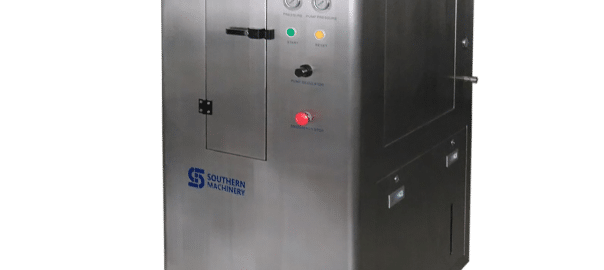
Optimal SMT stencil cleaning performance to improve Electronic Product Quality

Advantages of (2)

Powerful Cleaning Capability

Two ultrasonic cleansing head panels clear each the back and front sides of the metallic stencil concurrently. Ultrasonic power is utilized on to the stencil offering superior cleansing functionality.

Ease of Operation

Just press the beginning button and the method of cleansing and drying might be accomplished. No operator dealing with is required.

Low-VOC Cleaning Agent

Low-VOC cleansing agent, VIGON SC200 can be utilized for SC-AH100F-LV. There is not any flash level, low evaporation and virtually no odor. A good working setting might be maintained.

Reduction of CO2 Emission

reduces power consumption because of the shortened tact time and accordingly reduces CO2 emissions.

Cleaning Evaluation


Advantages of (2)
Powerful cialis Cleaning Capability

Two ultrasonic cleansing head panels clear each the back and front sides of the metallic stencil concurrently. Ultrasonic power is utilized on to the stencil offering superior cleansing functionality.

Ease of Operation
Just press the beginning button and the method of cleansing and drying might be accomplished. No operator dealing with is required.

Low-VOC Cleaning Agent
Low-VOC cleansing agent, VIGON SC200 can be utilized for SC-AH100F-LV. There is not any flash level, low evaporation and virtually no odor. A good working setting might be maintained.

Reduction of CO2 Emission
reduces power consumption because of the shortened tact time and accordingly reduces CO2 emissions.

Cleaning Evaluation

Who is one of the SMT solution provider for Global customers


initpintu_副本


Who is one of the SMT solution provider for Global customers, we can supply Automatic Insertion machines spare parts, SMT spare parts, (including feeder ,Nozzle,PCB board,feeder parts,motor,laser,feeder bank,feeder calibration jig ,ect)

main Service:

* Supply SMT/ AI spare parts.

* Supply SMT relate equipment.

* Supply SMT ancillary products and tools.

* Repair Service.

Contact me for more details:

Tel/WhatsAPP:(+86) 17773027293

Email: jessica@smthelp.net ;

Skype: Jessica SMT Sales


Are you finding the automatic nozzles cleaner?We can provide!

nozzles cleaner

In the process of SMT, the suction nozzle is quite easily adhered with solder paste or dirt etc. If maintenance has not been done for a long time or the cleaning is not thorough enough while maintaining it, the paste and dirt will be hardened so as to increase the difficulty of cleaning, even it will result in blockage and scraps after long-time accumulation. It practically proves that the S-U24cleaning machine can effectively deal with inflexible solder paste and thoroughly clean the suction nozzle with complex structure.


Equipment size     L× W×H (mm) 505 ×570 ×500
Equipment weight quality 70KG
Cleaning liquor   Cleaning liquor type Industrial purify water
consumption 400CC/H
Liquid used Air source Compressed air
Pressure range 0.5 -0.6Mpa(While cleaning)
Jet pressure 0.4Mpa
Air consumption 280NL/min.or less
Power Voltage AC200-240V
Rated power consumption Max. 200W
Suction nozzle tray Specification Default 24 positions
Object to be cleaned Mounting nozzle  01005-2125

What is the NEXT of Through Hole Technology in Electronic Manufacturing


We designed and manufactured Auto Insertion machine in Shenzhen China,  -- Decreasing labor cost  -- Easier manufacturing and operations management  -- Predictable Product Quality – Less repairs  -- No wrong parts nor wrong polarity  -- Less risk of damage due to human contact (contamination, ESD, physical damage to components)  -- Better clinching, less risk of solder issues.  -- Smaller factory space required to produce same volume of product

Welcome to visit Through Hole Technology Channel: https://www.youtube.com/channel/UCXvX1BREsZIKMSFBXKVGCCg

One way to insert Through Hole Components by SMT Pick and place machine

KEY WORDS
Solder Preforms, Pin-In-Paste, Intrusive Reflow, Mixed Technology, Selective Wave Soldering.

We design and manufacture An Auto Insertion machine:

1,Fully automatic PCB loading same as SMT gantry platform

2, One machine can handle both axial and radial lead components

3, Simply operation

4,Quickly production changeover.

5,Feeder slots : 10

6, No need cut and clinch

7, High density.


What is First Article Inspection

First Article Inspection overview

Before the manufacturing course begins, business necessities require an in depth verification and comparability of product design vs. manufacturing outcomes, often called First Article Inspection (FAI). Frequently used within the aerospace, medical electronics and automotive industries, FAI studies have gotten an ordinary course of to make sure high quality and consistency of the ultimate product is in order. Although conducting FAI could be advanced, technological developments and person pleasant software programs have allowed customers to implement and execute this course of shortly and precisely.

What is First Article Inspection?

As an official authentication technique for production, FAI intention is to overview and authorize dimensional studies. FAI stories make the most of dimensional properties of a manufacturing like design specs, to make sure of consistency or uncover any deviations. This inspection ensures reliability and repeatability of the manufacturing course, in addition to making certain the producer’s capability to provide elements in accordance with specifications.


What is the aim of FAI?

The goal of a FAI report outlined below:

  1. The FAI report supplies a tenet for goal affirmation that every engineering design and specification is appropriately understood, accounted for, verified and documented.
  2. Ensure the manufacturing course of action is dependable, repeatable and constant
  3. Develops a transparent understanding and communication outlet between purchaser and provider.
  4. Verify the accuracy of drawings, making certain that each adjustments made to any part of the designs are accounted for.
  5. Validate all tooling used for production, guaranteeing the instruments’ capabilities to supply all required elements at defined and accepted speed.
  6. Ensure manufacturing course is succesful and might meets the entiretly of all manufacturing needs.

When is FAI report crucial?

FAI studies are crucial when any of the following occur:

  • A change in design which may probably have an effect on match, kind or operation
  • A change in manufacturing supply, course of action, inspection technique, location of producer, tooling or supplies
  • A change to a special media program that will likely have an effect on match, kind or performance
  • Production has not been executed for 2 years or more (or as specified by buyer)

FAI Benefits

Before proceeding with manufacturing elements, FAI studies will be helpful in figuring out whether or not a production course of action is able to deliver elements constantly within design parameters. Furthermore, FAI studies present construction between buyer and provider for understanding and verifying the final mission necessities. FAI additionally assists buyer and provider with communications and help to avoid future miscommunication. This course of action additionally ensures that you will be using the precise supplies and instruments, offering an efficient initiative for the anticipated outcomes for manufacturing.

Full FAI vs. Partial FAI

A full FAI requires that each field has been accounted for.  With a partial FAI report, any subject missed will affect the FAI sucess. In regards to any excellent fields, they might be crammed out at a later date or utilizing earlier knowledge, on condition that it applies to the precise traits of duplicate elements produced by the identical manufacturing course of action.

FAI Planning

Before the primary manufacturing beings to run elements, many components have to be accounted for with the intention to execute FAI planning, which generally embrace the following:

Records for the manufacturing course of action– manage actions to be executed all through FAI course of and accountable suppliers/organizations.

Ensure authorized  materials sources, laboratory and relevant manufacturing, planning, routing and buying are in accordance with the specifications.

Save

One key point to consider Radial machine spare parts design and manufacturing

Reels or ammo packs of radial leaded components are loaded on the sequencer module, dispensed, and inserted in the PCB following the programmed sequence. Component dispensing heads remove components from the carrier tape and place them in component carrier clips located on the sequencer chain assembly. The sequencer chain assembly transports the components to the insertion area. While the components are on the sequencer chain assembly, the carrier tape is removed. The component transfer assembly transfers components from the sequencer chain assembly into the insertion head tooling. The insertion tooling guides the leads through the holes in the PC board. The cut and clinch unit cuts and then forms the leads, securing the component in the PC board.

Pay more attention to safety hazard during operating auto machine!

e4dde71190ef76c6420b6a0e9f16fdfaaf51673e (2)


Automation technique is applied to the development of mechanical manufacturing industry ,which  can greatly improve productivity, in other hands, the machinery manufacturing automation technology is currently one of the most valuable in the world of science and technology, it is to promote the development of social productivity and also make people’s life become more quickly, play an important role in improving people’s living standard.

But with the development of mechanical processing manufacturing, also can not avoid artificial operating machinery and equipment, and always heard the sad news, such as workers injury or death when operating the machine.On May 29, a factory ‘s worker body is stuck to the machine unfortunately when operating the machine, while firefighters rushed to the rescue, the women were taken to a hospital successful, but the last,the woman died of his wounds.This let us deep thinking.

So in our SMT/AI industry,every workers must to know the machine security issues and safety guidelines,it‘s very important,we must ensure the safety of workers!

SMT车间


 Security issues and  safety guidelines:

1 Tooling cuff requirements beam, work shoes should be prevented slippery, and can’t wear high heels.

2 When  working alongside the material stack, must press the STOP button bright women scarves.

3 The woman should on long hair to disk, and the men tie to close firmly, prevent into the machine at work.

4 Single machine operation, it is strictly prohibited to many people at the same time.

5 Hands in upper and lower, inside the machine components to use pliers or tweezers (axial element), hands, hands after leaving the plug-in area, then operate the control panel.

6  Must sure to remove all tools sundry machine worktable when start to operate the machine.

7 Work in it is prohibited to put any goods on the worktable, so as not to damage the machine.

8 In the work such as unexplained machine stopped suddenly, may not be reached below the plug-in head.

9 Plug-in mistakes in normal production, may not be reached to the head.

10 For the automatic machine, the machine in normal production, it is forbidden to reach into to send slab bridge.

11 To understand the mesa machine movement area, not collision.

Maybe there are more things we should care,safety is the basis of the production.So please every factory ’s leader pay more attention to the Security issues and the workers must be more care.


35000 CPH ! High Speed SMT pick&Place machine

 S-520 Pick&Place machine
Thickening marble platform,No shaking when working? guarantee the fuselage stability and accuracy !
Core motor adopts imported servo motor, 35000 CPH !
PCB max size: 1200 * 390, meet the demand of market LED diversity !

http://mentalhealthdrugs.com pick&place machine ” href=”//www.slideshare.net/XiaochanLiang/s520-pickplace-machine” target=”_blank”>S-520 pick&place machine from Liang Chan
SMT line
Provide SMT whole line solution

Do you really know how to build a SMT dust-free workshop in LED solution?

Before manufacturing led lights, it’s very important to conduct SMT factory planning, especially for any newly-built SMT factory. New factories have little experience in SMT factory design layout and SMT workshop design so there may be some details lost during the set-up phase. After production begins, discovering problems after the fact can cause unnecessary losses. So why not design your SMT factory layout and plan with these potential issues in mind and prepare in advance? Learn SMT clean mounting workshop production requirements in this article.

LED SMT车间

 SMT workshop production requirements:

1. Workshop bearing capacity, vibration, noise requirements:
Factory ground bearing capacity should be greater than 8 kn/m2.
Vibration should be controlled in less than 70 db, the maximum value of no more than 80db.
The noise should be controlled within 70 dba.
2.  Power supply:
General requirements of single-phase AC220 (220 + / – 10%, 0/60 hz), three-phase AC
380 (380 + / – 10%, 50/60 hz), more than double the power consumption of power supply of power than.
3. Air:
According to the requirement of the equipment configuration of air pressure, can use plant air, and  also be configured individually oil-free compressed air machine, general pressure is greater than 7 kg/cm2.
For clean, dry cleaning the air, so the need for compressed air to oil, dust and water treatment.Made from stainless steel or pressure plastic air duct.
4. Exhaust:
Reflow soldering and wave soldering equipment need exhaust fan.For hot blast stove, exhaust pipe of the minimum flow rate value is 500 cubic feet per minute (14.15 m3 / min).
5. Lighting:
In the ideal of the plant Illumination is 800 ~ 1200 lux, at least not less than 300 lux, when low intensity of illumination, in the inspection, repair, measurement work areas should install local lighting.

6. Work environment:
Factory to keep clean, no dust, no corrosivegas.Production workshop should have cleanliness control, control the cleanliness: the class of 500000.
Production workshop environment temperature to 23 + / – 3 ℃ is the best, average of 17 ~ 28℃,relative humidity is 45% ~ 45% RH.

Save