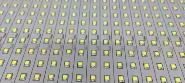
Southern Machinery provides professional SMT peripheral equipment

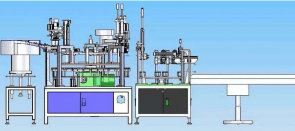



Why SMT? How to EMS?
Why SMT?
Manufacturers continuously evaluate new components and systems technologies in terms of reducing size, increasing design flexibility, improving reliability and reducing cost for systems. SMT satisfies all these requirements. It can provide size reductions of over 40%, assembly cost reductions of almost 50%, and can enhances the performance of electrical circuitry [Lea, 1988].
SMT Reduces Size and weight
The increased density of components can lead to a higher functionality in the same space. This allows the system manufacturer to price differentiate his product in the market by carefully choosing his components.
- SMT components require less circuit board area and volume than their through-hole equivalent.
- Components can be mounted on both sides of boards.
- Lighter components with the same functionality can be significant in the
aerospace industry as well as portable consumer electronics.
SMT Increases Performance
- SMT offers better interconnectivity due to shorter paths, providing lower inductance and capacitance.
- SMT reduces the package propagation delay, which is the time the signal needs to move from one component to another. Typically the longest delays in the system are off-chip.
- Electromagnetic interference can be decreased by combining sensitive circuits on a single board and improving its Electromagnetic Induction (EMI) shield design.
SMT Improves Reliability
- The smaller and lighter construction of SMC’s allow them to resist shock and vibration better than their through-hole counterparts.
- The reduced number of PCBs and connectors improves overall reliability at the system level.
- However, SMT systems require careful attention to mechanical design to avoid overstressing the solder joints.
- The demanding nature of the SMT process has resulted in extensive automation and corresponding increases in product quality.
-
SMT Reduces Cost
• Bare Boards
The use of SMT, typically, results in smaller area PCBs being used due to the reduction in the size of the components being used. In general for two functionally equivalent PCBs, one utilizing surface mount and the other using conventional through hole, the larger the PCB, the more expensive it will be. Increased density on an SMT board generally requires multiple layers as well as smaller line widths and spacings to accommodate the finer pitch components and smaller hole diameters to interconnect the layers. The only time a hole is required is to carry the signal to another layer whereas with through hole components there must be a hole for each lead of each component. In some cases through hole PCB’s may require more layers because there are more larger holes which means there will be less room on the inner layers for circuit routing increasing the layer count.• Processing
Surface mount components have almost all been designed for automatic assembly. Many unusually shaped, through-hole components, called odd- formed components, which were designed for hand assembly, can now be placed automatically as well. Automated assembly of surface mount assemblies can be done using one flexible automated placement machine whereas several machines may be required for the various through hole components.
As more types of components become available in a surface mount format, correspondingly fewer components are available in through-hole configuration forcing the cost of many SMC devices down. While through-hole components can be automatically inserted, the combined equipment, floor space and processing costs are higher.
• Factory Operating
Fewer types of assembly machines are required for an SMC assembly line and they often requires less floor space. Automated SMT assembly lines are considerably more productive than PTH assembly tools. Thus throughput is raised considerably with SMT manufacturing and the cost per unit of assembly is greatly reduced.
SMT Increases Flexibility
- SMT provides a wider range of packaging possibilities than insertion mount technology.
- SMT allows for the use of both surface mount and insertion mount devices in the same assembly.
SMT Eases Handling And Storage Space Needs
Surface mount components are easy to handle due to the various storage formats in which they are shipped and presented to the pick and place machines. Tape and reel, cartridge, sticks, magazines, and matrix trays allow effective and safe handling and shipping. The storage formats have the following features:
- Large number of components per packing unit resulting in less frequent loading of the tools.
- Small amount of packing materials per component resulting in lower shipping and inventory costs.
- Protection against transport and handling damage.
- Standardization, Definite orientation of the components.
- Protection against electrostatic discharge resulting in fewer defective systems
and rework.
- Compatible with highly automated equipment.
Electronic Industry Organizations and Groups
Uniform Standards for Surface Mount Technology are still under development in the USA, Europe and Japan. Although much has been accomplished, there is still no single set of industry guidelines. However, efforts are being taken to resolve this problem. For example, there was inconsistency in the standards set by the IPC and the EIA. As this was recognized, they have joined forces to set up a council called Surface Mount Council, to coordinate the various standards between the users and the developers of these standards. These documents have a J-STD- xxx designation. Moreover, other organizations like the International Microelectronics and Packaging Society (IMAPS) are working together on the technical issues in the PCB industry. These developments are promising and should lead to a common industrial standard in the near future.
IPC- Association Connecting Electronics Industries
2215 Sanders Road Northbrook, IL 60062-6135 USA Tel: (847) 509-9700 Fax – (847) 509-9798
Internet: www.ipc.orgIn 1999, IPC changed its name from Institute of Interconnecting and Packaging Electronic Circuits to IPC. The new name is accompanied with an identity statement, Association Connecting Electronics Industries.
IPC started in 1957 as the Institute for Printed Circuits. As more electronics assembly companies became involved with the association, the name was changed to the Institute for Interconnecting and Packaging Electronic Circuits. In the 1990s, most people in the industry could not remember the name and/or didn’t agree on what the words in the name meant. In addition, the leaders from government or other business groups could not understand the name either.
Ensuring the Best Design for Final PCB Production Stage with Testing!
Ensuring the Best Design for Final PCB Production Stage with Testing! Ensuring the Best Design for Final PCB Production Stage with Testing!
Avoiding Design Mistakes with Testing
Improve EMS Productivity by Testing Early

PC Board errors are a drain to EMS productivity. Through analysis and testing PCBs in the pilot stages, a smoother and more educated production set-up can be achieved. By performing automatic impedance measurements and testing of components (chip resistors and capacitors) early on, you can ensure the best design for production.
We recommend applying the best design logics when creating your PCB layout and Test, Test, Test for maximum efficiency and output. According to Circuits Assembly’s December 2016 Magazine, here is the list of 5 Most Common PCB Design Mistakes: “1. The components do not suit the production technology 2. Thermal imbalance 3. Incompatibility between fabrication and assembly technology 4. Component placement at PCB edge 5. Placing fiducials on the PCB’s edge.”
Once you have planned your PC Board with best practices, Southern Machinery’s High-Speed In-line Circuit Board Test Machine will help with testing by incorporating a visual inspection function which allows mounting status checks on each component (e.g.: typo descriptions in alphanumeric characters, orientation, size) on the operator’s monitor will serve to best analyze testing up close. As well as automatically generating test data from mounting data and component list.


Stop Importing & Start Automating!
Automatic Insertion Equipment Manufacturer for PCB Assembly
Stop Importing Cell Phones, Automate Them!
Times have officially changed. Where once there was no reason to invest in your homegrown cell phone manufacturing, now, with equipment that is more affordable than ever before, it makes sense to invest at home. Cell phone suppliers don’t have to rely on other countries to import cell phones any longer with new Smart Factories that are more efficient and affordable than labored hands. Now, businesses can incorporate manufacturing into their business model, and finally stop importing from China.
The SMT, pick and place Industry has revolutionized the way we used to look at manufacturing. The reasons for importing cell phones from China, namely cost and labor, are being reduced with the advancement of PCB AI Assembly equipment. Now you can home-grow your cell phone manufacturing with equipment that is smarter, faster, efficient, and more affordable than human labor force.
These huge changes will affect all companies that rely on electronics manufactured abroad. These imported items that have been historically low in cost, will no longer have the same low price tag. Intelligent companies are staying ahead of the curve and beginning to create their own reliable manufacturing processes, IN-HOUSE.
The good news is that there are companies that have planned ahead. It is now easier than ever to begin or improve your own manufacturing capabilities. It is not the huge undertaking it once was to establish and expand your own manufacturing equipment. PCB AI Assembly equipment is smarter, faster, efficient, and more affordable than ever before. Now is the time to get on board!
We have your solution! Become an Industry Leader!


Your PCB Assembly Quality Checklist ✏
We have EVERYTHING you need…
Your PCB Assembly Quality Checklist

 After many requests, we are thrilled to announce our Industry Leader Newsletter. As an Industry Leader, Southern Machinery wants to provide your company with the same excellence we put into our equipment and services. We know your job is important and you must always stay ahead of trends in PCB Assembly. Changes in labor costs, shifting environmental laws and policies, energy conservation efforts, advancing industries, international trade politics, etc., are causing a reemergence of in-house manufacturing systems to be put into place. The tide has shifted and it is now time to begin transitioning to a more self-sufficient manufacturing system.
Welcome to our smthelp.net Newsletter! No matter what your company role is, this Newsletter will keep you up-to-date with the most important topics and events that affect the quality and profitability of your manufacturing systems. If it has been a while since we last spoke, stay tuned! We will be delivering important PCB topics to your inbox. In the meantime, we have put a quality checklist together for you!
Your Manufacturing Quality Checklist here:
- Do you have ROI-Driven Design and Implementation of reliable PCB Assembly Equipment?
- Is your equipment Low-Cost with High-Intelligence?
- What is the speed of your PCB throughput?
- Is your efficiency high?
- Is your productivity high?
- Are you increasing your profits by using affordable and reliable equipment?
- Is your short-term investment low?
- Is your long-term investment low?
- Have you eliminated hand insertion for Automatic Insertion for improved time and profits?
- Finally, have you eliminated your import fees by producing your own PCBs?
Share this Entry
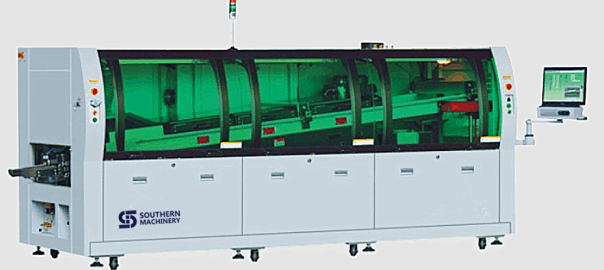
Welcome home — Shenzhou XI and Congratulations on Southern Machinery’s Wave Soldering machine successful ship out to overseas
Today, the Shenzhou XI spaceship will come back to the Earth after a monthlong mission in the space.
Find below video channel and know how China made SMT AI machine.
1,SMT pcb assembly LED
https://www.youtube.com/channel/UClX0iEG2bvJq8yUBEDamgDw
2, Through hole technilogy
https://www.youtube.com/channel/UC6Pj74wjjEjtp-jneRoSL9Q
3,SMT Machine For PCB Assembly
https://www.youtube.com/channel/UCke0s_OM0eKflD8WmGSLm5A
4,Odd Form Insertion Machine/Feeder
https://www.youtube.com/channel/UCactVXP8IrU3l-vItOODRCA
https://www.youtube.com/channel/UCMuFHjsSuaIXnc3_3yNcwzw
6, Stencil Cleaner Machine Southern Machinery
https://www.youtube.com/channel/UCnMRyXlBFqJZHYuqaZVoK4Q
7, LED Mounter
https://www.youtube.com/channel/UC4Z_P3S6qAYLHnlE-DU2OSA




UIC SMT machine PEC Camera Assembly – T50319001 Rev
| Beam 2 FW PEC Camera Assembly – T50319001 Rev. K |
| This Document Supports Assembly 50319001 Rev. G |

Replace the PEC Camera Assembly
If the PEC Camera Assembly is damaged or experiences an electrical or optical failure, the camera must be replaced.
|
|
CAUTION |
| Use caution when handling the PEC Camera and Lighting Assemblies. These assemblies are very sensitive to sudden shock. Also use ESD precautionary measures when handling the PEC Camera and Lighting Assemblies. A properly grounded ESD wrist strap is recommended. |

Prerequisites
Make sure that the following items are available before beginning the procedure:
- A new PEC Camera Assembly
- A calibration kit and a new PEC gray card
Remove the PEC Camera Assembly
To remove the faulty PEC Camera Assembly from the head cage, perform the following procedure:
-
Power down the machine and perform Lockout/Tagout according to local procedures.
|
|
WARNING – LOCKOUT/TAGOUT |
| The machine must be powered down and your site’s Lockout/Tagout procedure executed during this procedure to ensure personal safety. |

- Open the access cover.
- Move the beam to a location where the PEC camera can be easily accessed.
- Disconnect the PEC_VIDEO/PWRPL and PEC_LED_CTRPL cables from the Head Cage Interface PCA.
- Remove all cable ties securing the PEC camera cables to the head cage.
- Remove the PEC camera cables from the cable clamps on the bottom of the head cage.
- Remove the screws that secure the PEC lighting to the PEC camera. Let the lighting hang loose from the hole in the carriage plate.

- Disconnect the PEC lighting cable from the PEC lighting. Set aside the PEC lighting.
- Remove the screws that secure the PEC camera to the carriage plate.
- Lift the PEC camera out of the head cage and discard.

Remove/Install the PEC Camera Assembly
If the PEC Camera Assembly is damaged or experiences an electrical or optical failure, the camera must be replaced.
|
|
CAUTION |
| Use caution when handling the PEC Camera and Lighting Assemblies. These assemblies are very sensitive to sudden shock. Also use ESD precautionary measures when handling the PEC Camera and Lighting Assemblies. A properly grounded ESD wrist strap is recommended. |

Prerequisites
Make sure that the following items are available before beginning the procedure:
- A new PEC Camera Assembly
- A calibration kit and a clean, undamaged PEC gray card
Remove the PEC Camera Assembly
To remove the faulty PEC Camera Assembly from the head cage, perform the following procedure:
-
Power down the machine and perform Lockout/Tagout according to local procedures.
|
|
WARNING – LOCKOUT/TAGOUT |
| The machine must be powered down and your site’s Lockout/Tagout procedure executed during this procedure to ensure personal safety. |

- Open the access cover.
- Move the beam to a location where the PEC camera can be easily accessed.
- Disconnect the camera control/interface cables from the Head Cage Interface PCA.
- Remove all cable ties securing the PEC camera cables to the head cage.
- Remove the PEC camera cables from the cable clamps on the bottom of the head cage.
-
Remove the screws that secure the PEC lighting to the PEC camera. Let the lighting hang loose from the hole in the carriage plate.
(Typical PEC Camera and old-style mount shown below)
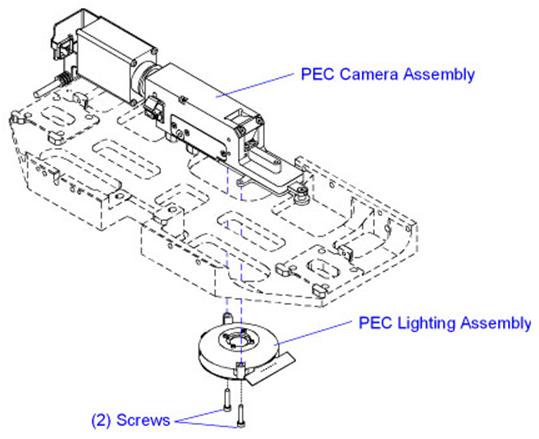
(New-style PEC mount shown below)

- Disconnect the PEC lighting cable from the PEC lighting. Set aside the PEC lighting.
- Remove the screws that secure the PEC camera to the carriage plate or mounting block.
- Carefully remove the PEC from the head cage.
- If installing a camera with a different magnification, remove the 6 frame fiducial inserts on the feeder uprights and the 4 nozzle changer fiducials on the nozzle changer. Retain for use with the .4 MPP PEC camera.
For UPS+ 7.5SC and higher with a .4 MPP PEC camera: Remove the 6 frame fiducial inserts on the feeder uprights; they will not be re-installed.
Install the PEC Camera Assembly
To install the PEC Camera Assembly, perform the following procedure:
- Carefully move the PEC camera into the head cage and position on the alignment pins.
- Apply Loctite 222 to the PEC camera mounting screws.
- Install the PEC camera mounting screws and torque to 1,36 Nm (12.0 in-lb.).
- Connect the PEC lighting cable to the PEC lighting.
- Install the PEC lighting to the new PEC camera and secure with the screws removed earlier.
- Route the PEC cables through the cable clamps on the bottom of the head cage.
- Connect the camera control/interface cables to the Head Cage Interface PCA.
- Install new cable ties to secure the PEC cables to the head cage. Do not over-tighten the cable ties.
- If installing a .4 MPP PEC camera where one did not exist previously, install the 6 frame fiducial inserts on the feeder uprights and the 4 nozzle changer fiducials on the nozzle changer. Install over the existing fiducials.
For UPS+ 7.5SC and higher with a .4 MPP PEC camera: Do not install the 6 frame fiducial inserts on the feeder uprights.
- Close the access cover.
- Power up the machine.
-
Determine if the machine is equipped with the Cognex Vision system:
- Open Diagnostics II.
- Select Version Information > Hardware Options > Vision Systems.
- Open Diagnostics II.
|
If Cognex Vision is… |
Then… |
| On the machine | Continue with the next step. |
| Not on the machine | Do the following:
|
- Calibrate the PEC camera and lighting. For instructions, see the PEC Calibration: Camera and Lighting (Multifunction Machines) help topic in Voyager.
PEC Camera Polarizing Components
The PEC camera consists of two elements: a rotating polarizer that covers four of the eight illumination petals and a sliding polarizer. The sliding polarizer is located in the camera aperture. The axis of this polarizer, frequently referred to as the “analyzer”, is orthogonal to that of the rotating polarizer. The combination of these polarizers on the module results in cross-polarized illumination.

(Typical PEC Camera shown)
The rotating polarizer ensures that the substrate is illuminated with linear polarized light. The metal features and ceramic background reflect polarized light differently. The light reflected from the metal has no net change in polarization. Because the orientation of the sliding polarizer located in the camera aperture is orthogonal to that of the rotating polarizer, most of the light reflected from metal features is blocked. Therefore, metal features appear dark on the camera.
In contrast, the ceramic surrounding the metal features randomizes the polarization upon reflection. Because the polarization is randomized, a portion of the reflected light can pass through the central polarizer and reach the camera. Therefore, the ceramic background appears as a shade of gray.
The following table summarizes the polarization effects on metals and ceramics:
|
Material |
Incident Polarization |
Reflected Polarization |
Central Polarizer Orientation |
Intensity at Camera |
|
Metal |
|
|
|
|
|
Ceramic |
|
|
|
|


Polarized Lighting Zones
The PEC Lighting Assembly has two lighting zones. Which zones are used for imaging depends on the type of substrate being imaged. The two lighting zones are shown in the table below.
|
Lighting Zone |
LED Color |
Graphic |
|
Zone I |
Blue |
|
|
Zone II |
Red |
|


Petal Zones I and II each contain four illumination petals positioned at 90 degrees to each other. The illustration below shows how the Red (R) and Blue (B) LEDs are oriented.
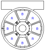
Selectable Polarizer Positions
The PEC Lighting Assembly is equipped with a rotating polarizing filter and high intensity LEDs. The PEC camera has a polarizing film mounted within a rotating ring and a second polarizer mounted on a slide above the lighting module. Certain classes of flexible circuits image well with cross-polarized illumination. For the polarized option, it is recommended that the central polarizer be left in place.
- The blue lighting zone of the PEC Lighting Assembly is designed to image flexible circuits.
- The red lighting zone of the PEC Lighting Assembly is designed to image ceramic circuits.
The following table summarizes the available Polarized lighting options:
|
Lighting Zone |
Graphic |
Function |
|
Zone I |
|
Orienting the rotating polarizer above the blue LEDs allows non-polarized illumination from the Red LEDs. This lighting type is effective on dark-colored ceramics. |
|
Zone II |
|
Orienting the rotating polarizer located above the red LEDs allows polarized illumination from the Red LEDs. This lighting type is effective on white or light-colored ceramics. |


