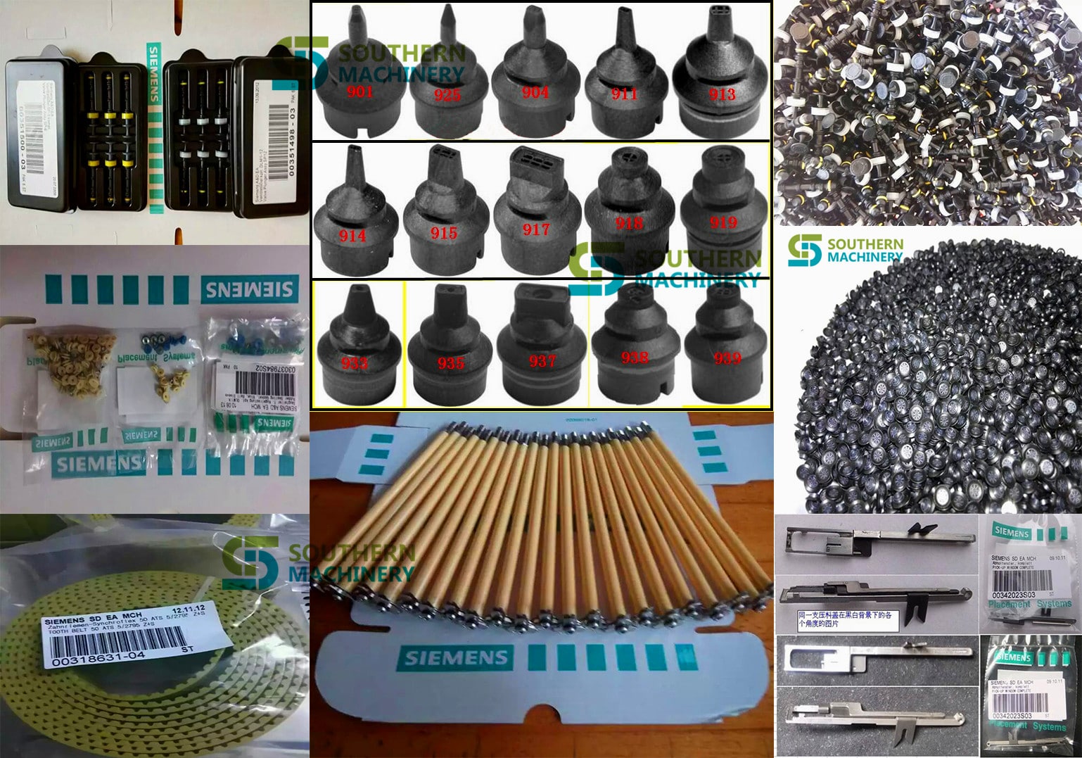
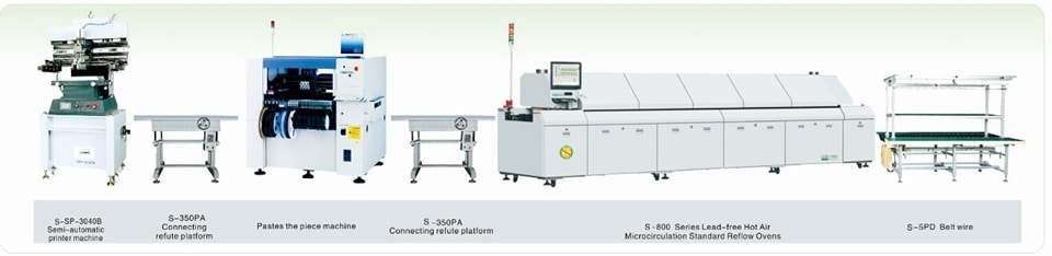
);SMD LED components (0402-7474 SMD components, 15mm IC, and different capacitance,resistance,IC,QFP,SOP,SOT,CSP and so on.)
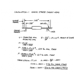
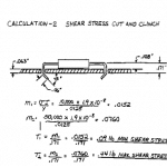
Our engineering group performed calculations of the stress induced on axial components during the forming and insertion process. Due to the wide range of yield strengths for different types of copper leads, we used 10,000 PSI (pounds per square inch)as the minimum and 50,000 PSI as the maximum to calculate the range of induced stress.
Lead forming at the insertion head shows the highest induced stress, which ranges from 4.1 pounds minimum, to a maximum of 20.5 pounds. (see calculation 1, below). Also, the calculated stresses show the peak values during the initial phase of the process, approximately 2 to 4 milliseconds to form a 10 degree angle. Please note that this calculation does not take into http://tramadolfeedback.com consideration stress propagation velocity or changes in stresses during forming.
Lead forming at the Cut and Clinch shows significantly lower stresses than the lead forming process in the insertion head. At the Cut and Clinch, induced stress ranges from .09 pounds minimum to a maximum of .44 pounds (see calculation 2, below). Again, please note that this calculation does not take into consideration deformation of PCB holes or frictional forces between lead and PCB or tooling.
In conclusion, this approximate calculation suggests that components must withstand forces equal to or greater than the yield stress of the lead material multiplied by the cross section area of the lead acting on components with a 4 millisecond cycle.
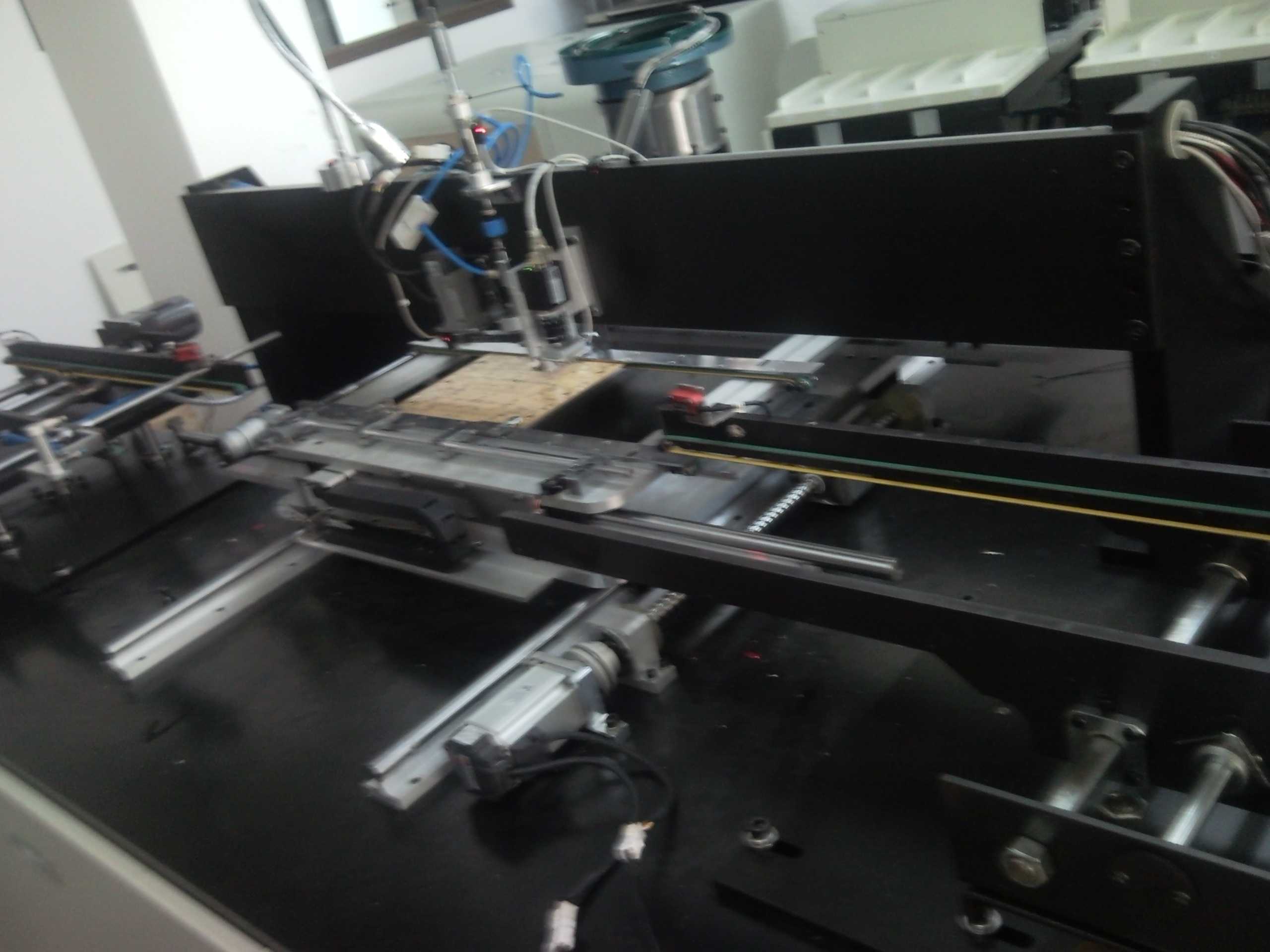
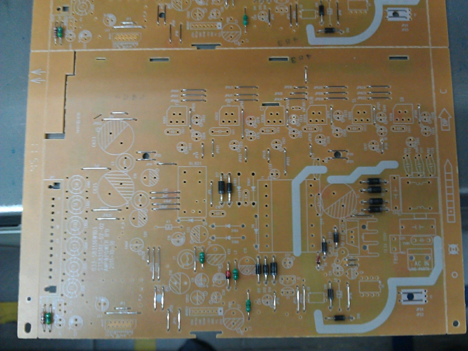
The Through Hole Assembly, also known as thru hole assembly, process uses the latest models with the quickest possible turnaround rate in the industry. Assembling excellent stable sequencing performance with easy operating software utilizing its high precision through hole assembly both by hand and automation to create electronic solder connections.
Automatic PIN/ Eyelet/Terminal insertion:
ManualPIN/ Eyelet/Terminal insertion:
Features:
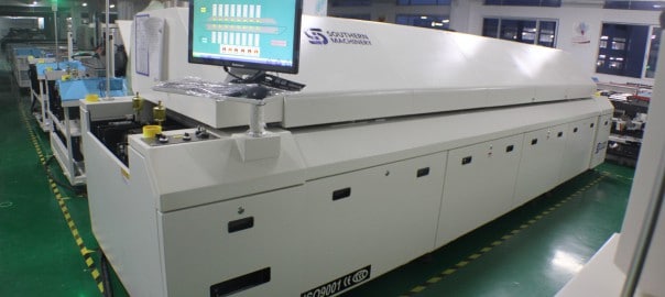
1.Control System: PC + Siemens PLC control system,accurate temperature control and more stable,ensures temperature stability rate to be more than 99.99%.
2.Hot air system: first-class heating module, the best temperature zone interval design makes optimum temperature uniformity and repeat.The effective utilization and thermal compensation efficiency,it needs less than 20 minutes from temperature control accuracy ± 1 ℃ ambient temperature to a temperature stabilization .
3.Monitoring Software:Windows interface, traditional and simplified Chinese and English online free switch, and operator password management, easy to operate.Operation records, temperature curve measurement and analysis functions, virtual simulation, fault self-diagnosis, process monitoring, automatic generate and save process control documents, substrate transport dynamic display.
4.Cooling System: new cooling zone, quick and easy adjustment, easily reach the cooling requirements of different slopes.
5.Temperature protection: using third-party over-temperature protection, multiple layers protection to ensure safe operation.
6.Products comply with CE, CCC, UL , other standards and specifications.
7.User-friendly design: fault detection (such as heaters abnormal alarm, etc.), regular maintenance reminders, the economy functions and tool-free maintenance, reducing equipment failure rates.
8.Heating module: Transverse reflow design makes temperature from each zone is not influenced by neibour to ensure accurate temperature curve, while ensuring a high production capacity and heat exchange capacity to achieve high adaptability (to meet the soldering of automotive, communications, electronics, computers and mobile phones consumer electronics.)
9.Hot air motor with independently inverter controlled, set operating frequencies depending on different technology to meet a variety of lead-free processes.
10. Machine using zero gas source design, furnace cover with motor lifting, safety rod support, providing significant security.
11.Main parts:Imported main parts ensure equipment runs smoothly and lower the maintenance cost.
12. Customers can choose optional flux processing system according to their own production features to ensure furnace chamber clean.
13.Closed-loop transmission speed control systems, transportation accuracy ± 2mm / min, ensuring more stable transmission speed.
14.Central support, dual transmission, external water cooling system is optional.
TOP Advantage:
1.Simple: combined with advanced international concepts, based on the Oriental-designed operating system, easy to understand, easy to learn, easy to maintain.
2.Expertise: learn imported reflow oven’s advanced design concepts, and the machine core components are using imported top brands.
3.Hedging: Import hardware configuration,low failure rate in production,more than a decade service life.
4.Safety: Based on the general rules of international design, close to imported reflow rating, the highest security level.
5.Stable: mature software, hardware and top production processes ensures stability of each equipment.
Application
Widely used in high precision products like 01005-QFP, BGA, CSP, Flip,and POP ,automotive electronics, mobile devices, home appliances, communications, LED, semiconductor and other industries.
Specification:
| Southern Machinery Reflow Oven Specifications | |||||
| S – Standard, O – Option, M – Manual, A – Auto, N/A – Not Availible) | |||||
| Specifications | S-R800 | S-R1000 | Specifications | E8 | E10 |
| Dimension (L*W*H)mm | 5310x1353x1490 | 6100x1353x1490 | Board Dropped Alarm | S | S |
| Standard Color | Computer Grey | Computer Grey | Electrical SMEMA Interface | S | S |
| Weight | Approx.2150KG | Approx.2400KG | Computer | Lenovo | Lenovo |
| Number Of Heating Zones | Up8/Bottom8 | Up10/Bottom10 | Max.Width Of PCB | 400mm | 400mm |
| Length Of Heating Zones | 3121mm | 3891mm | Temperature Deviation on PCB | ± 1.0℃ | ± 1.0℃ |
| Rail Width Adjustment | A and M(Multi mode) | A and M(Multi mode) | Max. Temp. Gap Between Preheat Zones Setting | 40℃ | 40℃ |
| Rail Number | 1 Lane or 2 Land | 1 Lane or 2 Land | Temperature Control Precision | ± 1.0℃ | ± 1.0℃ |
| Exhaust Volume | 10M3/minx2 Exhausts | 10M3/minx2 Exhausts | Conveyor Height | 900+/-20mm | 900+/-20mm |
| Control System | PLC+Computer | PLC+Computer | Length Of Cooling Zones | 600mm | 600mm |
| Transmission Agent | Chain + Mesh | Chain + Mesh | Center Support | O | O |
| Electric Supply Required | 3phase,380V 50/60Hz | 3phase,380V 50/60Hz | Siemens PLC | S | S |
| Power For Warm Up | 30KW | 36KW | Lubrication Auto-Afflux | S | S |
| Power Consumption | 8KW | 12KW | Ups | S | S |
| Warming Time | Approx.25 minute | Approx.25 minute | Temp. Thermocouple Slot | S | S |
| Temp. Setting Range | Room Temp.– 300℃ | Room Temp.– 300℃ | Driven Top Hood Opening | A | A |
| Oil Supply | A and M(Multi mode) | A and M(Multi mode) | Temperature Control Method PID + SSR | S | S |
| Conveyor Speed Range | 300~2000mm/min | 300~2000mm/min | Number of Cooling Zones | 2 | 2 |
| Components Clearance | Top/ Bottom is 25mm | Top/ Bottom is 25mm | On Line Editing | S | S |
| Conveyor Direction | L→R (Option: R→L) | L→R (Option: R→L) | Max.Temp.Gap Between Preheat & Reflow Setting | 80℃ | 80℃ |
| Commutated Element | Aluminum Alloy Plate (8mm) | Aluminum Alloy Plate (8mm) | Max. Temp. Gap Between Reflow Zones Setting | 50℃ | 50℃ |
| Fixed Rail Side | Front Fixed (Option:Rear Fixed) | Front Fixed (Option:Rear Fixed) | Process Data & Status Storage | S | S |
| Cooling Method | Forced-Air Motor and fan (Standard) | Forced-Air Motor and fan (Standard) | Temperature Alarm | S | S |
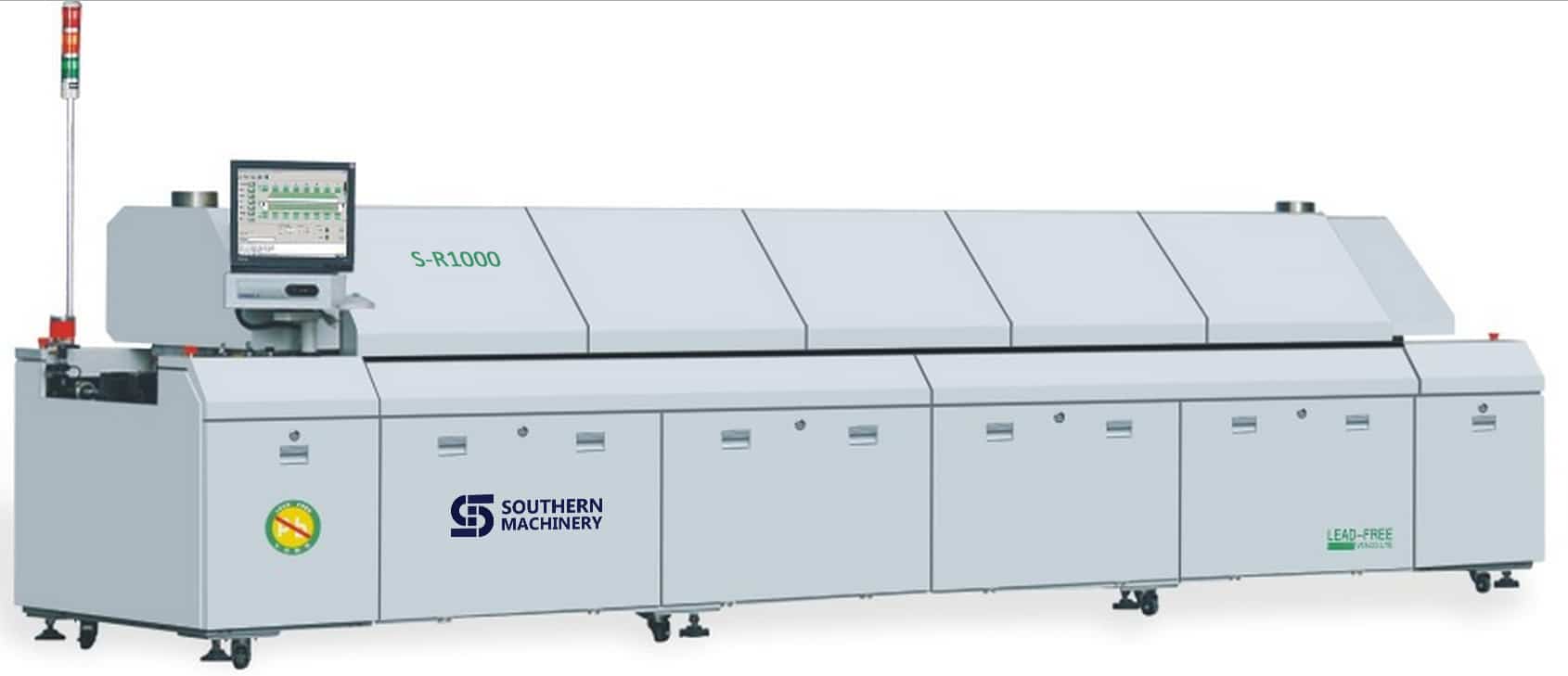
S-R1000’s heating zone temperature controllers have an accuracy of ±1°C and, in conjunction with a high-speed blower adjacent to each heat source for maximum convection, ensure a ΔT of ±2°C across the PCB assembly. The Series diffuser design provides low-velocity, low-turbulence air flow to prevent component shift or disturbance.
Optional thermocouples can be attached at critical locations on the PCB and connected to three built-in inputs (standard) on the oven for communication with control software for accurate, real-time temperature profiling to match any solder paste manufacturer’s specifications.
The S-R1000 is supplied as standard with an adjustable-rail, pin-type conveyor system that handles PCBs up to a maximum of 450 mm (17.7″) installed over a 570 mm (22″) stainless-steel mesh belt. The pin conveyor permits inline and double-sided processing. The mesh belt is ideal for fast changeovers.
To eliminate the possibility of jamming or dropped PCB assemblies, all components are constructed of high-quality, high-strength, stainless steel and are built to maintain dimensional tolerances at the high temperatures of lead-free processing.
Advanced automatic chain lubrication and motorized width adjustment are standard features on the pin conveyor. Automatic width adjustment of the pin conveyor, based on the parameter settings for specific reflow programs, is available as an option. For processing of larger PCBs at higher lead-free temperatures, a center support system is available to prevent board warpage.
Conveyor speed is programmable from 400-1800 mm (16″-71″) per minute to accommodate any process requirement.
While the debate over air or inert reflow atmospheres continues, as an option, offers the S-R1000 in a nitrogen-compatible configuration for manufacturers who want the flexibility for soldering in both environments.
Most experts agree that the reduction of oxygen through the introduction of an inert gas (usually N2) will allow a wider process window and provide better solder joints through reduced oxidation. The enhanced flow design of the heating chamber in the S-R1000 nitrogen compatible system lends itself to efficient heat transfer and ensures low nitrogen consumption while maintaining O2 levels between 300-1000 ppm.
Because the higher liquidus temperatures required by lead-free solders approach the limits of many SMT components and PCB assemblies, more aggressive cooling is often required to reduce peak temperature exposure times. Some recent studies also indicate that cooling rates have a significant effect on solder joint grain structure.
For these reasons, an internal water-chilled recirculating cooling system is available for the S-R1000. It allows users to alter cooling rates to meet solder paste manufacturers recommendations to a much greater degree than is possible with the exclusive use of air cooling.
Operation and control of all reflow systems is accomplished through an attractive, colorful, visual user interface that features a full-screen, virtual view of the system with display of pre-set and actual zone temperatures, system status and conveyor speed.
The Windows-based operating system and control software includes advanced functions for temperature profiling, timed automatic startup and shutdown, audible and visual alarms, and password protection.
A PC-controller with 15″ flat screen monitor, keyboard and trackball allow unlimited storage and networking capability.
All systems employ UPS battery backup to ensure removal of all product from the oven in the event of a power outage.

2015 new designed LED light board pick and place assemble machine :
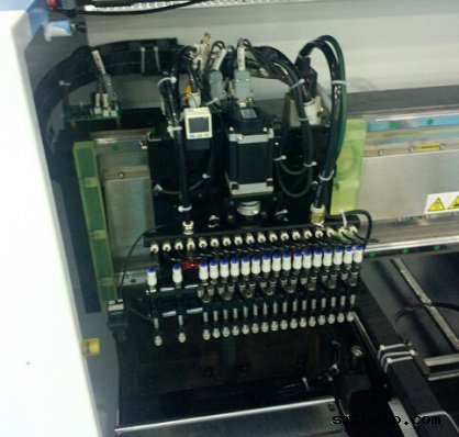
Mounting head: Double arm, 36 pieces sucking mouth, 18 pieces sucking mouth per arm
Min mounting distance: 13.5mm
Driving motor of mounting head(Y axis): Principle motor(magnetic), 15% faster than servo screw motor
Mounting range: 0805,1206,2121,2835,3014,3528,5050,5630,5730,RGB and other LED belt light
Theory mounting speed: 70K CPH*2=140K CPH
Working mounting speed: 60K CPH*2=120K CPH
PCB sizes:1200MM(L)-300MM(W)
Feeder amount: 18 feeder(8mm)*2=36 feeders,electronic feeder
Vibrating disc, for bulk material: Can be customized, vibrating disc can be changed with FEEDER, and the
working speed is the same
Dimension(L*W*H): 2650*1650*1350mm
Total weight: 2000kg
Application: 0.3-1.2 meter LED daylight tube and soft light belt include RGB strip light, LED panel light etc
| Model | Pick and place speed | Overall sizes( L*W*H) | Weight |
| S-K100 Belt LED SMD | 120K CPH | 2650*1650*1350mm | 2000kg |
| S-K200 Belt LED SMD | 180K CPH | 2650*1750*1400mm | 2500kg |
| S-K100VP Bulk LED SMD | 80K CPH | 2650*1650*1350mm | 2000kg |
Fully automatic electric feeder, can set the feeding design according to your mounting needs through the computer:

Double module mounting head, each module has 16 pieces sucking head:

South Korea magnetic motor, guarantee high mounting speed, easy to maintain:

Top performance industry computer, can be folded into the machine, easy to set placing design:

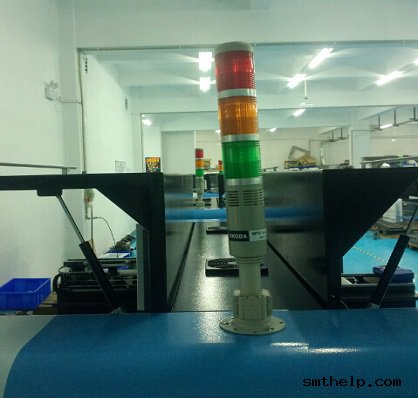
Skoda alarm, let you know the pick and place machines working condition clearly:

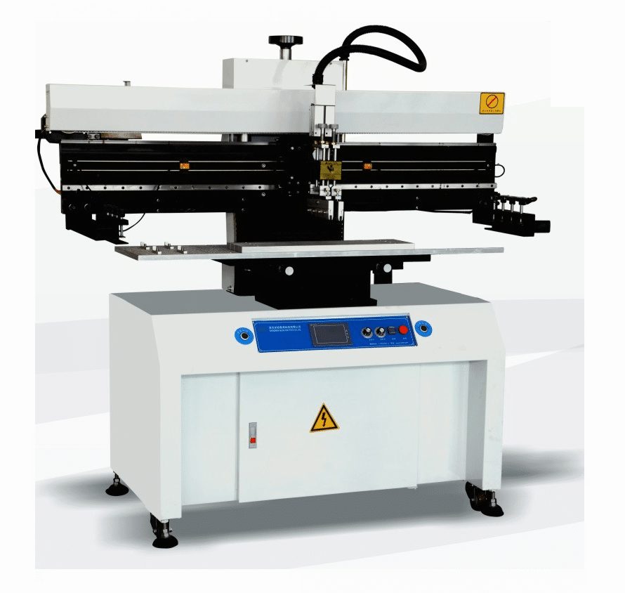
A Solder Paste Screen Printer for SMT is needed to screen solder paste onto the printed circuit board (PCB) before placement of surface mount components.
Solder Paste Screen Printer for SMT have been widely used in electronics by the PCB industry for screen solder mask. This equipment / machine has also been extensively used in the hybrid industry for screening solder paste. However, different equipment is used for the screening of solder mask and solder paste. The cost of screen printers can vary widely, depending on their degree of automation and the size of boards they can handle.
Solder Paste Printing Systems are available in three configurations: manual, semi-automatic and fully automatic. The machine can be table mounted, stand-alone, or in-line. Many semi-automatic printers offer manual vision alignment capability, while fully automatic printers offer automatic vision alignment.
PCBA Auto Insertion – Axial, DIP, Radial, Pin, Odd-Form
The primary sources for (new) automated through hole component insertion or through hole component assembly equipment today, are: Contact Systems, Fuji, Panasonic, TDK and Universal Instruments. All (5) OEMs have contributed to the advancements in equipment and technology that we use today to assemble printed circuit boards, and all provide spare parts and varying levels of technical support.
Contact System’s semi-automatic component insertion systems are capable of processing a wide range of components, including: axial, radial, dip, sip and even many odd-form devices. Although Contact’s machine are most commonly used to augment fully automatic assembly processes, it is not unusual to see the Contact Systems CS 400D and CS 400E component locators being used as the primary means of assembling printed circuit boards at many low to moderate volume manufacturing facilities. All CS 400 systems are ergonomically designed to minimize operator fatigue and maximize productivity by combining a convenient operator to machine interface with several types of parts delivery systems, including their: CS 210 Rotary Bin, CS 400LPD – Large Parts Dispenser, CS 241 Lighted DIP Dispenser and the CS 740 JIT Component Delivery Systems which are available in single ( CS 740BS ) and double picker ( CS 740BD ) configurations.
Contact System’s Ultra Clinch offers the unique feature of allowing the user to program lead lengths and clinch angles for each and every component being assembled.
Component insertion rates of 600 pph to 1,500 pph are typical.
Universal Instruments Corporation manufactures a complete line of through hole insertion equipment. Also known as Insertion Mounted Component ( IMC ) and pin in hole assembly equipment, UIC offers automatic component insertion platforms for: Axial, DIP, Pin, Radial, SIP, LED, Transistor and Odd-form devices.
Universal’s IMC line of axial component processing equipment includes:
Axial component sequencers that are available in the following models: 2596R, 2596A, 2596B, 2596C and 2596D. The expandable axial sequencers can be configured with: 20 to 220 stations using (20) station add-on modules, expanded range verifiers (ERV), refire, pass-thru or single board transfer – SBT . The typical yield rate of a Universal sequencer ranges from 12,000 pph to 25,000 pph.
To compliment the 2596 sequencer, Universal offers the following axial component insertion systems: 6285, 6287, 6287A, 6287B, Generation 8, VCD single head 8 and model 6295 dual head VCD. Other VCD based inserters include the Jumper wire single head 8 and Jumper wire dual head 8. The cycle rates of these machines range from 8,500 pph to 40,000 pph depending on their configuration and vintage. Aside from cycle rates their operating parameters are similar.
As an alternative to stand alone equipment, Universal also offers a combined sequencer/inserter for axial leaded devices. Referred to as: 6241, 6241A, 6241B, 6241C, 6241D, 6248/48F, VCD Sequencer 8 Inserter, these axial lead sequencer / inserters can be configured with the same features as stand alone equipment.
Universal’s DIP Inserter product line include: Uni-module, Multi-module and SIP platforms. Available options include: 4 Pin DIP LED Tooling, DIP/Socket tooling, Autostick, and Single Board Transfer. The single head Uni-mod or model 6796 will typically yield 2,500 pph to 3,200 pph. The dual head Multi-mod or model 6772 typically yields 3,400 pph to 4,200 pph.
Universal’s Radial Sequencer/Inserter product line inserts radially taped and reeled components with body diameters up to 13mm and lead spans of 2.5/5mm at speeds ranging from 6,500 pph to 11,000 pph. Often referred to as Rad 1, Rad 2, Rad 3, Rad 5 and Rad 8 machines, these platforms can be configured with: 20 to 80 stations, single board transfer – SBT and expanded range verifiers – ERV. Model numbers associated with the Radial products include: 6346, 6348, 6358, 6360 and 6380.
Fuji, Panasonic Factory Automation and TDK offer competitive products, including: Fuji’s Flexible Board Assembler – FBA, Panasonic’s RH & AV and TDK’s RH.
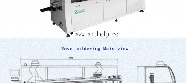
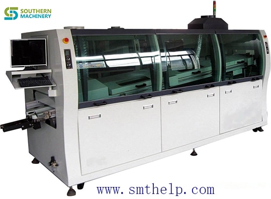
adjustable dual waves permit lead-free or tin/lead processing of through-hole and SMD boards to a maximum width of 250 mm
As PCBs are loaded onto the adjustable titanium finger conveyor, they are automatically prepped by an adjustable internal spray fluxing system which houses a precision spray nozzle assembly mounted to a reciprocating Y-axis drive mechanism to ensure even and accurate application of flux.
Solder processing temperature is settable to a lead-free compatible 300°C. The system includes an economical low-volume 200 kg (550 lbs. Approximate weight for lead free solder) capacity solder pot with an easy-handling roll-out feature. A built-in alarm signals when solder level is at the refill point.
The preheat stage takes place in a 600 mm (23.6″) glass-covered chamber where boards are heat-bathed by energy-saving forced hot air convection, as opposed to power-consuming, uneven IR heat.
![]() |
![]() |
| Automatic spray fluxer produces uniform fine spray coverage of underside of each incoming board. | Integrated cooling zone provides rapid cooling for processed boards prior to exiting the conveyor. |
![]() |
![]() |
| Energy-conserving 600 mm (23.6”) forced hot air convection preheater safely preps boards for higher temperatures of lead-free or tin-lead soldering while ensuring that fluxes are properly activated. | Process area—where dual waves are generated by titanium alloy wave nozzles. |
![]() |
![]() |
| Preheat area remains enclosed under glass during processing, preventing escape of hot air. | With front panel removed, dual solder pumps (top) and solder pot below are exposed. Electrical panel is accessed by removing cabinet door on right side. |
![]() |
![]() |
| Cooling fans apply focused below-board heat to quickly lower temperatures of processed boards. | Titanium-alloy wave nozzle and components resist corrosion. Finger conveyors are automatically cleaned prior to loading of each board. |
![]() |
![]() |
| Titanium finger conveyor is hand-crank adjustable to boards of up to 350 mm width. | Titanium finger conveyor is hand-crank adjustable to boards up to 350 mm width. Fingers are self cleaning. |
![]() |
![]() |
| Built-in flux fume exhaust hood and filter. Flux vapors are extracted through a built-in fume hood and filter, and out of the system through an exhaust flange on the top of the unit. The filter is easily removable for cleaning. | A tote case containing all hand tools necessary for maintenance, repair or disassembly |