Do you want make the Satellite receiver?
We provide total solutions for PCB assembly, stop to import electronic product from China.

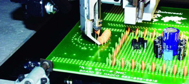
We provide total solutions for PCB assembly, stop to import electronic product from China.
WHAT’S IMPORTANT TO YOU
When selecting an SMT screen/stencil-cleaning process, it is critical to prioritize the deciding factors that are
most important to the user.
• Can the process effectively clean fine and ultra fine-pitch apertures?
• What flux do I need to clean now and will it be necessary to clean a different flux in the future?
• Can the process support these potential changes?
• Can the process clean dry as well as fresh paste?
• Are there other objects to clean, such as misprints, pallets, adhesives, etc.?
• What is the environmental impact?
• What is the capital investment?
• What is the operating cost?
• Are there any health or safety hazards to consider?
• Does the process have any detrimental effects on the stencil?
• What is the maintenance and potential downtime?
• Are there any special handling or storage requirements for flammable or hazardous chemistries?
• Who will take responsibility for correcting the process if it fails to perform?
1, No need electronic power, no fire and detonate caused.
2, Simple operation, only Start, Stop and Reset, that is all….
Posted by Auto Insertion on 2015年6月1日
1.Power down the machine and perform Lockout/Tagout according to local procedures.
2.Remove the feeder from the machine.
3.Loosen the mounting block locking set screw. Turn the set screw in until it just bottoms out, but do not tighten.
4.Use a flat blade screwdriver to turn the mounting block to be parallel with the housing as shown.
5.Tighten the locking set screw. Verify that the mounting block remains parallel to the housing. If needed, repeat adjustment until correct.
6.Loosen the eccentric locking set screw. Turn the set screw in until it just bottoms out, but do not tighten.
7.Rotate the eccentric to increase the clearance between anti-back-up dog and the ratchet wheel.
8.Place a 0,05 mm (0.002 in.) feeler gauge or shim stock between the anti-back-up dog and the ratchet wheel.
9.Rotate the eccentric adjustment screw until the shim stock can not be easily removed from between the anti-back-up dog and the ratchet wheel.
10.Loosen the eccentric until there is a slight drag.
11.Tighten the set screw after the correct clearance has been set.
12.Connect the air to the feeder and cycle the feeder observing the function of the anti-back-up dog.
13.If the anti-back-up dog fails to drop into position on any tooth, repeat the procedure and adjust the anti-back-up dog to the tooth where it did not correctly drop into position.14.Install the feeder on the machine.
End of Procedure
This adjustment prevents excessive lateral movement or binding between the
driver and housing. This adjustment may be performed with the feeder either
on the machine or removed from the machine and placed on a work surface.
Prerequisites:
Feeder Preliminary Forward Stroke Adjustment
To adjust the driver clearance, perform the following procedure.
1.Power down the machine and perform Lockout/Tagout according to local procedures.
2.Remove the feeder cover.
3.Extend the forward stroke until the cutters are approximately flush as shown. Insert a .001 inch (0.02 mm) feeler gauge between the driver
and the feeder housing as illustrated.
4.Remove the set screw. Apply Loctite 222 to the set screw, and adjust the set screw until the gap between the driver and housing is .001 inch
(0,02mm), as shown in the illustration. Do not overtighten or the feeler gauge will be difficult to remove.
End of procedure
Adjustments and maintenance procedures required to ensure the machine
operates efficiently are presented in the following subsections of this
document. These are:
– Feeder
– Low Parts Warning
– Component Lead Conditioner
