PCB Loader/Unloader The latest introduction to 2017

PCB  loader/unloader

The latest introduction of PCB loader/unloader 2017

Characteristics of the equipment.

PCB Automatic UNloader PCB conveyor

1.Special aluminum alloy mechanism to better understand the operation status of magazines.

  1. Stable casting platform structure design, improve the stability of equipment 0.3. Panasonic PLC control, multi-function circuit and program design, performance stability, ensure the smooth and smooth production line.
  2. Humanized programming, 4 kinds of PITCH selection, can set the step distance of receiving/transmitting PCB.

  3. Standard SMEMA communication interface, which can communicate with other automation equipment.

  4. The material box shall be transported by the engineering plate.

  5. Adjustable push plate speed control.

  6. Three-point positioning type upper and lower pneumatic clamping, ensure the location of the material box is accurate.

  7. Push plate protection system to ensure that PCB board is not crushed, reducing process loss. This equipment adopts SMT circuit board production line operation

PCB size: (mm):   50 x50~330 x445
Working height (mm): 900 + 20 (STD)
groove Change time:   bout 6 seconds
The machine size :1650(L)845(W)1250(H)
Step selection:  10.20.30.40 mm
Power supply:  AC 110/220v plus or minus 10V, 50/60hz knife bank
Dimensions (L * W * H, MM) : 355 (L) * 320 (W) * 565 (H)
Air pressure and gas flow : 4-6bar / 10 litres/min
Weight (KG):140 kg

自动装载机 PCB loader
loader


This equipment is used SMT circuit board production line operating upper and lower plates

PCB SIZE:(mm):50×50~330×250
Working height (mm):900±20(std)
Tank replacement time: about 6 seconds
Machine dimensions:1920(L)845(W)1250(H)

Step Select: 10.20.30.40 mm
Power Supply: AC 110/220V±10V, 50/60HZ
Magazine size (LWH,MM):355(L)320(W)565(H)
Barometric pressure and gas flow rate: 4-6bar/up to 10 l / min
Weight (KG):260KG

PCB Automatic UNloader

PCB

SMT loader

SMT loader
This equipment is used SMT circuit board production line operating upper and lower plates
AI smt线
AI smt line           

If you want to get more product introductions, please contact us:
www.smthelp.net
ming@smthelp.net
jasonwu@smthelp.net


PCB assembly

Surface Mount Assembly Classifications for EMS

Surface Mount Assembly Classifications

Three general classes for the intended end use of electronic assemblies have been established. As applications and functionality increase there may be overlap of equipment between classes. The owner of the application has the responsibility to determine the class that applies. Although a single class may be referenced, specific requirements defined in other classes may apply as well. If a class is not stated for a criterion then the single criterion applies to all classes.

Class 1: Consumer Products: This class of product includes non-critical applications which shall be reliable and cost effective but for which extended life is not the primary objective. Examples include products manufactured for general consumer applications.

Class 2 – General Industrial. This class includes high performance commercial and industrial products in which extended life if required but for which uninterrupted service is not critical. Application and environmental considerations should be taken into account.

Class 3 – High Reliability. Equipment in this class includes those equipment which continued performance is critical, equipment whose downtime cannot be tolerated, or equipment used as a life support item. Unless otherwise specified, Class 3 shall be used for soldering requirements on military electronic equipment.

Printed circuit assemblies are manufactured in a variety of ways, exclusively using smt devices or smt mixed with through-hole components. Boards which have both SMC’s and through-hole components are called mixed technology boards. Surface

mount components are conventionally attached to the substrate using the reflow or the wave soldering process. Typically PCBs are assembled in one of the following ways and categorized as:

Type 1:

SMC’s only are placed on one or both sides of a printed circuit board. The components are attached via the Reflow soldering process.

Type 2:

A combination of both surface mount and insertion mounted components on a printed circuit board. Both SMC’s and IMC’s are assembled on the top side of the board while SMC’s only are attached to the bottom of the board. Top side smt components are Reflow soldered, while the through hole and bottom side smt components are Wave soldered.

Type 3:

IMC’s are assembled on the top side of the board while SMC’s only are attached to the bottom of the board. The components are soldered in place via the Wave solder process.

The fast growth of these applications and advanced packages has led to the development of high density boards. As the industry increases the use of these boards and packages in its products, two of the greatest challenges that it will face are; establishing effective printing guidelines and utilizing equipment that can reliably produce a wide variety of assemblies.

A company’s success or failure in the surface mount industry will weigh heavily on its ability to adapt to automated manufacturing practices through innovative product design and development. Manufacturers can effectively compete in the electronics marketplace today only by utilizing automated equipment throughout the entire SMC assembly process. This includes addressing changes in the SMC production process from initial board printing to final inspection. The companies that do not act positively on these factors and successfully adapt to changing trends in the electronics market will find their business being lost to competitors and foreign ventures.

Type 1 – Single Sided SMT
SMT Components (Primary Side only)

Print Solder Paste Place SMT Components

Reflow Solder

Clean(if required) In Circuit Test/Rework

Surface Mount Process 1-13

AI, Auto Insertion : Axial Inserter; Radial Inserter; JW (Jumper Wire) Inserter; Odd form Inserter; PIN inserter; Eyelet Inserter; Terminal Inserter IM, Insertion Mount,MI,Manual Insertion,DIP,  PCB Assembly,Chip Mounter, Pick and Place,  IC Mounter, High Speed Mounter, Wave soldering,LED lighting, LED Lamp, LED Display,  LED tube,UPS, Power Converter, Power Adepter, Mobile Charger, PCB board handling system,  Loader, Unloader, Conveyor,Shuttle,Chip Mounter, Pick and Place, IC Mounter, High Speed Mounter Induction Cooker, AC, Electric Cooker, Fan, TV, Settle Box


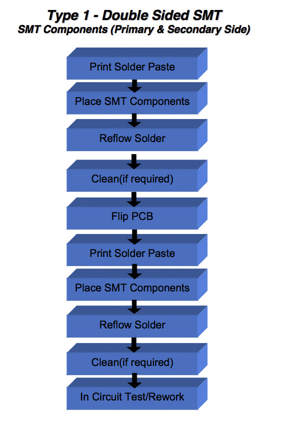
Type 1 – Double Sided SMT
SMT Components (Primary & Secondary Side)

Print Solder Paste Place SMT Components

Reflow Solder

Clean(if required) Flip PCB

Print Solder Paste Place SMT Components

Reflow Solder

Clean(if required) In Circuit Test/Rework

Surface Mount Process 1-14

AI, Auto Insertion : Axial Inserter; Radial Inserter; JW (Jumper Wire) Inserter; Odd form Inserter; PIN inserter; Eyelet Inserter; Terminal Inserter IM, Insertion Mount,MI,Manual Insertion,DIP,  PCB Assembly,Chip Mounter, Pick and Place,  IC Mounter, High Speed Mounter, Wave soldering,LED lighting, LED Lamp, LED Display,  LED tube,UPS, Power Converter, Power Adepter, Mobile Charger, PCB board handling system,  Loader, Unloader, Conveyor,Shuttle,Chip Mounter, Pick and Place, IC Mounter, High Speed Mounter Induction Cooker, AC, Electric Cooker, Fan, TV, Settle Box


Type 2 – Mixed Technology
SMT &Through-Hole Components (Primary Side) Passive SMT Components (Secondary Side )

Surface Mount Process 1-15

Squeegee Aperture Paste

On Contact

Frame

Print Solder Paste Place SMT Components

Reflow Solder

Components

Flip PCB

Place SMT Components

Cure Adhesive Flip PCB Wave Solder Clean (If Needed) Test / Repair

Insert / Clinch Through-Hole

PCB

Apply Adhesive (secondary Side)

AI, Auto Insertion : Axial Inserter; Radial Inserter; JW (Jumper Wire) Inserter; Odd form Inserter; PIN inserter; Eyelet Inserter; Terminal Inserter IM, Insertion Mount,MI,Manual Insertion,DIP,  PCB Assembly,Chip Mounter, Pick and Place,  IC Mounter, High Speed Mounter, Wave soldering,LED lighting, LED Lamp, LED Display,  LED tube,UPS, Power Converter, Power Adepter, Mobile Charger, PCB board handling system,  Loader, Unloader, Conveyor,Shuttle,Chip Mounter, Pick and Place, IC Mounter, High Speed Mounter Induction Cooker, AC, Electric Cooker, Fan, TV, Settle Box


Type 3 – Mixed Technology Through-Hole Components (Primary Side) Passive Surface Mount Components (Secondary Side )

Flip PCB

Place Surface Mount Components

Surface Mount Process 1-16

Insert / Clinch Through-Hole Components (Primary Side)

Apply Adhesive (Secondary Side)

Cure Adhesive Flip PCB Wave Solder Clean (If Needed) Test / Repair

AI, Auto Insertion : Axial Inserter; Radial Inserter; JW (Jumper Wire) Inserter; Odd form Inserter; PIN inserter; Eyelet Inserter; Terminal Inserter IM, Insertion Mount,MI,Manual Insertion,DIP,  PCB Assembly,Chip Mounter, Pick and Place,  IC Mounter, High Speed Mounter, Wave soldering,LED lighting, LED Lamp, LED Display,  LED tube,UPS, Power Converter, Power Adepter, Mobile Charger, PCB board handling system,  Loader, Unloader, Conveyor,Shuttle,Chip Mounter, Pick and Place, IC Mounter, High Speed Mounter Induction Cooker, AC, Electric Cooker, Fan, TV, Settle Box

How to improve Auto insertion machine spare parts lifetime ?

Continuity Tube Life Expectancy

Applies to tubes used in Generation 8 clinch units.

The expected life span of a Continuity Tube is dependent upon a number of factors including:

  • Lead Composition

A Continuity Tube that is subjected to steel leaded components will cause more stress between the cutter, the cutter Bushing, and the continuity Tube. Expect to experience a higher wear rate on a continuity tube that is subjected to stiffer lead material than a continuity tube that is subjected to softer leaded material.

  • Lead Diameter

A larger lead diameter will cause more stress between the cutter, the cutter bushing, and the continuity tube. Larger leads being cut will accelerate the wear of a Continuity Tube.

  • Tooling Maintenance

Worn Tooling (cutters and cutter bushings) will cause the scrap lead to ‘tear’ instead of cut with a sharp clean cut. This ‘tear’ in the lead will accelerate continuity tube on both the metal tube and the plastic surrounding the metal tube. The tooling should be changed at recommended intervals, sooner if tearing of leads is noticed.

  • Working Environment (dust, humidity, temperature, etc.)

The continuity tube should be kept as clean as possible. Dust buildup caused as a result of the cut/form process and clinching process will grind into the metal tube and the plastic surrounding the metal tube possibly causing accelerated wear of the continuity tube.

There are too many variables associated with the performance of a continuity tube to allow Universal to list it as ‘consumable tooling’ and publish an estimated life span. The greatest life span will be generated by keeping the continuity tube as clean as possible, keeping the lead length within the middle of acceptable lead length range, and changing the cutters and cutter bushings on a regular basis.

Continuity Tubes and False Insertion Errors

Proper continuity lead sense is dependent upon the relationship between:

  • the continuity tube
  • the cutter
  • the angle of the lead being cut
  • the lead length as the leads are cut.

It is important the lead is bent and touches the continuity tube before the cut takes place, making the position where the lead enters the cut and clinch assembly very important.

As the cutter moves across to the cut position, the lead begins to bend in the direction of the continuity tube.  However, once the lead is pinched between the cutter and the cutter bushing, the scrap portion of the lead will no longer be pushed toward the continuity tube.  At this point the scrap portion of the lead will actually be forced in the opposite direction of the continuity tube as the cutter shears through the lead.

The following scenario describes what happens if the lead length is set too short.  In other words, the lead entrance to the cutter bushing set so the lead is very close the cutter bushing shear point.

By setting the lead length too short, (the lead too close to the cut point of the cutter bushing), the scrap portion of the lead will not be bent far enough to reach the continuity tube as the cutter bends the lead, resulting in a false insertion error.  In other words, if the lead reaches the cut point before it has been bent far enough to touch the continuity tube, a false continuity error may occur.

On the other hand, having the lead length too long may cause accelerated wear and damage to the continuity tubes.  Forcing the lead into the continuity tube with too much force will cause denting of the continuity tube and wear of the plastic insulation, resulting in premature failure and false continuity errors over time. 

Cutter Stroke Speed and false Continuity Errors

The length of time necessary to drive the Cutter from the home position, to the extended ‘cut’ position, can affect continuity sensing.  If the cutter speed is set too slow, the cutter air pressure is insufficient, or a mechanical assembly used in the operation of the cutter stroke binds, the cutter will not reach the component lead in the ‘window’ of time necessary for continuity to be sensed.  This will result in a false continuity error.  Examples of cutter stroke speed problems:

  • Pneumatic flow control for the cutters not properly set
  • Poor air flow from the valve to the cutter
  • Binding in the mechanical linkage from the cutter piston to the cutter
  • Lack of sufficient lubrication in the mechanical linkage from the cutter piston to the cutter
  • Incorrectly set cutter backstroke (the starting position for the cutter)
  • A torn O-ring on the cutter piston which causes a bind in the cylinder
  • Lack of sufficient lubrication on the O-ring for the cutter piston

END

Ensuring the Best Design for Final PCB Production Stage with Testing!

Ensuring the Best Design for Final PCB Production Stage with Testing! Ensuring the Best Design for Final PCB Production Stage with Testing!

Avoiding Design Mistakes with Testing

Improve EMS Productivity by Testing Early

http://www.smthelp.net/product/high-speed-in-line-circuit-board-test-machine/

PC Board errors are a drain to EMS productivity. Through analysis and testing PCBs in the pilot stages, a smoother and more educated production set-up can be achieved. By performing automatic impedance measurements and testing of components (chip resistors and capacitors) early on, you can ensure the best design for production.

We recommend applying the best design logics when creating your PCB layout and Test, Test, Test for maximum efficiency and output. According to Circuits Assembly’s December 2016 Magazine, here is the list of 5 Most Common PCB Design Mistakes: “1. The components do not suit the production technology 2. Thermal imbalance 3. Incompatibility between fabrication and assembly technology 4. Component placement at PCB edge 5. Placing fiducials on the PCB’s edge.”

Once you have planned your PC Board with best practices, Southern Machinery’s High-Speed In-line Circuit Board Test Machine will help with testing by incorporating a visual inspection function which allows mounting status checks on each component (e.g.: typo descriptions in alphanumeric characters, orientation, size) on the operator’s monitor will serve to best analyze testing up close. As well as automatically generating test data from mounting data and component list.  

http://image.slidesharecdn.com/highspeedin-linecircuitboardtestmachine-fai-161223080028/95/high-speed-in-line-circuit-board-test-machinefai-14-638.jpg?cb=1482480094

http://image.slidesharecdn.com/highspeedin-linecircuitboardtestmachine-fai-161223080028/95/high-speed-in-line-circuit-board-test-machinefai-3-1024.jpg?cb=1482480094

http://www.smthelp.net/product/high-speed-in-line-circuit-board-test-machine/

AI/SMT spare parts

Profesional in AI/SMT machine and spare parts of AI/SMT .
1.We have original drawing ,what we can make is almost  the same quality with original spare parts.
2.All the process when manufactured ,our engineer would give guide and test the quality.
3.Only when the qulity is passed will we let the parts into our store.
4.Also we can control our spare parts in a very low price, when control it on a good quality.

AI accessaries4UEDF(J45NAM7Z9K`_OX{N6

How does SMT electronics assembly work?

Electronics manufacturing using surface-mount technology (SMT) simply means that electronic components are assembled with automated machines that place components on the surface of a board (printed circuit board, PCB).

SMT车间

Electronics manufacturing using surface-mount technology (SMT) simply means that electronic components are assembled with automated machines that place components on the surface of a board (printed circuit board, PCB). In contrast to conventional through-hole technology (THT) processes, SMT components are placed directly on the surface of a PCB instead of being soldered to a wire lead. When it comes to electronic assembly, SMT is the most frequently used process in the industry.

Electronic assembly encompasses not only placing and soldering components to the PCB, but also the following production steps:

  • Applying soldering paste, which is made of tin particles and flux, to the PCB
  • Placing SMT components to the soldering paste on the PCB
  • Soldering the boards with a reflow process.

Applying Soldering Paste

Applying soldering paste is one of the first steps in the SMT assembly process. Soldering paste is “printed” on the boards using the silk-screen method. Depending on the design of the board, different stainless-steel stencils for “printing” the paste onto the board and various product-specific pastes are used. Using a laser cut stainless-steel stencil custom made for the project, the soldering paste to be applied only to the areas where components will be soldered. After the soldering paste is on the boards, a 2D-soldering paste inspection is performed to ensure that the paste is evenly and correctly applied. Once the accuracy of the soldering paste application has been confirmed, the boards are transferred to the SMT assembly line, where the components will be soldered.

AI spare parts、Universal Parts,UIC,TDK.VCD Sequencer.SMT,THT,PCB,PCBA,AI,wave soldering,reflow oven,nozzle,feeder,wave soldering,PCB Assembly, LED, LED lamp, LED display AI spare parts、Universal Parts,UIC,TDK.VCD Sequencer.SMT,THT,PCB,PCBA,AI,wave soldering,reflow oven,nozzle,feeder,wave soldering,PCB Assembly, LED, LED lamp, LED display

Component  Placement and Assembly

The electronic components to be assembled come in trays or reels, which are then loaded into the SMT machine. During the loading process, intelligent software systems ensure that components are not inadvertently switched or misloaded. The SMT assembly machine then automatically removes each component with a vacuum pipette from its tray or reel and places it on its correct position on the board using precise pre-programmed X-Y coordinates. Our machines are capable of assembling up to 25,000 components per hour. After the SMT assembly is completed, the boards are moved on to the Reflow ovens for soldering, which affixes the components to the board.

S-320 pick&place machine

SMT line

Component Soldering

To solder electronic components, we use two different methods, each of which has distinct advantages depending on the order quantity. For series production orders, the Reflow-soldering process is used. During this process, boards are put in a nitrogen atmosphere and are gradually warmed up with heated air until the soldering paste melts and the flux vaporizes, which fuses the components to the PCB. After this stage, the boards are cooled off. As the tin in the soldering paste hardens, the components become permanently affixed to the board and the SMT assembly process is completed.

For prototypes or highly sensitive components, we have a specialized vapor-phase soldering process. In this process, boards are heated until the specific melting point (Galden) of the soldering paste is reached. This allows us to solder at lower temperatures or solder different SMT components at different temperatures depending on their individual soldering temperature profiles.

PastedGraphic-59

AOI and Visual Check

Soldering is the second-to-last step of the SMT assembly process. In order to ensure the quality of the assembled boards, or to catch and correct a mistake, AOI visual inspections are performed for almost all series production orders. Using several cameras, the AOI system automatically checks each board and compares the appearance of each board with the correct, pre-defined reference image. If there are any deviations, the operator of the machine is informed of the potential problem, who then corrects the mistake or pulls the board from the machine for further inspection. The AOI visual check ensures consistency and accuracy in the SMT assembly production process.

Dimensons_floor _layout - A_cmyk

Southern Machinery-AI and SMT machine/Accessaries/ELCINA member

Dedicated to provide customers with one-stop service, research and development, production, testing, sales, after-sales service, provide the whole line  sales and service .
According to the needs of customers, with our professional technology to provide customized service.
 
1.PCB AI/SMT Equipment Manufacture.Offering comprehensive solution in AI/SMT Technology
2.For different components process insert /Pick& Place , like Radial and Axial components ; odd form components (Rivet,Pin,Switch,Connector,Terminal and so on
);SMD LED components (0402-7474 SMD components, 15mm IC, and different capacitance,resistance,IC,QFP,SOP,SOT,CSP and so on.)
3.To meet the needs of different industries
(1)Electrical industries appliances:Air conditioner, Television, Microwave, Electric cooker, Electric kettle, Induction cooker etc.
(2)Power supply appliance: Vehicle power supply, Energy saving power supply, Ballast etc.
(3)LED application:LED lighting, LED display, LED lights, LED control systems, LED luminous characters.
(4)Vehicle industries application: Vehicle power supply, Vehicle light, Car audio etc.
(6)Energy saving lighting industries application: Industrial lighting, outdoor lighting, street lamp, floodlight etc.
(7)Other electronic industries application: Electronic watch, Electronic Instrument, electronic spare parts etc.
4.AI/SMT spare parts of different brand machine .
With the original drawing to provide high copy spare parts , To a large extent save much cost for customer ,and keep the spare parts life.
5.Have the most extensive contacts network, for customers to find all kinds of second-hand accessories.


PastedGraphic-10

Dispenser for high precision products

Fully automatic dispensing system bench top automatic visual glue dispenser  Automatic visual glue dispenser    is used to Chevrons,  fridge magnets, key chains,  power supply, cell phone,energy saving light, LED, DVD, DC, Switch, Connector, relay and other industries needing fluid glue solder.

Feature of  Glue dispensing equipment

1 Improve the production efficiency,reduce artifical loss.

2 Equipped with high performance CCD vision positioning system,visual dispensing route,improve accuracy.

3 Use industrial computer to control  operating system,

4 According to the different artifacts, choose suitable LED light source for lighting.

5 Adopt servo motor, ball screw drive.

6 It can arbitrary match with needle valve, diaphragm valve,screw valve, pnematic injection valve, piezoelectric injection valve.


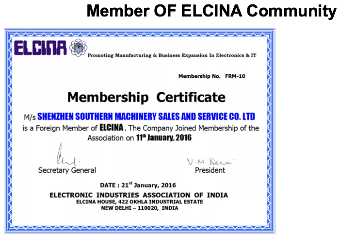
Congratulation SOUTHERN MACHINERY has beed admitted as Foreign Member of ELCINA community

http://www.elcina.com

Electronic Industries Association of India identifies and bringstogetherlikeminded companies to represent the voice of Indian electronics and IT hardware industry and promote manufacturing.Electronic Industries Association of India promotes hardware manufacturing through active representation in the Government as well as scientific/technical institutions and industry/trade organisations in India and abroad.Electronic Industries Association of India represents to the government, problems faced by its members, individually or as a group, to find solutions and provide relief from unreasonable acts of administrative and policy making departments.

Electronic Industries Association of India provides a bouquet of professional and value-added services to its members. These services are tailored to serve the best interest of its Members and the Electronics/IT community to empower it to face competition and prosper. These services are constantly upgraded to suit the changing demands of the environment and needs of the industry.

Electronic Industries Association of India’s E-commerce facilities and its dynamic website together attract about 3500 visitors per day and provide a platform for members.

Electronic Industries Association of India is a repository of information and research, readily available for its members and helps them in taking critical decisions based on relevant facts.

Services currently provided by Electronic Industries Association of India to its members can be found by clicking here.