High quality, original packaging, factory direct sales

Electronic component lead cutting by Manual
Automatic Electronic component lead cutting
.jpg)
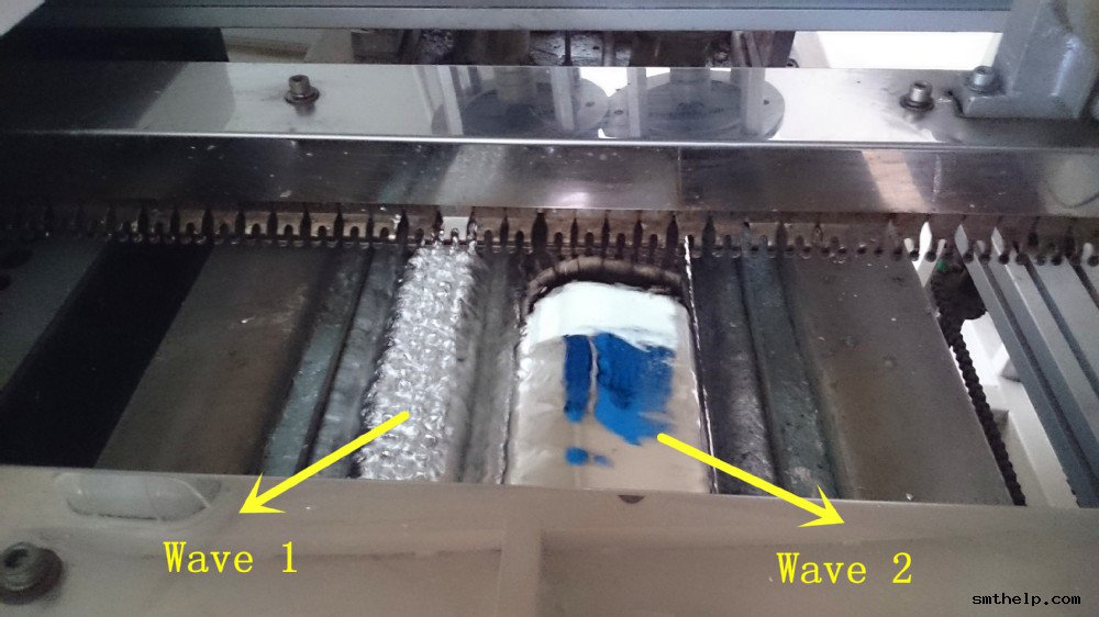
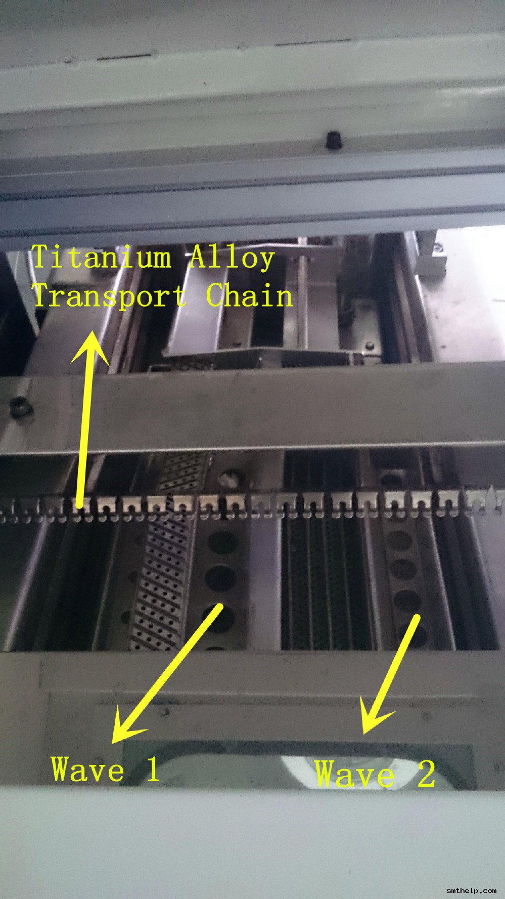
Southern machinery design and manufacturing wave solder machine, easy operation &maintenance, accurate temperature profile, flux saving,good soldering quality
—– 2. Non-tin-bonding to guarantee the quality of welding

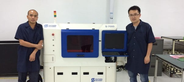
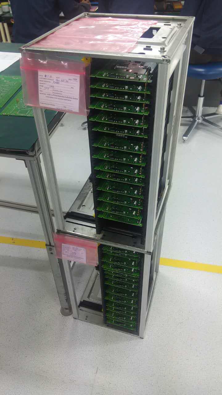
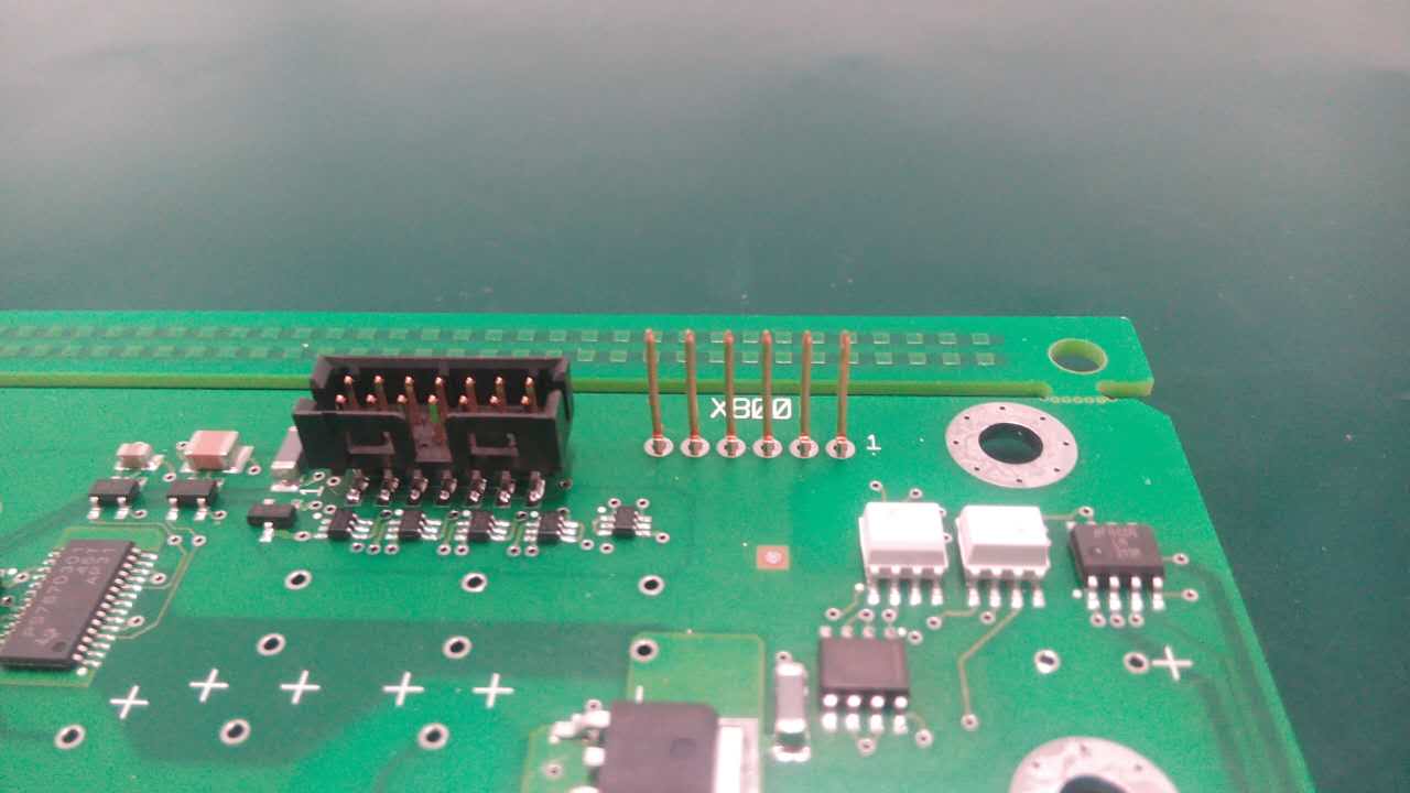
Southern Machinery just finish a new project in Thailand.
We sale a new model S-7000 to a thai customer in Samut prakan,maybe it’s the first TE square pin auto-insert machine in the world .
we send a engineer to thai for install this machine and training customer.
At last,we reach customer’s production target & quality requirements successfully



41059901 SLEEVE, BEARING 40821301 BUSHING 40520204 GO RINGS 40821201 BUSHING 40520201 GO RINGS


40520203 GO RINGS 40520202 GO RINGS 41499603 ANVIL, VSL 41499703 CUTTER FORMER 41499701 CUTTER FORMER
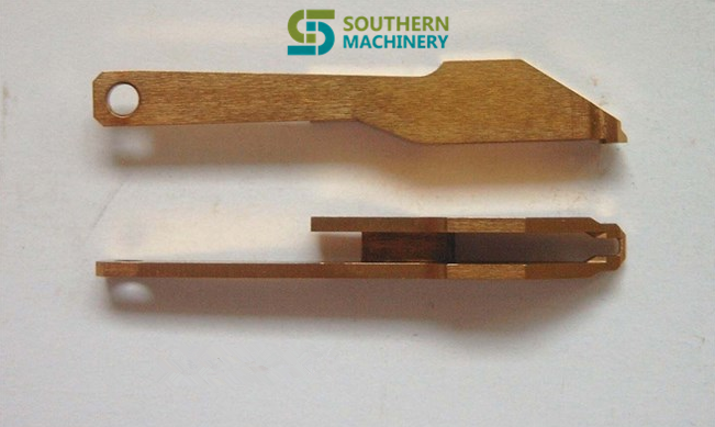

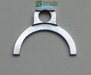
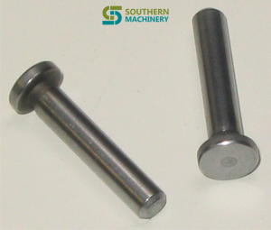
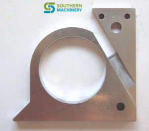
41499706 CUTTER FORMER 41700801 PIN & CLIP ASSY 41848601 CLAMP,RETAINER 41700803 RP 41700805 PIN 42480201 ESCAPE,RH


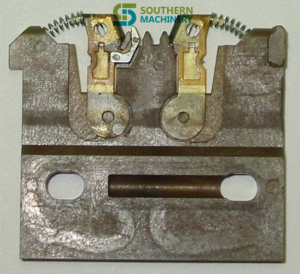


42480101 ESCAPE,LH 42804702 CARRIER CLIP ASSY 42804703 CARRIER CLIP ASSY 42718601 CLAMP 42740613 FITTING


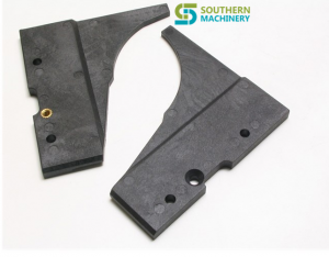

42717602 HOUSING 42686801X CARRIER CLIP II ASSY 42509001 ROLLER 42513301 RAMP 43366105 FORMER,LEFT
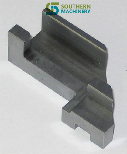
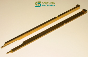


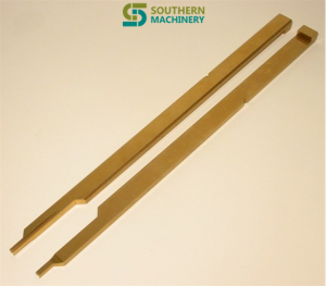
42502501 SLIDE SLIDE 43366205 FORMER,RIGHT 43366107 FORMER,LEFT STD 43461501 CUT FORM 43366207 FORMER

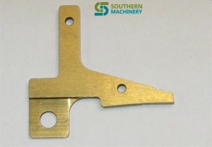

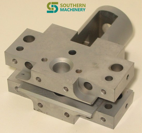
43461601 CUT FORM 43461801 ANVIL 43470602 HOUSING,CLINCH 43470601 HOUSING,CLINCH 44241906 ARM
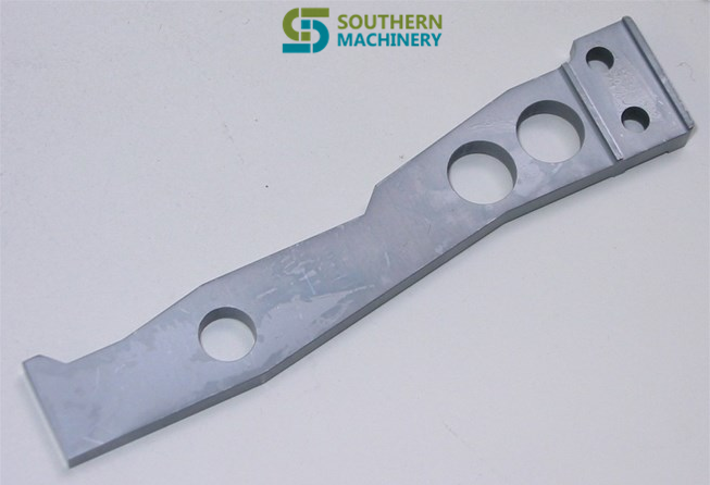
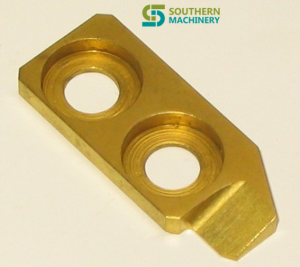
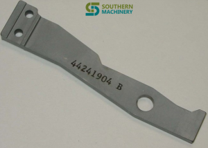

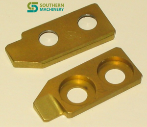
44241912 ARM KICKOUT-RH 44241505 FORMER 44241904 ARM KICKOUT STD RH 43871802 CUTTER 44241405 FORMER
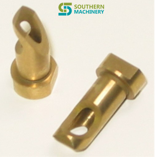


43871702 BUSHING 43871701 BUSHING 44242004 ARM,KICKOUT,STD,LH 43556202 CLAMP 44242012 ARM
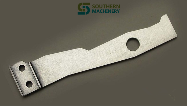


44242006 ARM 44266704 DRIVER TIP,R 44266703 DRIVER TIP,R 44281702 BUSHING CUTTER,STD 44266803 DRIVER TIP,L



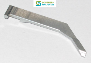
44426606 PUSHER, UPPER 5.0 44426701 PUSHER, LOWER 44896802 SUPPORT,GUIDE 44962901 SHAFT 44629802 CLAMP, JAW
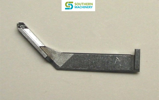

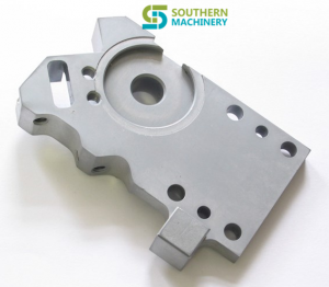

44629902 CLAMP,DUAL JAW 44629702 CLAMP, JAW 44629706 CLAMP 44624302 PLATE, TOP 44629502 GUIDE,DUAL JAW


44624203 STOP 44963001 BEARING 44963002 BEARING 44964701 PISTON, ANVIL 45095202 HOLDER, LATCH


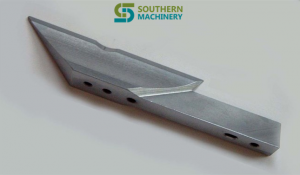
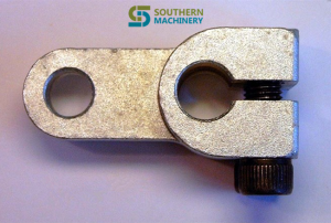

45053801 LATCH 45251701 ANVIL-STD 45218501 SPREADER 45345501 CLEVIS ACTUATOR ASM 45315502 PLUG

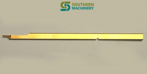


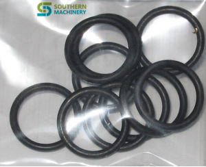
45592601 BLADE 45592520 FORMER 45592420 FORMER 45592508 FORMER 45586701 O-RING .489 X .070
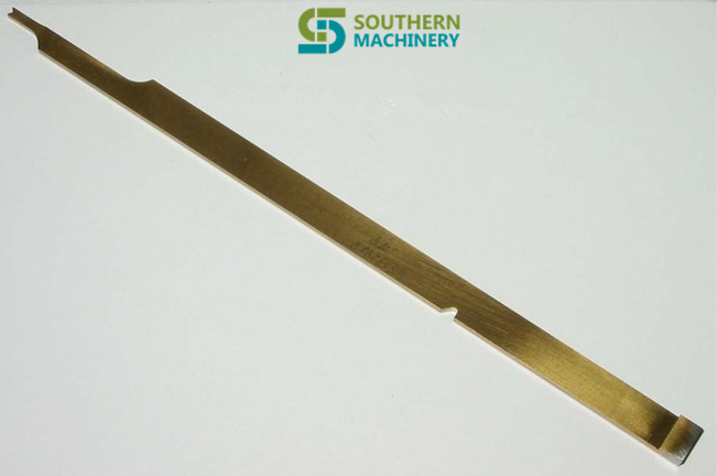


45592408 FORMER, 45452001 SPRING, EXTENSION 45575702 CUTTER,ANVIL 45592701 BLADE 45373901 SPRING


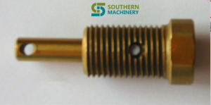
45744401 BUSHING,CUTTER 45798406 TUBE 46276401 RATCHET DRIVE DETENT 45988201 INDEX WHEEL 46488901 STOP,ACTUATOR

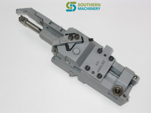
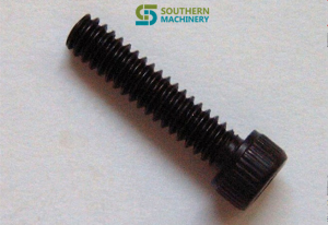
46287002 FLAG,MOLDED 47062501 RP 47062502 SPRING 46500701 INS HD ASSY 80000109 SHCS 4-40 X 1/8 80000104 SHCS 4-40 X 1/2

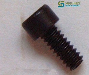
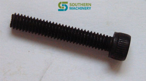
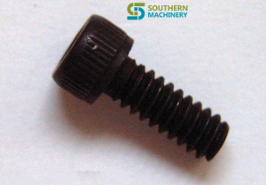

80000101 SHCS 4-40 X 3/16 80000102 SHCS 4-40 X 1/4 80000407 SHCS 8-32 X 1 80000302 SHCS 6-32 X 3/8 80003815 SSS 10-32×1/2

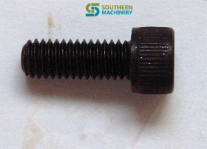

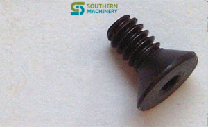
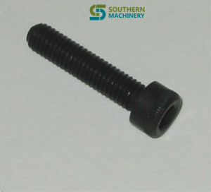
80002608 SFHS 10-32×3/8 80000515 SHCS 10-32 X 1/2 80000608 SHCS 1/4-20 X 1-1/4 80002201 SFHS 4-40×1/4 80000518 SHCS 10-32 X 7/8

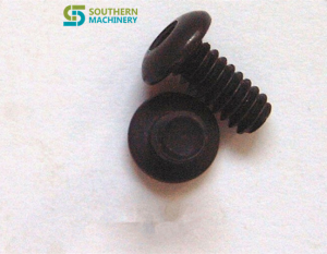
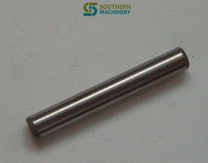


80000514 SHCS 10-32 X 3/8 80001301 SBHS 4-40×1/4 80009905 SDP 1/8 X 7/8 80010103 SDP 1/4 X 3/4 SDP 80004602 SSS 4-40×3/16

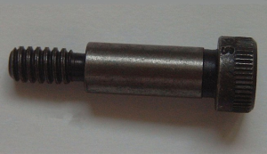
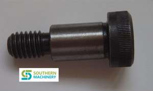

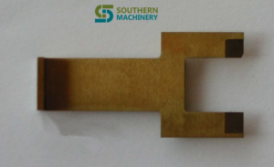
80007204 SSSOP 1/4-20 X 3/4 80011003 SHSS 1/4 X 5/8 80011303SCREW SHSS 1/2×3/4 80010106 SDP 1/4 X 1-1/4 90055225 PUSHER,PULL DOWN


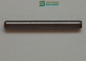
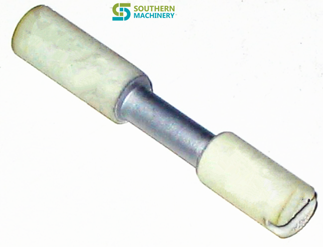
80011205 SHSS 3/8 X 1 80018705 SLW #10 90054811 HOUSING,CLIP 7.5.5.0 80025913 PIN 90050416 ECCENTRIC,INSULATED


HEXNUT-MS 10-32 O-RING .049 X .103 SDP 1/16 X 3/8 O-RING .125 X 070 PISTON & SHAFT UNIT
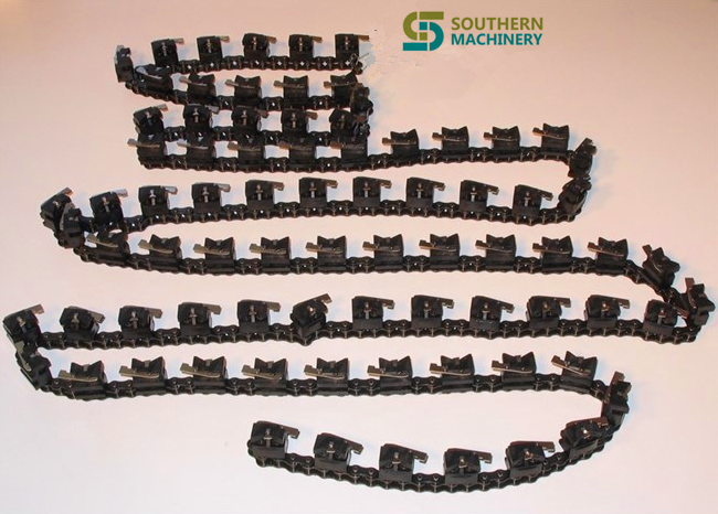

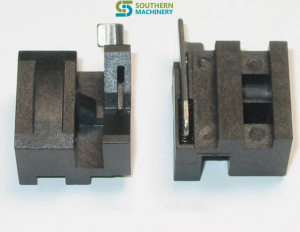
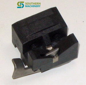
40152406 STD HD CHAIN ASSY 40152306 LEFT STD CLIP ASSY 40152302 OUTSIDE CLIP ASSY-LH 40152206 RIGHT STD CLIP ASSY

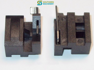
40152304 LEFT STD CLIP ASSY 40152301 OUTSIDE CLIP ASSY
Southern Machinery : To Provide professional solution of SMT/AI & SMT peripheral equipments. We provide totally…
由 Auto Insertion 发布于 2015年12月14日
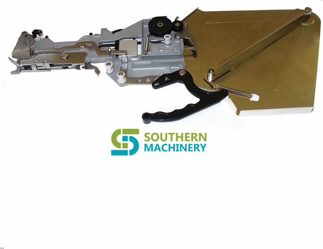
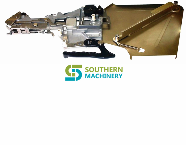
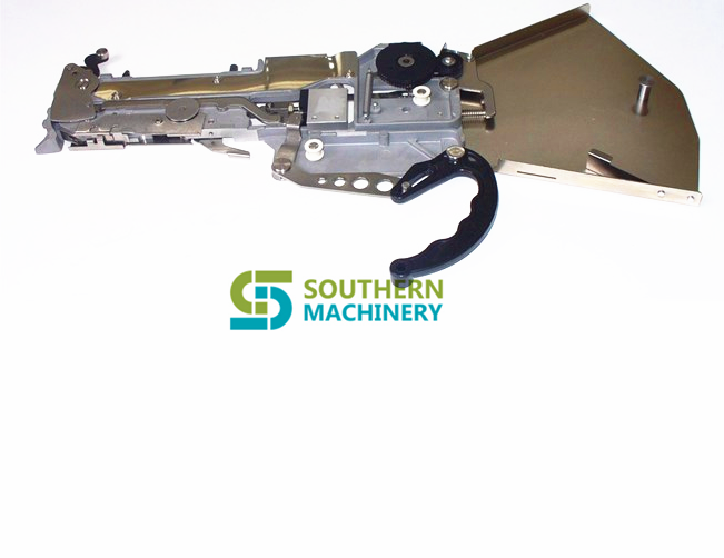
|
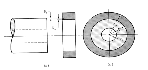
This calculates the delfection of the outer race of a bearing when it is pressed into a housing. |
|
|
|
|
|
These equations are from Shigley and Mischke “Mechanical Engineering Design” Fifth Ediion p.62-63 |
|
|
|
|
|
|
|
|
|
|
|
|
|
|
|
|
|
Bearing |
|
|
Housing |
|
|
Modulus of Elasticity of Inner component (Ei) |
30000000 |
|
Modulus of Elasticity of Outer component (Eo) |
10300000 |
|
Inner Radius of Inner Component (land radius)(ri) |
0.1705 |
|
Outer Radius of Outer Component (ro) |
0.3 |
|
Poisson’s Ratio of Inner Component (vi) |
0.292 |
|
Poission’s Ratio of Outer Component (vo) |
0.334 |
|
|
|
|
|
|
|
Radius at Press (interface) (R) |
0.1875 |
|
|
|
|
Radial Press (d) |
0.0003 |
|
|
|
|
|
|
|
|
|
|
Results |
|
|
|
|
|
Resulting Pressure (p) |
2599.55178212877 |
|
|
|
|
Increase in Housing Outer Radius (delta ro) |
0.000123796616002366 |
|
|
|
|
Decrease in Bearing Inner Radius of OD (delta ri) |
0.000176203383997634 |
|
|
|
|
|
|
|
|
|
|
|
|
|
|
|
|
|
|
|
|
|
|
|
|
|
|
|
|
|
|
|
|
|
|
|
|
|
|
|
|
|
|
|
|
|
|
|
|
|
|
|
|
|
|
|
|
|
|
|
|
|
|
|
|
|
|
|
|
|
|
|
|
|
|
|
|
|
|
|
|
|
|
|
|
|
|
|
|
|
|
|
|
|
|
|
|
|
|
|
|
|
|
|
|
|
|
|
|
|
|
|
|
Assumptions: |
|
|
|
|
|
Both members have the same length. |
|
|
|
|
|
Cross sections are uniform. |
|
|
|
|
|
Radial interference is constant around the circumference. |
|
|
|
|
UBUG Users Guide ( Debugger reference manual )
for Radysis Motion Controler
The
UBUG monitor is a stand alone software package designed to allow
evaluation and debugging of the UIMC 68EC030 based motion controller
PCB. It has the capability to load and execute user code and includes
an assembler/disassembler designed for quick program patchwork. The
monitor operates in a user interactive command driven mode signified by
the UIC> prompt. The command line entered after this prompt
determines which operation is performed.
UBUG MONITOR
TABLE OF CONTENTS
1. GENERAL INFORMATION
1.1 Description of UBUG………………….. 3
2. THE UBUG COMMAND SET
2.1 Introduction………………………… 3
2.2 Auto Null (an)……………………… 4
2.3 Assembler/Disassembler (as) ………….. 4
2.4 Block of Memory Fill (bf)…………….. 6
2.5 Block of Memory Move (bm)…………….. 6
2.6 Break Point (br)…………………….. 6
2.7 Block Search (bs)……………………. 7
2.8 Counter Test (ct)………………. 7
2.9 DAC16, ADC8 Test (dac16t)……………. 7
2.10 Data Conversion (dc)…………………. 8
2.11 Go (go)…………………………….. 8
2.12 Help (?/he/help)…………………….. 8
2.13 IO Access (io)……………….. 8
2.14 Load S-Records (lo)………………….. 9
2.15 Memory Display (md)………………….. 9
2.16 Memory Modify (mm)…………………… 10
2.17 Memory Test (mt)………………….. 10
2.18 Register Display (rd)………………… 10
2.19 Register Modify (rm)…………………. 11
2.20 Symbol Define (sd)…………………… 11
2.21 Test – Diagnostic (test)………………. 11
2.22 Transparent Mode ™………………… 12
2.23 Trace (tr)………………………….. 12
3 USING THE ONE-LINE ASSEMBLER/DISASSEMBLER
3.1 Introduction ………………………. 12
3.2 Entering and Modifying Source Program …. 12
3.3 Entering a Source Line……………….. 13
3.4 Entering a Change of Flow Instr ……… 14
3.5 Entering Register Lists ……………… 15
3.6 Entering Floating Point Immediate Data … 16
3.7 Entering MMU Instructions ……………. 17
1. GENERAL INFORMATION
1.1 DESCRIPTION OF UBUG
The
UBUG monitor is a stand alone software package designed to allow
evaluation and debugging of the UIMC 68EC030 based motion controller
PCB. It has the capability to load and execute user code and includes
an assembler/disassembler designed for quick program patchwork. The
monitor operates in a user interactive command driven mode signified by
the UIC> prompt. The command line entered after this prompt
determines which operation is performed.
2. THE UBUG COMMAND SET
2.1 INTRODUCTION
This
section explains the UBUG monitor commands and their associated syntax.
Table 2.1 summarizes the available commands and shows the section where
the command is explained in greater detail.
|
TABLE 2.1 UBUG MONITOR COMMANDS |
||
|
Command/Mnemonic |
Name |
Section |
|
an |
Auto Null |
2.2 |
|
as |
Assembler/Disassembler |
2.3 |
|
bf |
Block of Memory Fill |
2.4 |
|
bm |
Block of Memory Move |
2.5 |
|
br |
Breakpoint |
2.6 |
|
bs |
Block of Memory Search |
2.7 |
|
ct |
Counter Test |
2.8 |
|
dac16t |
DAC16, ADC8 Test |
2.9 |
|
dc |
Data Conversion |
2.10. |
|
go |
Go |
2.11 |
|
?/he/help |
Help |
2.12 |
|
io |
IO Access |
2.13 |
|
lo |
Load S-Records |
2.14 |
|
md |
Memory Display |
2.15 |
|
mm |
Memory Modify |
2.16 |
|
mt |
Memory Test |
2.17 |
|
rd |
Register Display |
2.18 |
|
rm |
Register Modify |
2.19 |
|
sd |
Symbol Define |
2.20. |
|
test |
Test – Diagnostic |
2.21 |
|
tm |
Transparent Mode |
2.22 |
|
tr |
Trace |
2.23 |
The command line is composed of:
<COMMAND IDENTIFIER>: specifies which command (ex. br )
<SP>: at least one space
OPTION LIST: an option may use delimiter(-) with options if non-default
options are allowed and are being used. (ex.
[<-r>])
<SP>: at least one space
ARGUMENTS: any required arguments specified by the command separated
by commas/spaces as shown in the command
description. (ex. <ADDR,ADDR>)
where “<>” enclose symbols that are required on the command line
and “[<>]” enclose symbols that are optional on the command
line. Note, in the above examples the -r option was an example of an
optional symbol and that the ADDR fields are requirements on the
command line. The options available with a given command are fully
explained in the section that describes that command. The monitor is
not case sensitive to input from the terminal. All input from the
terminal is converted to lower case before being used internally (except
text following a text delimiter; See TEXT below). The arguments of a
given command are described using the following symbols:
<EXP>: An expression can be any numerical expression which may
be evaluated using only the arithmetic + and – operators.
Ex. 1000
Ex. 1+3
Note: Numbers may be preceded with a base designator if the default
(hexadecimal) is not desired. These designators are shown below in Table
2.2:
TABLE 2.2 BASE DESIGNATORS
|
Base |
Designator |
|
Hexadecimal |
$ |
|
Decimal |
& |
|
Octal |
@ |
|
Binary |
% |
<ADDR>: Address field is any valid expression. Note: This
address field should not be confused with the source and
destination addresses required using the Assembler/Disassembler.
<COUNT>: Count field is any valid expression preceded by a COUNTDEL (count delimiter ie. “:”)
Ex. :100
<RANGE>: A range of memory locations denoted by either ADDR,ADDR or ADDR:COUNT.
Ex. 0,100
Ex. 0:50
<TEXT>: An ASCII string of up to 255 characters preceded by a TEXTDEL (text delimiter i.e.. “;”)
Ex. ;sample text
<SIZE>: Can be either:
byte (8 bit) ====> -b
word (16 bit ) ====> -w
long (32 bit) ====> -l
**Note: ====> stands for “is represented by” or “returns”
<DATA>: Data can be any valid expression.
<MASK>: A mask may be any expression. After evaluating the
expression 0’s represent don’t cares. A mask is sometimes
used to qualify
<DATA>. See section 2.6 for an example of usage.
2.2 AUTO NULL
an <AXIS>
The auto null function performs a nulling of the zero offset of the 16bit DAC of the axis specified.
Examples of use:
an 1 ( nulls axis one )
2.3 ASSEMBLER/DISASSEMBLER
as <ADDR>
The assembler/disassembler is invoked at the address given and
disassembles the object code at that location. Use of the
Assembler/Disassembler is fully described in chapter 3.
2.4 BLOCK OF MEMORY FILL
bf [<SIZE>] <RANGE> <DATA>
The block fill command fills the specified range of memory with the
data listed. If the size option is not specified the default size used
is word. If a multiple of the <SIZE> of <DATA> does not
fit evenly in the <RANGE> the command leaves the last partial
word or long word unchanged.
Examples of use:
bf 100,110 &10
bf 100:8 &10
bf -w 100:8 a
bf -l 100,110 a000a
**Note: All of these examples perform the same memory fill.
(ie. $00000100: $000a $000a $000a $000a $000a $000a
$0000010C: $000a $000a $0000 $0000 $0000 $0000 )
2.5 BLOCK OF MEMORY MOVE
bm [<SIZE>] <RANGE> <ADDR>
The block move command allows the user to copy segments of memory to
different locations in memory. The execution of this command does not
destroy the original version unless the location moved to <ADDR>
is within the range <RANGE> of the code being copied. The size
option is only available when range is described as
<ADDR>:<COUNT> . If range is being described with the
<ADDR>,<ADDR> mode the size defaults to byte. The size
field represents the size transfer that is used to accomplish the memory
move.
Examples of use:
bm 1000,2000 10000
bm 1000:800 10000
bm -l 1000:400 10000 **Note: This variation executes the fastest
**Note: All of these examples perform the same memory move.
2.6 BREAKPOINT
br
br <ADDR>
br <ADDR> <:COUNT>
br -r [<ADDR>]
br -r
The breakpoint command allows the user to list, insert or delete
breakpoints in the target code. This allows the user to stop executing a
program and return to the monitor environment when the specified
<ADDR> is prefetched. The different uses of this command are
summarized below:
br list all known breakpoints
br <ADDR> insert a breakpoint at this address
br <ADDR> <:COUNT> insert a breakpoint at this address, however, return to the monitor environment only after encountering the
breakpoint <COUNT> number of times.
br -r [<ADDR>] remove the breakpoint at this address
br -r remove all breakpoints
2.7 BLOCK SEARCH
bs [<SIZE>] <RANGE> <DATA>
bs [<SIZE>] <RANGE> <DATA> <MASK>
The block search command allows the user to find a specific pattern
within memory. The search area may extend beyond the <RANGE>
specified if a pattern is started within <RANGE>. There are two
primary types of searches:
bs [<SIZE>] <RANGE> <DATA> searches the range for an exact match of <DATA>.
bs [<SIZE>] <RANGE> <DATA> <MASK> searches
the range for any pattern that matches <DATA>
where there is a “1” in the binary representation of the
mask.
Ex. With memory at location $100 as shown below, executing
“bs 100,118 $1234 $ffbf” ====>
Starting address: $00000100
Ending address: $00000117
Found at: $00000110:$1234
Found at: $00000114:$1274
Memory for the example above:
$00000100: $0000 $0000 $0000 $0000 $0000 $0000
$0000010C: $0000 $0000 $1234 $0000 $1274 $0000
2.8 COUNTER TEST
ct
The counter test command performs a diagnostic test on the 4 axis counters and pass/fail information is returned.
2.9 DAC16, DAC8 TEST
dac16t <AXIS #>
The dac16t command performs a diagnostic test of the 16bit DAC and the
8 bit ADC for the axis specified by using the diagnostic wrap around
capability of the UIMC. Pass/fail information is returned.
2.10 DATA CONVERSION
dc <EXP>
The data conversion command allows the user to evaluate an input
expression and determine its hexadecimal and decimal equivalent.
Examples of use:
**NOTE: The following symbols have been defined earlier in order
to be used in the examples below:
Ex 1. uses /start= 0
Ex 2. uses /start= – $18
Ex 3. uses /finish= 10000 and /start=$10000
(see section 2.17 )
Ex. 1 dc $17+/start ====> $17 = &23
Ex. 2 dc $17+/start ====> UNSIGNED : $FFFFFFFF =
&4294967295 SIGNED
: -$1 = -&1
Ex. 3 dc $/finish-/start ====> $10000 = 65536
2.11 GO go [<ADDR>]
The go command allows the user to execute target programs. If an
address is not specified on the command line then the current PC value
is used. This value is either:
1.) the initialized PC value if no target code has been run.
2.) the last value of the PC used in executing target code.
3.) the value placed into the PC register by a RM command (Register Modify see section 2.16 ).
If an address is included on the command line then the PC is modified
to be the specified addr. and execution begins at this address. In
both cases, the register state that the microprocessor is initialized
to, before executing the target code at this location, can be viewed by
executing a rd command (See section 2.15).
2.12 HELP
? [<symbol>]
he [<symbol>]
help [<symbol>]
The help command allows the user to view a list of allowable commands
and the syntax associated with them. Symbols used to describe the
command usage can be looked up also.
Examples of use:
?,he or help ====> return a complete listing of all commands with usage
? as ====> AS <addr> help addr ====> <number>
he number ====> <hex> || <dec> || <oct> || <bin> || <symbol>
** Note: <number> may also be an expression
2.13 IO ACCESS
io
The IO access command allows the user to access various options of the
UIMC motion controller. Upon issue of the IO command the user will be
presented with the following list of choices:
I/O Interface Menu:
i – View Inputs ( Debugger displays current state of the digital inputs)
o – Modify Outputs ( Debugger allows user to modify outputs)
c – Modify Counters ( Debugger displays current state of counters and allows user to modify the contents )
r – Modify Relays ( Debugger allows user to modify the state of the relays )
x – Modify 16bit DACs ( Debugger allows user to modify the 16bit DAC outputs )
y – Modify 8bit DACs ( Debugger allows user to modify the 8bit DAC
outputs ) z – View 8bit ADCs ( Debugger displays current state of
ADCs )
After selection of one of the above the user will be prompted appropriately.
2.14 LOAD S-RECORD
lo [<port>] [<OFFSET>] ;<TEXT>
The load command allows the user to download S-Records from the host
system. If an offset is present on the command line then the target
address is the offset added to the address determined by the S-Record.
In normal mode the command sends the <TEXT> beyond the “;” to the
HOST. It then expects the HOST to begin sending S-Records to the
terminal. If the ‘t’ option is used no ; is necessary and the debugger
expects the terminal to begin sending an S-Record.
Examples of use:
lo ;cat ubug.mx
**Note: The “cat” command is a UNIX command that concatenates
and then prints the specified files using standard output.
This effectively sends the contents of the file to the terminal. The
monitor then loads the contents of the S-Records in the file to
the addresses determined by the S-Records via the Host port.
.
lo a0000 ;cat ubug.mx
**Note: This command downloads the same S-Record file used in
the first example except that it is down loaded into memory at the
address determined by the S-Record + $a0000 (i.e.. the offset is
added in).
lo t
**Note: This command uses ‘t’ for terminal for the S-Record load port.
2.15 MEMORY DISPLAY
md [<SIZE>] <addr>
md [<SIZE>] <RANGE>
md -di <addr>
The memory display command allows the user to view memory. The size
used to display the memory is determined by the size option. If no
option is used the default is word. If the range exceeds the screen
capacity, output to the screen is suspended until any key is pressed.
Examples of use:
md -l 100,110
md -l 100:4
md 100:8
md -di 100
**Note: This command begins to disassemble the memory at
this location.
2.16 MEMORY MODIFY
mm [<SIZE>] [<verify>] <ADDR>
mm <CONTROL>
The memory modify command allows the user to view and modify memory.
The size used to display the memory is determined by the size option.
The size default is word. The write only option is determined by the
verify option. The default is read/write and an ‘n’ is used for write
only. Memory is displayed beginning at the address specified followed
by a ‘?’ prompt. The user may type in an <exp> to replace that
memory value or hit return to view the next memory value. To exit the
command, type “. <cr>” (period <carriage return>). Other
available <CONTROL> characters are summarized below in Table 2.3:
TABLE 2.3 CONTROL CHARACTERS
Control Character Designator
– <EXP> backup <EXP> memory locations
+ <EXP> advance ” ” “
= <NUMBER> do not advance Will not advance to next memory location
Examples of use:
mm -l 100 ====> $00000100 $00000000 ?
mm 100 ====> $00000100 $0000 ?
(i.e.. uses the default “word” size)
mm n 100 ====> $00000100 ?
(i.e.. does not read from location)
2.17 MEMORY TEST
mt <start> <finish>
The memory test performs a bit by bit memory test on the range of RAM specified and pass/fail information is returned.
2.18 REGISTER DISPLAY
rd
rd -f Note: Coprocessor registers displayed if present
The register display command allows the user to view the contents of the registers of the mpu/fpu.
2.19 REGISTER MODIFY
rm [<REGISTER> [<New Value>]]
The RM command allows the user to the modify the contents of the registers of the mpu.
Examples of use:
To change the PC value:
rm pc 3000 ====> changes the PC value to 3000
or
rm ====> Which register?
pc ====> PC=00004000NEW VALUE?
3000 ====> changes the PC value to 3000
or
rm pc ====> PC=00004000NEW VALUE?
3000 ====> changes the PC value to 3000
2.20 SYMBOL DEFINE
sd [<SYMBOL> <EXP>]
sd -r <SYMBOL>
The symbol define command allows the user to define symbols. These
symbols can then be used within expressions. Using a symbol in an
expression results in the symbol being substituted with the expression
that was used to define it. Once defined, the symbol is available
until the monitor is reset. If a symbol is defined multiple times the
monitor uses the first definition.
Examples of use:
sd ====> lists which symbols are already known
sd /reset 10000 ====> defines /reset to be $10000 whenever it is
used in an expression. sd /start -$18 ====> defines
/start to be -$18 whenever it is used in an expression. sd -r
/start ====> removes the first definition of /start from the
list
**NOTE: Symbols that have been defined using the sd command
can be used in any expressions. An example of this is to use a
symbol defined to enter source code while in the
assembler (i.e.. bsr /startsub after defining /startsub).
2.21 TEST – DIAGNOSTIC
test [<LOOP #>]
The test command initiates a series of diagnostic test consisting of
an auto null function, counter test, RAM test, and DAC16/ADC8 test and
returns pass/fail information. The number of times the diagnostic test
are performed is determined by the loop # specified. If no loop # is
specified the command cycles infinitely.
2.22 TRANSPARENT MODE
tm
The transparent mode command places the user into transparent mode by
establishing a software connection between the HOST and TERMINAL.
Transparent mode preempts normal communication between the TERMINAL and
the debugger. While in this mode all keyboard input is relayed directly
to the HOST. HOST responses, in turn, are returned to the screen.
Typing a CTRL A returns the user to the monitor environment.
2.23 TRACE
tr [<ADDR>][<COUNT>]
The trace command allows the user to trace though target code and
observe the registers after executing the command line. If count is
specified then the microprocessor executes <COUNT> number of
instructions before returning to the monitor environment. Trace begins
from the <ADDR> listed on the command line or from the current PC
if an <ADDR> is not included. The trace instruction can be
continued by hitting a carriage return. To exit, a “.” must be entered.
Examples of use:
tr ====> traces 1 instruction from the current PC
tr :10 ====> executes 10 instructions past the current PC then returns to
the monitor environment
tr 1000====> traces 1 instruction starting at $1000
3.0 USING THE ONE-LINE ASSEMBLER/DISASSEMBLER
3.1 INTRODUCTION
Included in the UBUG monitor is an assembler/disassembler command
which can be executed as detailed in the previous section. This
assembler/disassembler allows the user to modify target code. Each
source line that is typed in by the user is entered into memory at the
displayed address. This line is then disassembled so that the user can
verify the actual code entered into memory. If no change is desired a
<CR> moves the user to the next opcode in memory.
CAUTION: This assembler/disassembler does not insert code into the
source program; it merely overwrites memory at that location. As a
result, a program patch that requires code insertion can be accomplished
by first Block Moving code to free up an insertion area and then
inserting into that area.
3.2 ENTERING AND MODIFYING SOURCE PROGRAM
In order to enter and modify source code, the as command should be
executed as detailed in section 2.2 (i.e.. as <ADDR>). This
places the user into the Assembler/Disassembler routine.
Table 3.1 summarizes the commands that can be executed within this routine:
TABLE 3.1 ASSEMBLER/DISASSEMBLER SUB COMMANDS
Command Designator
BACKUP <EXP> – <EXP>
ADVANCE <EXP> + <EXP>
FINISH .
HELP ?
STEP PAST carriage return
DEFINE CONSTANT DC #<EXP>
**Note: Executing a ‘?’ while in the assembler/disassembler returns
the DEVICE that the assembler/disassembler is supporting.
3.3 ENTERING A SOURCE LINE
After executing an as <ADDR> command, the assembler/disassembler
returns with the disassembly of the code found at that location. At
this time the user may execute an assembler command shown in section 3.2
or type in the source line that is to replace the displayed source
code. While entering source the standard MOTOROLA effective addressing
modes are used. These modes are summarized below in Table 3.2:
TABLE 3.2 ASSEMBLER/DISASSEMBLER EFFECTIVE ADDRESSING MODES
Effective Addressing Mode Syntax
Register Direct Dn
Address register direct An
Address register indirect (An)
Address register indirect with Postincrement (An)+
Address register indirect with Predecrement -(An)
Address register indirect with Displacement (d16,An)
Address register indirect with Index (d8) (d8,An,Xn.SIZE*SCALE)
Address register indirect with Index (base disp) (bd,An,Xn.SIZE*SCALE)
Memory indirect Post-indexed ([bd,An],Xn.SIZE*SCALE,od)
Memory indirect Pre-indexed ([bd,An,Xn.SIZE*SCALE],od)
PC indirect with displacement (d16,PC)
PC indirect with index (d8) (d8,PC,Xn.SIZE*SCALE)
PC indirect with index (bd) (bd,PC,Xn.SIZE*SCALE)
PC memory indirect Post-indexed ([bd,PC],Xn.SIZE*SCALE,od)
PC memory indirect Pre-indexed
([bd,PC,Xn.SIZE*SCALE],od) Absolute Short Address
(xxx).W
Absolute Long Address (xxx).L
Absolute Address xxx optimizes (bwl)
Immediate Data #xxx
While using the POST or PRE indexed modes, fields may be skipped by using a comma. An example is shown below:
Ex. andi #12,([,],,) ====> andi.b #$12,([$0,ZA0],ZD0.W*1,$0)
Other examples of source lines are shown below:
Ex. ori.l #12,(a1) ====> ori.l #$12,(a1)
Ex. addq #1,(a1) ====> addq.b #$1,(a1)
There are only limited error screening abilities included within the monitor. Examples of this are shown below:
Ex. jmp (123).w ====> jmp ($123).W
**Note: When executed results in a bus error.
Ex. bsr (123) ====>
ERROR 10:illegal change of flow ===> bsr (123)
Note: The bsr instruction does check for illegal
changes of flow.
NOTE: Flow may not be changed to an odd addr.
Upper digits of data are NOT truncated when a mismatch between size
and immediate data is found if the byte or word size option was
specifically entered. If the long size option is specified and data
exceeds this range then upper digits ARE truncated.
Ex. addi.b #12345678,(a1) ====>
ERROR 11:immediate data/size option error ===> addi.b #12345678,(a1)
Ex. addi.l #123456789,(a1) ====> addi.l #$23456789,(a1)
Ex. addi #123456789,(a1) ====> addi.l #$23456789,(a1)
(defaults to the long option)
truncated————–^
Upper digits of data are truncated on commands that have a limited
field in the opword to store the immediate data. Examples of this are
shown below.
Ex. addq #10,(d0) =====> addq.b #$0,(d0)
Ex. trap #10 =====> trap #$0 input is hex default
Ex. trap #&10 =====> trap #$A
3.4 ENTERING CHANGE OF FLOW INSTRUCTIONS
Since the assembler/disassembler does not use labels, all instructions
that use <label> as an effective addressing mode must have their
displacement determined. If initially unknown, space for this
displacement must be reserved and then the user needs to come back and
enter the displacement. Once the displacement has been determined it
may be entered as shown in the following example:
Ex. In this example the location of the target instruction of a branch
is known to be $100000 and a BRA is needed at location 0. After
executing “AS 0” and obtaining the disassembly found at 0 the user
could type:
BRA 100000 or BRA (100000) or BRA.l #ffffe
The absolute addressing mode can be used if the target address of a
branch is known (as in the first 2 examples) or the displacement (last
example) can be entered using the immediate data addressing mode.
CAUTION: In some instances unexpected results can occur while using
change of flow statements. These instances are summarized below
with examples.
Ex.
1 If the degenerate case of a branch statement is used (i.e..
attempting to use a short branch to branch to the following instruction)
the assembler mistakenly assembles this .b option. However, since the
displacement is zero this is a .w opcode and the disassembler correctly
displays this fact to the user.
$00004000 nop ? bra.b ====> results in an INCORRECT assembly
Ex. 2 If the user attempts to force a particular size branch
statement and the actual branch requires a greater displacement than was
reserved then the assembler prints an error message: “ERR0R 16: OUT OF
DISPLACEMENT RANGE” .
$00004000 nop ?bra.w (100000)
One
way to assure this does not occur is to not enter a size option. This
allows the assembler to choose the correct size for the displacement.
3.5 ENTERING REGISTERS and REGISTER LISTS
The move multiple register instruction (movem) uses a register list as
an effective address. This list may be entered in the following
method:
Ex. a0 ====> single address register
d3 ====> single data register
a0-a3 ====> series of registers
a0-a3/a7 ====> combination of previous examples
a0-a7/d0-d7 ====> all of the registers
If coprocessor support is specified then the floating point registers
can be entered as shown below:
Ex. fp0 ====> single floating point register
fp0-fp2 ====> series of registers
fp0-fp3/fp7 ====> combination of previous examples
Many of the commands require the entering of registers other than data
or address registers. Tables 3.3 show listings of the registers that
are used and the abbreviations accepted by the assembler:
TABLE 3.3 68030 REGISTERS ( MMU Registers not availiable on 68EC030 )
Name Syntax
User Stack Pointer USP
Status Register SR
Condition Code Register CCR
Program Counter PC
Master Stack Pointer MSP
Interrupt Stack Pointer ISP
Vector Break Register VBR
Source Function Code Register SFC
Destination Function Code Register DFC
Cache Control Register CACR
Cache Address Register CAAR
CPU Root Pointer Register CRP
Supervisor Root Pointer Register SRP
Translation Control Register TC
Transparent Translation Register 0 TT0
Transparent Translation Register 1 TT1
MMU Status Register PSR
TABLE 3.4 FLOATING POINT REGISTERS ( Available if coprocessor is present )
Name Syntax
Floating Point Control Register FPCR
Floating Point Status Register FPSR
Floating Point Inst. Address Register FPIAR
Floating Point Data Register FP0-FP7
3.6 ENTERING/EVALUATING FLOATING POINT IMMEDIATE DATA
Floating point immediate data must be entered using a decimal point
with at least one (1) digit in front of the decimal place (even if it
is a ‘0’). Ex. 0.0012. Since the C compiler used was not based on the
draft proposed version of ANSI C the software is incapable of
performing the ‘assembling’ of extended immediate data to extended
precision. The monitor makes the correct conversion up to double
precision and places this result in an extended format. If the
compiler that is being used does conform to allowing a ‘long double’
type then changing the type of the variable ‘weight’ in the allowed
routine (in the asm68.c file) from double to long double should provide
the added precision. Examples of floating point immediate data shown
below:
Ex. fmove.s #5.0,fp0 ====> fmove.s 1_400000_E_2,FP0
The format on the disassembly is integer part_fraction
field_E_exponent field, where the fraction bits represent weighting of
1/2 ,1/4,….etc. from the left to the right. The exponent bits
represent the unbiased power that 2 should be raised to. A conversion to
decimal can be accomplished by evaluating:
integer + evaluated fraction x 2^exponent field
In the above example this equates to:
(1 + .25) x 2^2 = 5.0
NOTE: The monitor uses the round toward zero rounding mode in the assembler when assembling floating point immediate data.
3.7 ENTERING MMU INSTRUCTIONS ( Not available on the 68EC030 )
MMU instruction should NOT be entered with a size descriptor. The assembler defaults to the correct size.
Ex. pmove (a0),tt1 ;asssembles
pmove.l (a0),tt1 ;does not assemble even though the operation
;is a long operation.
What components can the S-600-OF place?
The S-600-OF can place components ranging from 0402-??mm2 .
Radial Leaded components
Package range is
What is the minimum/maximum PCB size?
S-600-OF can populate a 2″x2″ (50mmx50mm)/15″x18″ PCB(381mmx460mm)
Thickness range: 0.5mm-5.0mm
Weight is restricted to 3.3 lbs. maximum (completed PCB)
What is the topside/bottomside PCB clearance?
Maximum component height is o.256″(6.5mm)
Bottomside clearance is 30mm under the PCB
1. What will be assembled?
2. How much of it will be assembled?
3. How fast must it be assembled?
4. What operations must be performed?
5. In what order should those operations be completed?
6. Can the product design be adapted to accommodate automation?
7. Where are the “trouble spots” in how the product was previously assembled?
8. How well do the parts and components meet tolerances?
9. What Quality standards does the part have to meet?
10. Is there enough space for the equipment?
11. What kind of environment will the equipment be in?
12. How much money is available to spend and When?
13. Will workers need to be hired to run and maintain the equipment?
14. Will workers need to be reassigned?
15. Will the machine be located in another country?
PC Board Design Checklist
For Through Hole Components
This
document should be used as a supplement to existing machine General
Specifications and IM Design Guidelines. This document is designed as a checklist rather than a reference for use
when examining an existing or new product. For detailed specifications
refer to the appropriate General Specification.
PC board considerations
For Axial or Radial auto insertion:
* Is the overall size of the board within specification? (max/min size varies by machine and board handling type)
* Is the board thickness within specification?
Possible challenges:
Radial
can accept boards from 0.032” to 0.093” thick with no set up change,
axial machines require mechanical adjustment to handle thickness
variations.
* If using automatic board handling, is the board shape acceptable? (i.e. contiguous edges.)
Possible challenges:
Non-contiguous edges, may work but requires testing. Example, instrument cluster.
*
Is the board a good candidate for panelization? (i.e. creating
multiple images of the same board on one panel for ease of assembly and
increased throughput.)
* Is the board warpage within specification?
Possible challenges:
Warpage can cause issues with insertion as well as clinch angle/length, especially on radial machine.
* Does the PC board contain location reference holes to allow proper fixturing?
Possible challenges:
If product was previously hand assembled it may not have locating holes.
* Are the components positioned at 0º and/or 90º with respect to the X axis?
Possible challenges:
Sometimes
components are arranged at odd angles because of space constraints or
because designer wanted to keep component body straight. (example: ECCO
board.)
* Are the component hole diameters within specification for each component type (lead diameter) being inserted?
Possible challenges:
Boards currently hand assembled are most likely to have undersize holes.
* Is there sufficient clearance below the board for the clinched component leads? Consider the following:
* Solder bridging to other component leads
* Solder bridging to via holes or adjacent pads
Note:
Universal does not specify required clearance to prevent solder
bridging, this should be determined by the customer. However, obvious
cases of conflict should be noted.
* Is there sufficient clearance for the insertion and clinch tooling? Take into consideration:
* Previously inserted IM components
* Previously placed SM components
* Workboard holder locating and support fixtures
* Obstructions on the bottom of the board that could interfere with the clinch or board transfer.
Component and tooling considerations
Axial
* Are components packaged properly for automatic insertion? (Tape and reel/ammo pack)
Possible challenges:
Customer may have “sample” components in bulk, are these components readily available in a taped format?
* Is the component input tape width (i.e. 26mm or “standard”) compatible with the component hole span?
Possible challenges:
Universal
does not offer a machine that can accept 26mm input. Virtually all
components are available in 52mm format, however, a subcontractor may
have to deal with “kits” from an OEM that contain 26mm components.
* Is the insertion tooling (i.e. 5mm, 5.5mm or standard) compatible with the component hole span?
Possible challenges:
Does
the product include both very wide and very narrow span components?
Use tooling selection matrix to evaluate best tooling fit.
* Is the component hole span compatible with the component body length?
Possible challenges:
Be especially careful when moving product from hand assembly to automatic assembly.
* Is the component body diameter compatible with the board thickness and insertion tooling requirements?
Possible challenges:
Watch out for very thick boards and/or large diameter components.
* Is the component lead diameter compatible with the insertion tooling? (i.e. standard vs. large lead)
Possible challenges:
May have to sacrifice (to hand assembly) some insertions at either the large end or the small end of the spectrum.
*
Does the component require a stand off between the body and the PC
board? Components requiring a stand off cannot be inserted with an
axial inserter, but may be auto insertable with a radial inserter if
packaged in the proper format.
Possible challenges:
“Stand-off” type resistors are more common where high power handling is required, power supplies, monitors, etc.
Radial
* Are components packaged properly for automatic insertion? (Tape and reel/ammo pack)
Possible challenges:
Customer may have “sample” components in bulk, are these components readily available in a taped format?
*
If components are packaged on tape, use the following “quick check”
list to get a general idea of which components may be automatically
inserted: (See note 1 below)
* Body diameter 13.0mm or less
* “H” dimension (distance from centerline of feed hole to bottom of component) within acceptable limits
* Lead diameter within acceptable limits
Possible challenges:
Radial
taping specifications are quite involved, use “quick check” list as a
sanity check, forward component samples to applications group for
detailed evaluation.
*
Are the lead spans of the components compatible with standard
automatic radial insertion? (i.e. 2.5mm, 5.0mm, 7.5mm or 10.0mm) (See
note 2 below)
Possible challenges:
1) May have to “sacrifice” some components to hand assembly because of tooling footprint issues or span requirements.
2) Some PCB’s contain components are non-standard span’s, i.e. 2.0mm, 4.0mm.
* Are transistor leads in line? (i.e. not in a “triangle” configuration)
* If the component is required to stand off the PC board, are features built into the component lead to accomplish this?
Possible challenges:
Board
designer may “require” a certain type of standoff without checking to
see if the package is readily available, common with LED applications.
Notes:
1) The
simplified guidelines were created to draw attention to the most common
areas where components fall outside the limits for auto insertion.
These simplified guidelines should only be used as a general guide.
Component input must meet all criteria called out in the Radial General
Specification.
2) Tooling selection will depend upon insertion span requirements as well as board density considerations. Muniak98-052B Revised 01-00
1
|
Feature |
Benefit |
|
High performance Positive Axis Control servo-drive system |
Dynamic motion control for smoother, faster, more precise motion, yielding precise component insertion and clinching with less mechanical wear and noise. PAC provides very high repeatability. |
|
Insertion Head |
|
|
The insertion head is direct servo-driven, with a robust and highly reliable rack-and-pinion drive. |
The rack and pinion coupled with the direct drive provide long life and precise positional accuracy, resulting in high cycle rates, greater insertion process control, and lower PPM, with less noise and wear. |
|
Minimized manual set-ups and adjustments |
Elimination of manual set-ups reduces downtime. To ensure consistency, set-ups are now performed through IM UPS Diagnostics software. |
|
Insertion Tooling |
|
|
Newly designed tooling has a significantly longer life –up to five times longer than the previous model. |
Tooling has to be replaced less often, reducing down time, tooling inventory and cost. |
|
Tooling uses carbide inserts and titanium nitride coating. |
This extends the tooling life. |
|
The new design better handles bent input component leads. |
The robust design reduces machine interruptions & down time caused by bent input component leads. |
|
Four tooling options are available: 5mm: insertion spans from 5mm (0.197”) to 21.59mm ( 0.85”) 5.5mm: insertion spans from 5.5mm(0.217”) to 24.13mm (0.95”) Standard: Insertion spans from 7.62mm (0.3”) to 24.13mm (0.95”) Large Lead: insertion spans from 7.62mm (0.3”) to 23.88mm (0.94”) |
These options satisfy most applications. If you are unsure which tooling to choose, contact the Product Team |
|
Centering System |
|
|
New cam-actuated component centering system is driven by the insertion head motor |
The new design significantly increases reliability. |
|
The centering door has been eliminated. |
Better visibility and accessibility to the insertion area. |
|
Adjustments have been reduced by 50%. |
Only five simple adjustments are required on the centering system, reducing maintenance time. |
|
The new centering system is a simple design, with 50% part reduction over the previous model. |
The design provides increased reliability and extended life, with significantly less maintenance. |
|
The centering fingers have replaceable carbide inserts |
The inserts keep costs down and reduce maintenance cost and time. |
|
Servo-Driven Cut and Clinch |
|
|
The clinch is operated with a servo-driven rocker/slide mechanism. |
This mechanism provides quiet and repeatable up/down operation, increasing reliability and reducing maintenance. |
|
The servo-driven anvil mechanism operates in a two-step motion. The lower position is used for table rotation and board transfer, while the mid-position to full up-position is used for cutting and clinching component leads. |
The two step motion reduces motion cycle time and increases operating life. |
|
Right and left anvils are coupled. |
The coupled anvils assure synchronous operation and simplify set-ups. |
|
Anvil height set-up is performed via IM diagnostics software. |
Guesswork is eliminated. The anvil height is consistently set to program dimensions through the software, for greater accuracy and precision. |
|
All mechanical adjustments are in the front and on the top of the clinch base. |
The adjustments are in easy-to-reach locations, making them quicker and easier to perform. |
|
The clinch assembly is pinned to the frame. |
Head alignment after clinch removal and replacement is eliminated. |
|
The clinch cutters use the proven Universal pneumatic actuators. |
The actuators assure a full range of operation on leads from 0.38mm (0.015”) to 0.81mm (0.032”). |
|
Positioning System |
|
|
The positioning system operates by new X-Y motors with tachometer feedback and more responsive servo amplifiers. |
7.62mm (0.30”) table moves are possible with no effect on machine cycle rate. |
|
The table motion is smoother and more controlled. |
Improved table motion increases the life of mechanical parts. |
|
Insertion Span Axis |
|
|
The insertion span axis uses a direct drive system with a brushless DC servo motor. |
This drive eliminates belts, external motors, and limit switches, for greater reliability and less maintenance, while providing more precise positioning. |
|
Chain-to-Chain Transfer |
|
|
The new scrap remover is mechanical. |
The design is a passive mechanical device that is quiet, clean and reliable. |
|
The sequencer chain drive is operated by a new brushless servo motor. |
The drive gives more precise dynamic position control for improved component transfer, lowering PPM. |
|
Board Error Correction (BEC) and “Teach” |
|
|
BEC is a four quadrant electro-optical sensor, used to measure expected programmed PCB hole locations. It provides feedback to the control processor to compensate for PCB hole misalignment, which drives the X-Y table to the desired hole location. |
BEC adjusts a given pattern to a given board, significantly lowering PPM. BEC compensate for circuit board construction variations between tooling holes and related patterns, improving insertion reliability. |
|
“Teach”uses BEC to custom fit a pattern to a board. |
“Teach”greatly improves pattern accuracy and lowers PPM. |
|
Add – On Sequencer Modules |
|
|
The sequencer is available with up to 220 stations (in 20-station add-on modules). |
The add-on modules provide flexibility in meeting a variety of applications. |
|
Improved “Low Part’warning is displayed on the machine monitor, which indicates the module and level of the “low part”condition. |
“Low Part”warning is more visible to the operator, defining the location better. The warning is recorded, for better process control. |
|
The dispense head guides and bearings are newly designed. |
The new design improves reliability and ease of use. |
|
The pneumatic valves are DC. |
DC valve provide improved response for more consistent dispense head actuation. |
|
Refire |
|
|
Optical refire senses missing parts in the component input tape. |
Refire reduces “Part Missing”errors by actuating the dispense head if a part is not sensed in the component input tape. |
|
Easy-to-see LEDs show dispense head refire status. |
The LED’s simplify input component loading by visibly displaying refire status and input component sensing in the dispense head. |
|
Refire information is fed back to the machine controller |
The feedback provides better information for machine performance analysis. |
|
Jumper Wire Dispense System |
|
|
Up to two jumper wire dispensers may be used in the machine. Jumper wire dispensers may be placed on stations 3 and 23. |
Even the most “jumper wire intense”applications can be satisfied with no effect to machine cycle speed. |
|
Jumper wire dispenser design improvements: Improved wire feeder alignment New drive bearing |
The new design gives better cut length accuracy and increased wire dispense reliability, longer bearing life. |
|
System Software |
|
|
The VCD/Sequencer 8 utilizes IM-Universal Platform Software (IM-UPS) |
This is the same Windows-based software used in Universal’s other through hole Series 8 machines and surface mount equipment, reducing the learning curve for operation, maintenance, and programming. |
|
Graphical user interface with “pop-up”error screens |
Easy to understand and use, especially for non-English speakers. |
|
Advanced Product Editor (APE) offers a component library, graphical display of PC board, and insertion path. |
APE makes programming quick, accurate, and easy. |
|
Optimization feature |
Optimization improves programs by ordering steps in the fastest insertion path. |
|
Management data is generated & stored in a database |
Machine performance can be tracked and graphed to provide a quick aid for decision making and reporting. |
|
Machine event messages are displayed and logged. |
Machine activity can be traced, greatly aiding analysis. |
|
Diagnostics are provided on-line |
The diagnostics through software provide point-and-click simplicity for set-up and sub-system troubleshooting. |
|
On-line manuals and user help is provided |
Eliminates the need to keep manuals near the machine |
|
Product trainer |
Available in English, Spanish, and Chinese, Product Trainer provides operating and maintenance instructions through a CD. This tool increases workforce competency and productivity |
|
Repair |
|
|
The operator clears any misinserted component, and places a new component in the repair location. If the ERV option is present, the machine verifies the correct part, inserts it, and clinches it automatically. |
The “repair”mode enables outgoing board quality to reach 0 PPM. |
|
Expanded Range Verifier (ERV) –Option |
|
|
ERV provides on-line verification of component values and polarity. |
ERV reduces the possibility of inserting defective, out-of-sequence, or incorrectly oriented components in the pattern location. |
|
Other Features |
|
|
Uninterruptable Power Supply |
In the event of a blackout or brown out, the UPS provides up to 10 minutes of power. This allows the operator to save patterns and end the current cycle. |
|
Audible alarm |
The audible alarm is programmable to alert operators of machine conditions. |

