DIP, PCB Assembly,Chip Mounter, Pick and Place, IC Mounter, High Speed Mounter, Wave soldering,LED lighting, LED Lamp, LED Display, LED tube,UPS, Power Converter, Power Adepter, Mobile Charger, PCB board handling system, Loader, Unloader, Conveyor,Shuttle, Chip Mounter, Pick and Place, IC Mounter, High Speed Mounter Induction Cooker, AC, Electric Cooker, Fan, TV, Settle Box

Reflow oven process principle and introduction

The reflow oven process principle and introduction

As we know,reflow oven is the most important welding technology in surface mount technology. It has been widely used in many industries including mobile phones, computers, automotive electronics, control circuits, communications, LED lighting and many other industries. More and more electronic devices are converted from through hole to surface mount, and reflow oven  replaces wave  soldering is a obvious  trend in welding industry.

So what is the role of reflow oven equipment in the increasingly mature lead-free SMT process? Let’s take a look at the whole SMT surface mount line:

The whole SMT surface mounting line consists of three parts, such as steel mesh solder paste printing machine, SMT machine and reflow oven furnace. For the machine, and compared with lead free, and no new demands on the equipment itself; for screen printing machine, and a lead-free solder paste in the physical properties there are some differences, so put forward some improvement on the device itself, but there is no qualitative change. the key of lead-free  is  in the reflow oven.

The lead paste (Sn63Pb37) melting point of 183 degrees, if you want to form a good weld must have the thickness of 0.5-3.5um intermetallic compounds in welding, intermetallic compound formation temperature is above the melting point of 10-15, the lead welding is 195-200. The maximum withstand temperature of the electronic device on the circuit board is generally 240 degrees. Therefore, for lead welding, the ideal welding process window is 195-240 degrees.

Because of the change of melting point of lead-free solder paste, lead-free welding has brought great changes for welding process. At present, the lead-free solder paste is Sn96Ag0.5Cu3.5 and the melting point is 217-221 degrees. Good lead-free solder must also be formed 0.5-3.5um thickness intermetallic compounds, intermetallic compound formation temperature is also above the melting point of 10-15 degrees, for lead-free welding, that is, 230-235 degrees. Since the highest temperature of lead-free solder electronic device will not change, therefore, for lead-free soldering, ideal welding process window is 230-245 degrees.
The substantial reduction of process window brings great challenge to ensure welding quality, and also brings higher requirements to stability and reliability of lead-free wave soldering equipment. Because the equipment itself is coupled with the electronic device transverse temperature difference, due to differences in size of heat capacity will produce temperature difference in the heating process, so in the process control of lead-free reflow oven can be adjusted in the process of welding temperature window becomes very small, this is the real lead-free reflow to the difficulty.


3D Viewing SMT spare parts in THT PCB Machine

[Canvasio3DPro templateID=”11″ objectID=”11″][/Canvasio3DPro]


We  Provide different spare parts and wearing parts of different brands and models.(UIC,TDK,Panasonic,Samsung,Fuji,Juki,SIMMENS……) Only need to tell us your parts‘ machine model and P/N. Fuji TDK Juki Samsung YAMAHA  UIC Panasonic

www.smthelp.com

Why Choice Us?

  • We owning 10 years experience in providing SMT/EMS services.
  • Familiar design and engineering capability both on Hardware and software.
  • Successful design experience in SMT line.
  • Lean manufacturing.
  • High mixed, high value, low volume business expertise service.
  • Flexible operation, fast response and total satisfaction.
  • Good after-sales and extra value creation services including logistics support, valet procurement, supplier audit service and in factory office offering.

PCB Loader/Unloader The latest introduction to 2017

PCB  loader/unloader

The latest introduction of PCB loader/unloader 2017

Characteristics of the equipment.

PCB Automatic UNloader PCB conveyor

1.Special aluminum alloy mechanism to better understand the operation status of magazines.

  1. Stable casting platform structure design, improve the stability of equipment 0.3. Panasonic PLC control, multi-function circuit and program design, performance stability, ensure the smooth and smooth production line.
  2. Humanized programming, 4 kinds of PITCH selection, can set the step distance of receiving/transmitting PCB.

  3. Standard SMEMA communication interface, which can communicate with other automation equipment.

  4. The material box shall be transported by the engineering plate.

  5. Adjustable push plate speed control.

  6. Three-point positioning type upper and lower pneumatic clamping, ensure the location of the material box is accurate.

  7. Push plate protection system to ensure that PCB board is not crushed, reducing process loss. This equipment adopts SMT circuit board production line operation

PCB size: (mm):   50 x50~330 x445
Working height (mm): 900 + 20 (STD)
groove Change time:   bout 6 seconds
The machine size :1650(L)845(W)1250(H)
Step selection:  10.20.30.40 mm
Power supply:  AC 110/220v plus or minus 10V, 50/60hz knife bank
Dimensions (L * W * H, MM) : 355 (L) * 320 (W) * 565 (H)
Air pressure and gas flow : 4-6bar / 10 litres/min
Weight (KG):140 kg

自动装载机 PCB loader
loader


This equipment is used SMT circuit board production line operating upper and lower plates

PCB SIZE:(mm):50×50~330×250
Working height (mm):900±20(std)
Tank replacement time: about 6 seconds
Machine dimensions:1920(L)845(W)1250(H)

Step Select: 10.20.30.40 mm
Power Supply: AC 110/220V±10V, 50/60HZ
Magazine size (LWH,MM):355(L)320(W)565(H)
Barometric pressure and gas flow rate: 4-6bar/up to 10 l / min
Weight (KG):260KG

PCB Automatic UNloader

PCB

SMT loader

SMT loader
This equipment is used SMT circuit board production line operating upper and lower plates
AI smt线
AI smt line           

If you want to get more product introductions, please contact us:
www.smthelp.net
ming@smthelp.net
jasonwu@smthelp.net


DIP, PCB Assembly,Chip Mounter, Pick and Place, IC Mounter, High Speed Mounter, Wave soldering,LED lighting, LED Lamp, LED Display, LED tube,UPS, Power Converter, Power Adepter, Mobile Charger, PCB board handling system, Loader, Unloader, Conveyor,Shuttle, Chip Mounter, Pick and Place, IC Mounter, High Speed Mounter Induction Cooker, AC, Electric Cooker, Fan, TV, Settle Box

3D to show how SMT machine works

[Canvasio3DPro templateID=”7″ objectID=”5″][/Canvasio3DPro]

[Canvasio3DPro templateID=”6″ objectID=”4″][/Canvasio3DPro]

[Canvasio3DPro templateID=”5″ objectID=”3″][/Canvasio3DPro]

[Canvasio3DPro templateID=”8″ objectID=”1″][/Canvasio3DPro]

PCB assembly

Surface Mount Assembly Classifications for EMS

Surface Mount Assembly Classifications

Three general classes for the intended end use of electronic assemblies have been established. As applications and functionality increase there may be overlap of equipment between classes. The owner of the application has the responsibility to determine the class that applies. Although a single class may be referenced, specific requirements defined in other classes may apply as well. If a class is not stated for a criterion then the single criterion applies to all classes.

Class 1: Consumer Products: This class of product includes non-critical applications which shall be reliable and cost effective but for which extended life is not the primary objective. Examples include products manufactured for general consumer applications.

Class 2 – General Industrial. This class includes high performance commercial and industrial products in which extended life if required but for which uninterrupted service is not critical. Application and environmental considerations should be taken into account.

Class 3 – High Reliability. Equipment in this class includes those equipment which continued performance is critical, equipment whose downtime cannot be tolerated, or equipment used as a life support item. Unless otherwise specified, Class 3 shall be used for soldering requirements on military electronic equipment.

Printed circuit assemblies are manufactured in a variety of ways, exclusively using smt devices or smt mixed with through-hole components. Boards which have both SMC’s and through-hole components are called mixed technology boards. Surface

mount components are conventionally attached to the substrate using the reflow or the wave soldering process. Typically PCBs are assembled in one of the following ways and categorized as:

Type 1:

SMC’s only are placed on one or both sides of a printed circuit board. The components are attached via the Reflow soldering process.

Type 2:

A combination of both surface mount and insertion mounted components on a printed circuit board. Both SMC’s and IMC’s are assembled on the top side of the board while SMC’s only are attached to the bottom of the board. Top side smt components are Reflow soldered, while the through hole and bottom side smt components are Wave soldered.

Type 3:

IMC’s are assembled on the top side of the board while SMC’s only are attached to the bottom of the board. The components are soldered in place via the Wave solder process.

The fast growth of these applications and advanced packages has led to the development of high density boards. As the industry increases the use of these boards and packages in its products, two of the greatest challenges that it will face are; establishing effective printing guidelines and utilizing equipment that can reliably produce a wide variety of assemblies.

A company’s success or failure in the surface mount industry will weigh heavily on its ability to adapt to automated manufacturing practices through innovative product design and development. Manufacturers can effectively compete in the electronics marketplace today only by utilizing automated equipment throughout the entire SMC assembly process. This includes addressing changes in the SMC production process from initial board printing to final inspection. The companies that do not act positively on these factors and successfully adapt to changing trends in the electronics market will find their business being lost to competitors and foreign ventures.

Type 1 – Single Sided SMT
SMT Components (Primary Side only)

Print Solder Paste Place SMT Components

Reflow Solder

Clean(if required) In Circuit Test/Rework

Surface Mount Process 1-13

AI, Auto Insertion : Axial Inserter; Radial Inserter; JW (Jumper Wire) Inserter; Odd form Inserter; PIN inserter; Eyelet Inserter; Terminal Inserter IM, Insertion Mount,MI,Manual Insertion,DIP,  PCB Assembly,Chip Mounter, Pick and Place,  IC Mounter, High Speed Mounter, Wave soldering,LED lighting, LED Lamp, LED Display,  LED tube,UPS, Power Converter, Power Adepter, Mobile Charger, PCB board handling system,  Loader, Unloader, Conveyor,Shuttle,Chip Mounter, Pick and Place, IC Mounter, High Speed Mounter Induction Cooker, AC, Electric Cooker, Fan, TV, Settle Box


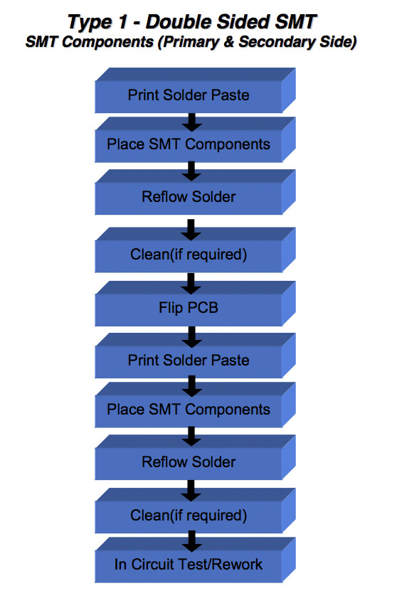
Type 1 – Double Sided SMT
SMT Components (Primary & Secondary Side)

Print Solder Paste Place SMT Components

Reflow Solder

Clean(if required) Flip PCB

Print Solder Paste Place SMT Components

Reflow Solder

Clean(if required) In Circuit Test/Rework

Surface Mount Process 1-14

AI, Auto Insertion : Axial Inserter; Radial Inserter; JW (Jumper Wire) Inserter; Odd form Inserter; PIN inserter; Eyelet Inserter; Terminal Inserter IM, Insertion Mount,MI,Manual Insertion,DIP,  PCB Assembly,Chip Mounter, Pick and Place,  IC Mounter, High Speed Mounter, Wave soldering,LED lighting, LED Lamp, LED Display,  LED tube,UPS, Power Converter, Power Adepter, Mobile Charger, PCB board handling system,  Loader, Unloader, Conveyor,Shuttle,Chip Mounter, Pick and Place, IC Mounter, High Speed Mounter Induction Cooker, AC, Electric Cooker, Fan, TV, Settle Box


Type 2 – Mixed Technology
SMT &Through-Hole Components (Primary Side) Passive SMT Components (Secondary Side )

Surface Mount Process 1-15

Squeegee Aperture Paste

On Contact

Frame

Print Solder Paste Place SMT Components

Reflow Solder

Components

Flip PCB

Place SMT Components

Cure Adhesive Flip PCB Wave Solder Clean (If Needed) Test / Repair

Insert / Clinch Through-Hole

PCB

Apply Adhesive (secondary Side)

AI, Auto Insertion : Axial Inserter; Radial Inserter; JW (Jumper Wire) Inserter; Odd form Inserter; PIN inserter; Eyelet Inserter; Terminal Inserter IM, Insertion Mount,MI,Manual Insertion,DIP,  PCB Assembly,Chip Mounter, Pick and Place,  IC Mounter, High Speed Mounter, Wave soldering,LED lighting, LED Lamp, LED Display,  LED tube,UPS, Power Converter, Power Adepter, Mobile Charger, PCB board handling system,  Loader, Unloader, Conveyor,Shuttle,Chip Mounter, Pick and Place, IC Mounter, High Speed Mounter Induction Cooker, AC, Electric Cooker, Fan, TV, Settle Box


Type 3 – Mixed Technology Through-Hole Components (Primary Side) Passive Surface Mount Components (Secondary Side )

Flip PCB

Place Surface Mount Components

Surface Mount Process 1-16

Insert / Clinch Through-Hole Components (Primary Side)

Apply Adhesive (Secondary Side)

Cure Adhesive Flip PCB Wave Solder Clean (If Needed) Test / Repair

AI, Auto Insertion : Axial Inserter; Radial Inserter; JW (Jumper Wire) Inserter; Odd form Inserter; PIN inserter; Eyelet Inserter; Terminal Inserter IM, Insertion Mount,MI,Manual Insertion,DIP,  PCB Assembly,Chip Mounter, Pick and Place,  IC Mounter, High Speed Mounter, Wave soldering,LED lighting, LED Lamp, LED Display,  LED tube,UPS, Power Converter, Power Adepter, Mobile Charger, PCB board handling system,  Loader, Unloader, Conveyor,Shuttle,Chip Mounter, Pick and Place, IC Mounter, High Speed Mounter Induction Cooker, AC, Electric Cooker, Fan, TV, Settle Box

How to maintain Auto Insertion and SMT machine — ESD Cleaning and Testing Procedures

Procedures and Adjustments

CAUTION

The following procedures explain how to properly clean and test an ESD surface.

Clean an ESD Surface

Do not use abrasive or highly alkaline cleaners on polycarbonate. Never scrape polycarbonate with squeegees, razor blades, or other sharp instruments. Benzene, gasoline, acetone, or carbon tetra chloride should never be used on polycarbonate. Do not clean polycarbonate in the hot sun or at elevated temperatures.

  1. Using a sponge or soft cloth, wash the ESD-protected surface with either a mild detergent or Windex product and lukewarm water.
  2. After washing, rinse with water and dry thoroughly with a chamois or moist cellulose sponge to prevent water spots.
  3. To protect the ESD surface after rinsing and drying,  recommends applying Kleenmaster Brillianize®. This application helps to maintain the static dissipative coating and reduce the accumulation of dust.

Test Static Dissipative Covers

Periodically and after maintenance, check the machine covers to determine if the dissipative qualities of the cover have changed. The following procedure ensures that static dissipative covers are in fact dissipative.

Tooling

Surface resistance meter (such as 3M 701 Surface Resistance meter and probe).

Comments

The surface resistance should be less than 109 ohms in all areas. If the cover package is no longer dissipative, contact you Universal Instruments Corporation sales representative.

Procedure

  1. Clean the static dissipative covers using the Clean ESD Surface procedure to ensure the accuracy of the test.
  2. Using the surface resistance meter, follow the instructions provided by the manufacturer to measure the surface resistance of both the inside and outside of the covers. Measure the resistance at all four corners and at several areas in the middle of the cover. This test checks the integrity of the ESD coating.
  3. Connect the ground path resistance probe to the meter and chassis ground.

The path to the ground should not be higher than the surface resistance. If it is, clean the frame connections, repair loose or corroded fasteners and ground straps, and check tracks for dirt and/or corrosion.

4. Measure the ground path from the covers to the chassis ground. Take this measurement from both surfaces and all four corners of each cover.