This is our Radial Insertion machine offline software, you can learn how to program and operate the machine (password: smthelp.net) (engineer password: 123456 or 12345678)


This is our Radial Insertion machine offline software, you can learn how to program and operate the machine (password: smthelp.net) (engineer password: 123456 or 12345678)

Most of our customers use financing rather than capital outlays to grow their manufacturing business, and they have a number of smart reasons for doing so:
Companies can spend $10k and more a month contracting out their manufacturing, but you can typically bring an SMT assembly line in-house for a third of that when you lease or finance your line, and many companies already have a person on payroll who can operate the equipment.
Financing typically requires fewer internal approvals than a capital purchase, making it the faster and easier route to an assembly line install or upgrade.
Rather than waiting until the money is there for a major capital outlay, with financing you can start the ball rolling on ordering, receiving, and installing your new equipment right away, allowing your company to benefit from increased capacity and capability much sooner than you might have otherwise.
Financing gives you more purchasing power than a cash purchase. This means you can focus more on your goals than your budget.
With a cash purchase comes the temptation to reduce costs, sometimes causing essential aspects like installation and training to be cut, but installation and training can have a big impact on how quickly your new equipment or production line gets up and running. Financing allows you to roll this cost into your payments.
Making a large cash investment in your production line leaves you with less ability to put that money to other strategic uses, such as growing sales and increasing inventory.
With financing, your new equipment becomes a regular monthly expense item in the budget.
At the end of your lease term, equipment can be purchased at fair market value, upgraded, or swapped.

Cut and Clinch Footprints
The cut and clinch cuts the component leads after they are inserted
through the PC board and then clinches them against the underside
of the PC board, securing the component in place.

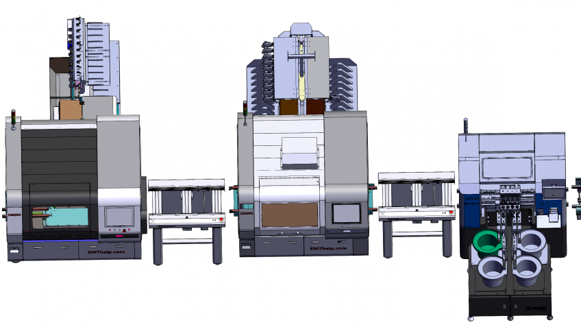

THT Auto Insertion machine
1,Auto Insertion Axial Radial Oddform Production line.html
https://www.smthelp.net/html/Auto%20Insertion%20Axial%20Radial%20Oddform%20Production%20line.html
2,SLD250+S3010A+S7040T(tray feeder)+SULD250
AI machine production line.html
https://www.smthelp.net/html/SLD250+S3010A+S7040T(tray%20feeder)+SULD250%20AI%20machine%20production%20line.html
3,SLD250 S4020A+S3010A SULD250 AI machine
production line.html
https://www.smthelp.net/html/SLD250%20S4020A+S3010A%20SULD250%20AI%20machine%20production%20line.html
4,S7000 Oddform insertion 3 bowl feeder.html
https://www.smthelp.net/html/S7000%20Oddform%20insertion%203%20bowl%20feeder.html
5,S-7040T Oddform insertion w Tray
feeder.html
https://www.smthelp.net/html/S-7040T%20Oddform%20insertion%20w%20Tray%20feeder.html
6,S-7040 Oddform insertion w 4 bowl
feeder.html
https://www.smthelp.net/html/S-7040%20Oddform%20insertion%20w%204%20bowl%20feeder.html
7,Odd form insertion Feeders w
loader-unloader.html
https://www.smthelp.net/html/Odd%20form%20insertion%20Feeders%20w%20loader-unloader.html
Feeder
1,Bowl Radial reel feeder w JUKI cart.html
https://www.smthelp.net/html/Bowl%20Radial%20reel%20feeder%20w%20JUKI%20cart.html
2,JUKI Radial tape L lead feeder .html
https://www.smthelp.net/html/JUKI%20Radial%20tape%20L%20lead%20feeder%20.html
https://www.smthelp.net/html/SMT%20tube%20feeder.html
4,SMT tray feeder -B.html
https://www.smthelp.net/html/SMT%20tray%20feeder%20-B.html
5,SMT label feeder.html
https://www.smthelp.net/html/SMT%20Tray%20feeder.html
6,SMT Tray feeder.html
https://www.smthelp.net/html/SMT%20Tray%20feeder.html
Nozzle
1,SMT nozzle list 1.html
https://www.smthelp.net/html/SMT%20nozzle%20list%201.html
2,Juki Nozzle 500 Assembly.html
https://www.smthelp.net/html/Juki%20Nozzle%20500%20Assembly.html
AI Spare Parts
1, Panasonic AI Spare parts
https://www.smthelp.net/html/Panasonic%20AI%20Spare%20parts%20list%202.html
2,UIC Radial Carrier Clip.html
https://www.smthelp.net/html/UIC%20Radial%20Carrier%20Clip.html
3,UIC Radial Feeder and Carrier Clip (1).html
https://www.smthelp.net/html/UIC%20Radial%20Feeder%20and%20Carrier%20Clip%20(1).html
4,UIC spare parts list 3.html
https://www.smthelp.net/html/UIC%20spare%20parts%20list%203.html
[embeddoc url=”https://www.smthelp.net/wp-content/uploads/2021/04/Southern-Machinery-logo-SMThelp.html” download=”all”]

AI spare parts. PCB handling system.Pick and place machine.SMT nozzles, Assembleon nozzle, NXT nozzle, FUJI nozzle, Hitachi nozzle, JUKI nozzle, KME nozzle, Panasert nozzle, Philips nozzle, Samsung nozzle, Sanyo nozzle, Sony nozzle, Yamaha nozzle, Assembleon nozzle.UNIVERSAL AI SPARE PARTS、UNIVERSAL PARTS,UIC,TDK.VCD .Axial Insertion.AI spare parts
Universal 2596B、Universal 2596C、Universal 6287、Universal 6295 、Universal 9292A 、Universal 6292B、Universal 6292C、Universal 6291、Universal 6293A 、Universal 6293B、 Universal 6293C 、Universal 6241B、 Universal 6241D 、Universal 6241F、 Universal 6348、 Universal 6360A 、Universal 6360B 、Universal 6360D、 Universal 6380A 、Universal 6380B ETC
PANASERT AI: Panasert AVB、Panasert AVF、Panasert AVK、Panasert AVK2、Panasert JV、Panasert JVK、Panasert JVK2、Panasert RH6、Panasert RH2、Panasert RHU、Panasert RH3、Panasert RHS、 RHU AVK2B、Panasert AVK3、Panasert AV131、Panasert RL131、Panasert RG131、Panasert JV131、Panasert RHS2、Panasert RSH2B1.Panasonic, Dynapert, Universal, Sanyo, Sony, Fuji, TDK, KME, Yamaha, Nitto, Philips, Juki, Samsung, Tenryu,


We design and manufacture auto insertion machine,SMT equipment, and providing spare parts support. UNIVERSAL AI SPARE PARTS、UNIVERSAL PARTS,UIC,TDK.VCD SEQUENCER.Axial Insertion.AI spare parts
Universal 2596B、Universal 2596C、Universal 6287、Universal 6295 、Universal 9292A 、Universal 6292B、Universal 6292C、Universal 6291、Universal 6293A 、Universal 6293B、 Universal 6293C 、Universal 6241B、 Universal 6241D 、Universal 6241F、 Universal 6348、 Universal 6360A 、Universal 6360B 、Universal 6360D、 Universal 6380A 、Universal 6380B ETC
PANASERT AI: Panasert AVB、Panasert AVF、Panasert AVK、Panasert AVK2、Panasert JV、Panasert JVK、Panasert JVK2、Panasert RH6、Panasert RH2、Panasert RHU、Panasert RH3、Panasert RHS、 RHU AVK2B、Panasert AVK3、Panasert AV131、Panasert RL131、Panasert RG131、Panasert JV131、Panasert RHS2、Panasert RSH2B1.Panasonic, Dynapert, Universal, Sanyo, Sony, Fuji, TDK, KME, Yamaha, Nitto, Philips, Juki, Samsung, Tenryu,
suppliers, manufacturers, factory, customized,


Electronic Manufacturing
PTH Assembly
Universal 52338901 Motherboard.ATX/ITX/ITX2/MCOS/MVME2100,3100
Tecplam offes fully automatic PTH lines, including radial, axial and jumper wire insertion. We constantly invest in the latest technology machinery,
48820002 Carrier Clip Assembly ,Large Triple Span 5.0/7.5/10.0

SMT-Surface Mount Technology(SMT)
BHS: PCB board handling system, Loader, Unloader, Conveyor,Shuttle
Printer: Solder paste screen printer
SPI: Solder Paste Inspection
Mounter: Chip Mounter, Pick and Place, IC Mounter, High Speed Mounter
AOI Reflow Oven

SMT:FUJI,Siemens,Panasonic,Universal,Assemblon,JUki,Yamaha,Samsung,DEK.ASM

Electronics are an integral part of our daily lives. Everything from our smart phones to our cars includes electronic components. At the heart of these electronics is the printed circuit board, also known as a PCB.
Most people recognize printed circuit boards when they see them. These are the small green chips covered in lines and copper parts you’ll find at the heart of gutted electronic devices. Made with fiberglass, copper lines and other metal parts, these boards are held together with epoxy and insulated with a solder mask. This solder mask is where that characteristic green color comes from.
However, have you ever observed those boards with components solidly stuck on? Never regard them as just decorations of a PCB board. An advanced circuit board won’t be able to give its functionality until components are mounted on it. A PCB with components mounted on is called an assembled PCB and the manufacturing process is called PCB assembly or PCBA for short. The copper lines on bare board, called traces, electrically link connectors and components to each other. They run signals between these features, allowing the circuit board to function in a specifically designed way. These functions range from the simple to the complex, and yet the size of PCBs can be smaller than a thumbnail.
So how exactly are these devices made? The PCB assembly process is a simple one, consisting of several automated and manual steps. With each step of the process, a board manufacturer has both manual and automated options from which to choose. To help you better understand the PCBA process from start to finish, we’ve explained each step in detail below.

The first step of PCB assembly is applying a solder paste to the board. This process is like screen-printing a shirt, except instead of a mask, a thin, stainless-steel stencil is placed over the PCB. This allows assemblers to apply solder paste only to certain parts of the would-be PCB. These parts are where components will sit in the finished PCB.Solder Paste Composition | PCBCart
The solder paste itself is a greyish substance consisting of tiny balls of metal, also known as solder. The composition of these tiny metal balls is 96.5% tin, 3% silver and 0.5% copper. The solder paste mixes solder with a flux, which is a chemical designed help the solder melt and bond to a surface. Solder paste appears as a grey paste and must be applied to the board at exactly the right places and in precisely the right amounts.
In a professional PCBA line, a mechanical fixture holds the PCB and solder stencil in place. An applicator then places solder paste on the intended areas in precise amounts. The machine then spreads the paste across the stencil, applying it evenly to every open area. After removing the stencil, the solder paste remains in the intended locations.

After applying the solder paste to the PCB board, the PCBA process moves on to the pick and place machine, a robotic device places surface mount components, or SMDs, on a prepared PCB. SMDs account for most non-connector components on PCBs today. These SMDs are then soldered on to the surface of the board in the next step of PCBA process.
Traditionally, this was a manual process done with a pair of tweezers, in which assemblers had to pick and place components by hand. These days, thankfully, this step is an automated process among PCB manufacturers. This shift occurred largely because machines tend to be more accurate and more consistent than humans. While humans can work quickly, fatigue and eyestrain tends to set in after a few hours working with such small components. Machines work around the clock without such fatigue.Surface Mount Technology | PCBCart
The device starts the pick and place process by picking up a PCB board with a vacuum grip and moving it to the pick and place station. The robot then orients the PCB at the station and begins applying the SMTs to the PCB surface. These components are placed on top of the soldering paste in preprogrammed locations.

Once the solder paste and surface mount components are all in place, they need to remain there. This means the solder paste needs to solidify, adhering components to the board. PCB assembly accomplishes this through a process called “reflow”.
After the pick and place process concludes, the PCB board is transferred to a conveyor belt. This conveyor belt moves through a large reflow oven, which is somewhat like a commercial pizza oven. This oven consists of a series of heaters which gradually heat the board to temperatures around 250 degrees Celsius, or 480 degrees Fahrenheit. This is hot enough to melt the solder in the solder paste.
Once the solder melts, the PCB continues to move through the oven. It passes through a series of cooler heaters, which allows the melted solder to cool and solidify in a controlled manner. This creates a permanent solder joint to connect the SMDs to the PCB.
Many PCBAs require special consideration during reflow, especially for two-sided PCB Assembly. Two-sided PCB assembly need stenciling and reflowing each side separately. First, the side with fewer and smaller parts is stenciled, placed and reflowed, followed by the other side.
tep 4: Inspection and Quality Control

Once the surface mount components are soldered in place after the reflow process, which doesn’t stand for completion of PCBA and the assembled board needs to be tested for functionality. Often, movement during the reflow process will result in poor connection quality or a complete lack of a connection. Shorts are also a common side effect of this movement, as misplaced components can sometimes connect portions of the circuit that should not connect.
Checking for these errors and misalignments can involve one of several different inspection methods. The most common inspection methods include:
• Manual Checks: Despite upcoming development trend of automated and smart manufacturing, manual checks are still relied on in PCB assembly process. For smaller batches, an in-person visual inspection by a designer is an effective method to ensure the quality of a PCB after the reflow process. However, this method becomes increasingly impractical and inaccurate as the number of inspected boards increases. Looking at such small components for more than an hour can lead to optical fatigue, resulting in less accurate inspections.
• Automatic Optical Inspection: Automatic optical inspection is a more appropriate inspection method for larger batches of PCBAs. An automatic optical inspection machine, also known as an AOI machine, uses a series of high-powered cameras to “see” PCBs. These cameras are arranged at different angles to view solder connections. Different quality solder connections reflect light in different ways, allowing the AOI to recognize a lower-quality solder. The AOI does this at a very high speed, allowing it to process a high quantity of PCBs in a relatively short time.
• X-ray Inspection: Yet another method of inspection involves x-rays. This is a less common inspection method — it’s used most often for more complex or layered PCBs. The X-ray allows a viewer to see through layers and visualize lower layers to identify any potentially hidden problems.
The fate of a malfunctioning board depends on PCBA company’s standards, they will be sent back to be cleared and reworked, or scrapped.
Whether an inspection finds one of these mistakes or not, the next step of the process is to test the part to make sure it does what it’s supposed to do. This involves testing the PCB connections for quality. Boards requiring programming or calibration require even more steps to test proper functionality.
Such inspections can occur regularly after the reflow process to identify any potential problems. These regular checks can ensure that errors are found and fixed as soon as possible, which helps both the manufacturer and the designer save time, labor and materials.
Thru-Hole Technology (THT) Assembly Process

As a traditional PCB assembly method, thru-hole mounting process is accomplished through collaboration of manual procedure and automatic procedure.
• Step 1: Components Placement – This step is achieved manually by professional engineering staff. Engineers need to quickly, yet precisely place components on corresponding positions based on client’s PCB design files. Component placement must conform to regulations and operation standards of thru-hole mounting process to guarantee high quality end products. For example, they have to clarify polarity and orientation of components, to stop operating component from affecting ambient components, to make completed component placement compatible with corresponding standards and to wear anti-static wristbands when dealing with static-sensitive components like ICs.
• Step 2: Inspection & Rectification – Once component placement is completed, the board is then placed in a matching transport frame where board with components plugged in will be automatically inspected so as to determine whether components are accurately placed. If issues concerning component placement are observed, it’s easy to get them rectified immediately as well. After all, this takes place prior to soldering in PCBA process.
• Step 3: Wave Soldering – Now the THT components should be accurately soldered onto circuit board. In the wave soldering system, the board moves slowly over a wave of liquid solder at high temperature, approximately 500°F. Afterwards, all leads or wires connections can be successfully obtained so that thru-hole components are firmly attached to the board.
Surface Mount Technology (SMT) Assembly Process
Compared with thru-hole mounting process, surface mounting process stands out in terms of manufacturing efficiency because it features a totally automatic mounting PCB assembly process from solder paste printing, pick and place and reflow soldering.
• Step 1: Solder Paste Printing – Solder paste is applied on the board through a solder paste printer. A template ensures that solder paste can be accurately left on correct places where components will be mounted, which is also called stencil or solder screen. Because quality of solder paste printing is directly associated with quality of soldering, PCBA manufacturers focusing on high quality products usually carry out inspections after solder paste printing through a solder paste inspector. This inspection guarantees printing has achieved regulations and standards. If defects are found on solder paste printing, printing has to be reworked or solder paste will be washed off prior to second printing.
• Step 2: Components Mounting – After coming out of solder paste printer, PCB will be auto-sent to pick-and-place machine where components or ICs will be mounted on corresponding pads in the effect of tension of solder paste. Components are mounted on PCB board through component reels in the machine. Similar to film reels, component reels carrying components rotate to provide parts to the machine, which will quickly stick parts to the board.
• Step 3: Reflow Soldering – After every component is placed, the board passes through a 23-foot-long furnace. A temperature of 500°F causes the solder paste to liquefy. Now the SMD components are bound firmly to the board.
THT – Through Hole Technology (AI)
PCB Electronic manufacturing
THT PCB Assembly auto insertion machine.
AI, Auto Insertion : Axial Inserter; Radial Inserter; JW (Jumper Wire) Inserter; Odd form Inserter; PIN inserter; Eyelet Inserter; Terminal Inserter
IM, Insertion Mount,
MI,Manual Insertion,
DIP Wave soldering
SMT-Surface Mount Technology(SMT)
BHS: PCB board handling system, Loader, Unloader, Conveyor,Shuttle
Printer: Solder paste screen printer
SPI: Solder Paste Inspection
Mounter: Chip Mounter, Pick and Place, IC Mounter, High Speed Mounter
AOI Reflow Oven
Shenzhen Southern Machinery Sales and Service Co.,Ltd
Add :Rm 1806,Block 3, Jinyun COFCO, Qianjin 2 Road,Xixiang,Baoan District, Shenzhen City, China
TEL: 0755-83203237; FAX:0755-23240492 website:www.smthelp.net whatsapp:+86 137 6048 1664 shaoyong@smthelp.net

45798407 Tube Continuity
45798406 Tube Continuity
45798405 Tube Continuity
45798404 Tube Continuity
45798403 Tube Continuity
45798402 Tube Continuity
45798401 Tube Continuity
Preventive Maintenance Schedule
WARNING Do not perform any preventive maintenance with power on unless specifically instructed otherwise. Failure to observe this warning may result in personal injury.
CAUTION When performing machine maintenance, wear a wrist strap connected to ground to prevent electrostatic discharge damage to printed circuit boards.
500,000 Cycles Check: Perform Maintenance:
3,000,000 Cycles Check: Perform Maintenance:
12,000,000 Cycles Check: Perform Maintenance:
Check for worn cutters and bushings on 1. Replace if necessary. the cut and clinch by observing the quality of the production board component leads. 2. Lubricate the clinch lead screw with Super Blue (BLKM07680). 3. Replace the O-rings and bumpers in the cutter cylinders on the cut and clinch assembly. 4. Lubricate the three surfaces of the notch in the rocker guide Kendall Super Blue (BLKM07680).
48,000,000 Cycles Check: Perform Maintenance: 1. Lubricate the anvil slides with Kendall Super Blue (40833838) and grease gun (47408201).


Reflow oven technology and precautions
Far infrared reflow again
In 80s the use of far infrared reflow has the characteristics of fast heating, energy saving, stable operation, but because the printed circuit board and various components for different material, color and thermal radiation absorption rate to have very big difference, caused by a variety of different components and different parts of the circuit temperature is not uniform, the local temperature difference. For example, the black plastic package of integrated circuit will be overheated due to the high radiant absorption rate, and the welding part of it will lead to false welding on the silver lead instead of low temperature. In addition, the heat radiation blocked on printed boards, such as welding pins or small components in the shadow parts of big (high) components, will cause poor welding due to insufficient heating.
1.2 full hot air reflow again
Full hot air reflow oven is a welding method by which the flow of airflow is forced through a convective nozzle or a heat-resistant fan, so that the welded parts are heated. This kind of equipment began to rise in 90s. Due to the adoption of this heating mode, the temperature of PCB and components is close to the temperature of the given heating area, which completely overcomes the temperature difference and shadowing effect of infrared reflow soldering, so it is widely applied now. In all hot air reflow oven equipment, the convection velocity of the circulating gas is very important. In order to ensure that the circulating gas acts on any area of the printed board, the air flow must have a fast enough speed. To a certain extent, it is easy to cause the jitter of the printed board and the displacement of the components. In addition, in terms of heat exchange, the efficiency is poor and the power consumption is more.
1.3 infrared hot air reflow again
This kind of reflow oven is a more ideal heating method, which is based on the IR oven with hot air to make the temperature even more uniform insaide the oven. The characteristics of this kind of equipment to make full use of the infrared penetration, high thermal efficiency, energy saving, and effectively overcome the temperature difference of infrared reflow soldering and shadowing effect, and make up the influence of hot air reflow on gas flow caused by excessive demand, therefore at international this kind of IR+Hot reflow is used most commonly at present .
With the increase of assembly density and the appearance of fine spacing assembly technology, a reflow oven furnace with nitrogen protection has appeared. Welding under nitrogen protection conditions can prevent oxidation, improve welding wetting power and speed up wetting speed. It is more suitable for uncleaning process to reduce the welding force and reduce welding beads.
2 The establishment of temperature curve
The temperature curve is the curve of the temperature of a point on the SMA will change over time when SMA through the reflow oven. The temperature curve provides an intuitive method to analyze the temperature change of a component during the whole reflow process. This is very useful for obtaining the best weldability, avoiding damage to the components due to overheating, and ensuring the quality of the welding.
The following is a brief analysis of the preheating section.
2.1 preheating section
The purpose of this section is to put PCB at room temperature as soon as possible heating, to achieve second specific targets, but the heating rate should be controlled in the appropriate range, if excessive, will produce thermal shock, circuit boards and components may be damaged; if too slow, will not fully solvent, affecting the welding quality. Due to the rapid heating rate, the temperature difference in the rear section of the temperature zone is larger than that in the SMA. In order to prevent the damage of thermal shock to the component, the maximum speed is 4℃/s. However, the normal rise rate is set to 1-3℃/s. The typical heating rate is 2℃/s.
2.2 heat preservation section
The heat preservation section is the area where the temperature rises from 120℃-150℃ to the melting point of the solder paste. Its main purpose is to make the temperature of each element in the SMA stable and minimize the temperature difference.In this area, the temperature of the larger components can have enough time to catch up with the smaller components and ensure that the flux in the solder paste is fully volatile. The oxide of the soldering plate, the solder ball and the pin of the element is removed, and the temperature of the entire circuit board is balanced until the end of heat preservation section. It should be noted that all elements on the SMA should have the same temperature at the end of heat preservation section, otherwise, entering the reflux section will cause various bad welding phenomena due to the uneven temperature of each part.
2.3 reflow section
In this area, the temperature of the heater is set to the highest, which makes the temperature of the component up to the peak temperature. In reflow sectionthe,the different of peak temperature is according to the solder paste to change, the general recommendation for solder melting point temperature plus 20-40℃. For 63Sn/37Pb solder paste with melting point of 183℃ and Sn62/Pb36/Ag2 solder paste with melting point of 179℃, the peak temperature is generally 210-230℃. Reflow time should not be too long to prevent adverse effects on SMA. The ideal temperature curve is the smallest area covered by the “tip zone” of the solder melting point.


| 40075420 O-RING |
| 47104702 MOTOR:BRUSHLESS:DC:ENCDR |
| 47405502 SWITCH BRACKET |
| 47636701 COUPLING |
| 49752203 LEAD SCREW, HEAD |
| 47898701 FORMER, R INSIDE |
| 47898801 FORMER,L INSIDE |
| 80031922 MSDP 1.5MM X 8MM |
| 52924402 PUSHER, PRECISION |
| 48241402 SPRING, COMPRESSION |
| 53069001 MSHCS M2 X 10MM |
| 52924701 BEARING, HOLDER SPRING |
| 52946001 BEARING, SQUARE HOLDER |
| 52924501 HOLDER,PRECISION INS PAD |
| BLKM06303 RET RING 5100-12 |
| 47631004 CAM,30/135 CENTERING |
| 46442715 BELT,TIMING |
| 23502002 PAD |
| 40075420 O-RING |
| 40520201 GO-RINGS |
| 47405502 SWITCH BRACKET |
| 47307703 CONTINUITY CABLE ASSY |
| 30953801 PIN |
| 30997611 PUSHER |
| 42502304 HOLDER #44Ñ PUSHER TIP |
| 42502403 ACTUATOR ARM |
| 48241402 SPRING COMPRESSION |
| 41631401 SPRING COMPRESSION |
| 52344901 GUIDE JAW |
| 45729304 RED |
| 47356403 BLACK |
| 47356404 BLUE |
| 47356405 BEIGE |
| 40833022 FUSE |
| BLKE01244 FUSE |
| BLKE01241 FUSE |
| BLKE01251 FUSE |
| BLKE01234 FUSE |


