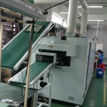
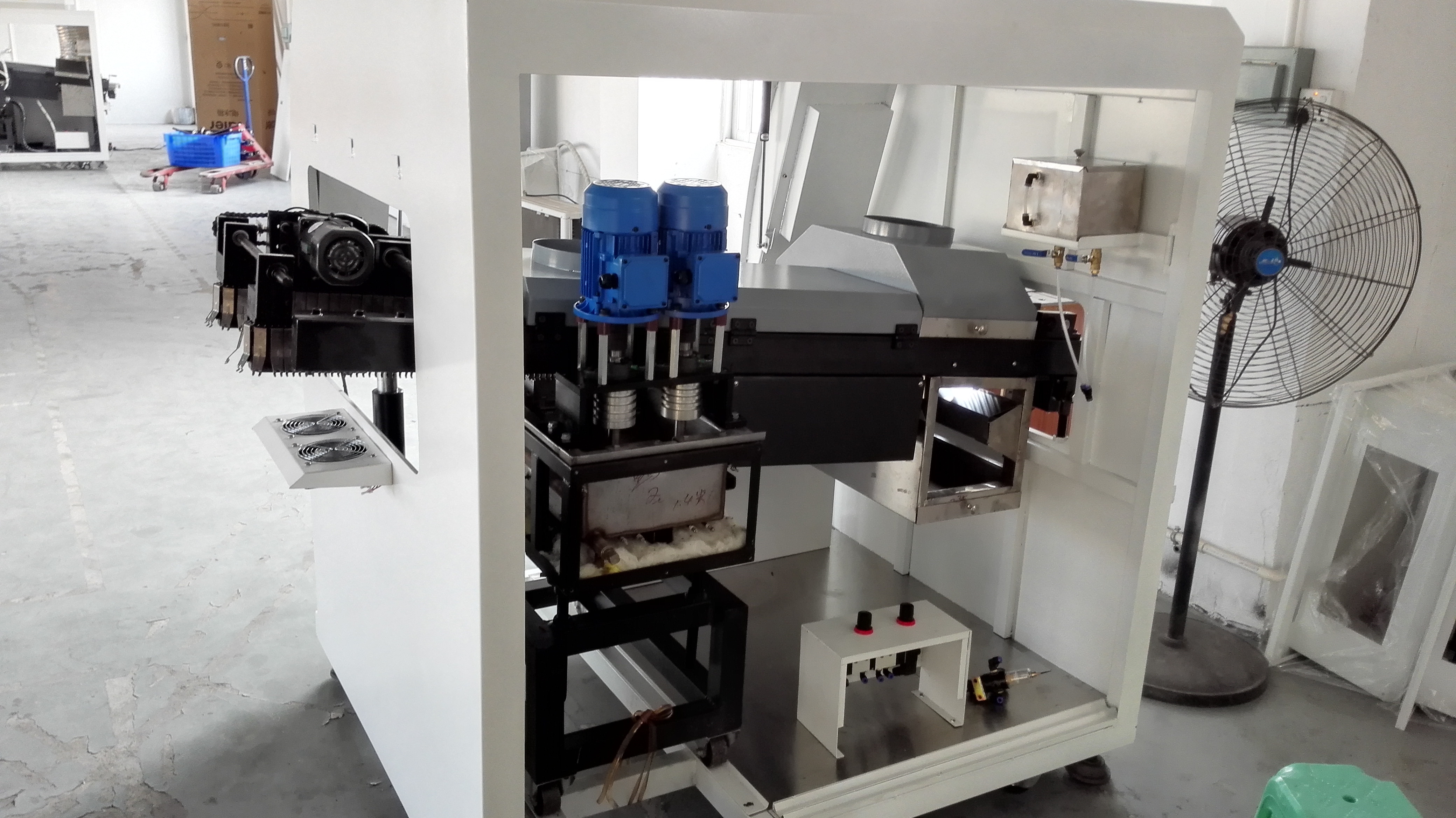
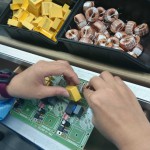
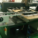
PCBA Quality Process Audit — Wave soldering machine

1. Work Instructions
1.1 Is there a revision controlled Operator Work Instruction which contains set-up information for the specific product being processed? (Score 0 if any unsigned/undated handwritten instructions or any handwritten instructions more than 48 hrs old)
1.2 Are Work Instructions readily available to the operator and are they followed at Wave?
1.3 Do Set-Up Sheets specify the Solder, the Flux, and the thinners (as applicable) to be used?
1.4 Do Set-Up Sheets specify the Spray Flux parameter settings such as delay, duration, traverse speed, pressure, etc?
1.5 Do Set-Up Sheets specify the Pre-Heater set points and the Solder Pot Temperature and are they the same as those on the machine?
1.6 Do Set-Up Sheets specify the Conveyor Speed and is it the same as that in the program?
1.7 Do Set-Up Sheets specify the Lead Clearance and is it the same as that set by the machine?
1.8 Do Set-Up Sheets specify Wave Type (Chip/Lambda/Omega) to be used?
1.9 Do Set-Up sheets specify the Solder Pot Hot Air Knife Pressure and Temperature settings?
1.10 Do Set-Up sheets specify if the Finger Cleaner must be on? No Finger Cleaner = 0
1.11 Is the machine Program Name specified on the Work Instruction or set-up sheets?
1.12 Do the all the above wave parameter settings correspond to those settings on the machine?
1.13 Are Generic Wave Set-Up Parameters documented? These are the parameters which are not changed for product changeovers.
1.14 Do these Generic Wave Set-Up Parameters include, pressure settings, conveyor angle, etc.
2. Machine Capability
2.1 Is the flux application technology in use suitable for the product being built?
2.2 Is the wave technology in use suitable for the product being built in terms of the ability control critical parameters to achieve desired results?
2.3 Does the wave use a top side pre-heater to ensure PTH barrel fill meets IPC 610 specs given the mass of the board, carrier, and the top hat?
2.4 Are air flow controllers or a centralized control system used to balance exhaust flow rates for each individual exhaust drops?
2.5 Are exhaust flow rate ranges specified and monitored on a regular basis to insure compliance?
2.6 Is Automatic Wave Height control installed to control the laminar wave height?
2.7 Is there a Solder Pot Hot Air Knife installed and used on the wave equipment?
2.8 Is there an automatic Finger Cleaner installed and used on the wave equipment with an appropriated cleaning fluid? No FC = 0
2.9 Is the machine Program Name revision controlled to show traceability of program changes?
2.10 Is the machine Program Name traceable to the PCB and PCBA part number?
2.11 Is access to the machine program password protected with restricted access?
2.12 Do program changes to critical parameters during machine control remain unsaved unless approved by a technician/engineer?
2.13 Is the safety equipment and protective clothing provided adequate and are they used? Must include boots, apron, gloves, face shield, etc
3. Flux Application
3.1 Is flux applied using either a fixed nozzle or moving nozzle spray application method? Any other application method = 0
3.2 Can the sequence of; detection, delay, trigger, duration, and stop, be clearly explained by a technician? Other method = 0
3.3 Is the detection, delay, trigger, duration, and stop, controls performing as expected? Other method = 0
3.4 Is there a feedback link between the conveyor speed and the flux applicator to auto-compensate for changes? Other method = 0
3.5 Is there an automatic sensor that indicates when a flux drum is near empty?
3.6 Is there a method to determine if the quantity of flux applied to the board to ensure it adequate? Not too much and not too little.
3.7 Is there a test used to check the coverage of flux applied to the board to ensure it is sufficient?
4. Wave Set-Up
4.1 Has specifying the Solder Pump Speed value been discontinued as a way to achieve the desired Wave Height?
4.2 Is the relationship between Wave Height set-up and Contact Area/Length known for the product being processed?
4.3 Is there a Quartz Plate available to verify Contact Area/Length achieved for the board being processed?
4.4 Is the documented Contact Area/Length being achieved for the Wave Height set-up used?
4.5 Does the shape of the Contact Area indicate parallelism?
4.6 Does the Contact Length coupled with the Conveyor Speed, achieve the documented dwell time requirement?
4.7 Is there evidence that Contact Area/Length and shape verified after Solder Pot removal and replacement, and maintenance?
4.8 Is there evidence that the Contact Area/Length and shape verified on addition of solder or on adjustment of lead clearance?
4.9 Does the board/pallet exit the Solder Pot in the stagnant area for the set conveyor angle and lead clearance?
4.10 Are all conveyor Fingers in a good state of repair?
4.11 Is the quantity, type and spacing of each Finger design defined for the conveyor?
4.12 Has the pot been set up to run with an intermittent wave so as to reduce dross build up? If gap between subsequent PCBAs too small, score 1
4.13 Does the level of Dross in the pot suggest that the pot is dedrossed at least once every 8 hours?
5. Temperature Profile
5.1 Is there available a Temperature Profile for the product currently being built?
5.2 Is the Temperature Profile assessable and readily available to operators / technicians as and when required?
5.3 Were the Pre-Heat Set Points, Conveyor Speed, and Solder Temperature logged for that Thermal Profile when it was conducted?
5.4 Do the Set Points, Conveyor Speed & Solder Temp written on the Thermal Profile correspond to the current Machine settings?
5.5 Is there available an Engineering based specification to detail the acceptable process window for Temperature Profiles?
5.6 Was the Engineering based spec. derived from the Flux manufacturer’s recommendations but controls to a narrower window?
5.7 Does the product Temperature Profile fall within the Engineering based specification for the process window?
5.8 Does the product Temperature Profile fall within the Engineering based specification for glass transition temperature requirements?
5.9 Can any excursions outside of the process window be justified and supported with hard evidence and logical analysis?
5.10 Does the product Temperature Profile meet the requirements of the SMT components already attached to the PCBA?
5.11 Are the boards used to establish the initial Thermal Profile kept as engineering samples?
5.12 Have at least five thermocouples been used at various points on the board to establish the Thermal Profile? Note*
5.13 Is there a documented and systematic approach used to identify the most appropriate locations to attach the thermocouples?
5.14 Is there evidence that each thermocouple ball was bonded to a board joint using Hi Temp. Solder or Conductive Epoxy?
5.15 Is the top side Temperature Profile low enough to prevent secondary reflow? Must be below 160 degrees C.
5.16 Has a Calibration Profile been established in order to detect machine long term performance degradation?
5.17 Is there a documented frequency for running a Calibration Profile and was it established based upon historical performance data?
5.18 Is there evidence to demonstrate that Calibration Profiles are conducted and that records are up-to-date?
5.19 Is the practice of comparing the current Calibration Profile to the Standardized Calibration Profile used to identify changes?
5.20 Is the current Calibration Overlay/Profile used to determine if a variation in the wave’s thermal characteristics has occurred?
5.21 Is the current Calibration Overlay/Profile used to determine if a variation in conveyor speed has occurred?
5.22 Is there evidence to demonstrate that action was taken when the Calibration Profile was different to the Standard?
5.23 Is a standardized tool, like a WaveRider, used with a standardized profile to conduct a Calibration Profile?
6. Solder Analysis
6.1 Is there a documented frequency for conducting Solder Analysis and was this frequency established based upon historical results?
6.2 Is there evidence to demonstrate that Solder Analysis records are up-to-date?
6.3 Does the Solder Analysis results suggest that contaminants in the solder pot are within acceptable levels?
6.4 Is there evidence to demonstrate that action was taken when Solder Analysis results were unsatisfactory?
7. Manual Inspection
7.1 Are outputted boards at least sample inspected post wave for wave solder defects as part of machine performance control?
7.2 Are Workmanship Standards defined for soldering, and are they accessible so that machine performance can be measured accurately?
7.3 Is Defect Density Charting used to identify the common location of defects so that actions may be take to eliminate them? This may include addition of solder thieves, pallet/carrier modification, etc.
7.4 Is there evidence of the use of at least sampling X-ray to ensure via penetration and barrel fill are to acceptable standards?

PCBA Quality Process Audit — Manual Assembly

1. Work Instructions Enter 1 or 0. NA may be a valid response for shaded cells.^
1.1 Are revision controlled Work Instructions displayed for the operator at each assembly station? (Score 0 if any unsigned/undated handwritten instructions or any handwritten instructions more than 48 hrs old)
1.2 Are component part numbers and their descriptions specified on Work Instructions?
1.3 Are component descriptions sufficiently detailed to ensure the correct component is being used?
1.4 Are the reference designators and the quantity per part number specified on Work Instructions?
1.5 Is component polarity or its non-existence consistently and unambiguously specified on Work Instructions?
1.6 Are the components on the Work Instructions listed by the most appropriate order of insertion?
1.7 Is the layout of lin bins/trays defined on Work Instructions for each assembly station?
1.8 Are all lin bins/trays located in the correct position as per Work Instructions for each assembly station?
1.9 Do Work instructions indicate if solder pallets/carriers or breakers must be used?
1.10 Do Work instructions indicate if a top hat, separators, plugs, Kapton tape, finger protection, etc. must be used?
1.11 Does the direction of build for the board align with the orientation of the board on the Work Instructions and Wave direction?
1.12 Do Work Instructions not only indicate what components need to be inserted but also the buddy check components?
1.13 Is the conveyor at entry to the wave, slower than the wave conveyor speed, and documented on Work Instructions?
1.14 Is there a documented process for the identification and control of non-completed boards resulting from breaks, shift changes, etc.
1.15 Is the PWB part number and Revision specified on the Work Instruction or line set-up instructions?
1.16 Does the PWB part number and Revision cross-reference to the PCBA part number and Revision?
2. Station Breakout 1, 2 3, 4 5, 6 7, 8 9, 10 Actual
2.1 Is there a document available which describes the guidelines for station breakout at Manual Assembly?
2.2 Has the number of assembly stations required been determined scientifically in order to maximize throughput within constraints?
2.3 Is there evidence that the line is evenly balanced with the defined number of stations and the defined station breakout?
2.4 Is there evidence to demonstrate that the assembly operators follow the defined station breakout on the Work instructions?
2.5 Is there evidence that sufficient time is allocated for component insertion at each station, as determined by the beat rate of the line?
2.6 Does following the breakout ensure that the insertion of subsequent components is not restrictive or increased in difficulty?
2.7 Does following the breakout ensure that ‘snap-in’ type components are inserted first or off-line?
2.8 Does following the breakout ensure that components that ‘look’ alike are assembled at different and non-adjacent stations where possible?
2.9 Does following the breakout ensure that components that ‘fit’ alike are assembled at different and non-adjacent stations, where possible?
3. Line Set-Up and Verification 1, 2 3, 4 5, 6 7, 8 9, 10 Actual
3.1 Are all Manual Assembly station set-ups verified according to Work Instructions and a log signed prior to start-up http://xanaxonlinebuy.com & re-start?
3.2 Are first-built boards verified against documentation for missing components, value, and for correct polarity pre Wave?
3.3 Are the components supplied to Manual Assembly appropriately prepped with correct lead length, forming and pitch, etc.?
3.4 Is it evident that lead snipping has been minimized through adequate component prep and/or pallet support design?
3.5 Are all totes or tray locations identified with printed part numbers, descriptions, circuit designators, station number, and/or layout information?
3.6 Are boards conveyed along the line automatically without the need to manually push the board forward or pull the board back?
4. Tooling 1, 2 3, 4 5, 6 7, 8 9, 10 Actual
4.1 Is tooling used to provide underside support on all sides, to minimize flexing, for the insertion of components that require a force or snap-in fit?
4.2 Is tooling used and is it adequate to prevent board flexing during all component insertion?
4.3 Is tooling used for snap-in components prone to bent pins, to verify the pin straightness prior to their insertion?
4.4 Is there a document available which describes the guidelines for pallet/carrier design?
4.5 Are footprint, co-planarity, depth below datum, ID, clamping mechanisms, chamfering, direction of flow, criteria addressed?
4.6 Are pallets/carriers identified by a name or tooling number which is traceable to the PCBA part number and revision?
4.7 Is pallet/carrier orientation to the line specified or indicated and correct?
4.8 Are pallets/carriers designed such a way that they support all non-snap-in components without the use of weights?
4.9 Are pallets/carriers appropriately milled out to avoid shadowing and insufficients?
4.10 Do selective wavesolder pallets/carriers use built in solder thieves to help reduce the occurrence of solder bridging?
4.11 Is there a documented requirement to clean pallets/carriers and to regularly inspect them for damage and is there evidence of this?
4.12 Are pallets/carriers in a good state of repair, clean, and satisfactorily stored to prevent damage?
5. Manual Inspection 1, 2 3, 4 5, 6 7, 8 9, 10 Actual
5.1 Are outputted boards 100% inspected pre wave (Top Side) for missing components, value and polarity?
5.2 Is there evidence to demonstrate that this quality inspection is conducted?
5.3 Is there a visual aid (hard copy or otherwise) which identifies the populated locations with polarity, and also the no-pop locations?
5.4 Is there a buddy check system used between stations to ensure the previous operation has been fully completed?
5.5 Is there evidence to demonstrate that a buddy check system is deployed between assembly stations?
5.6 Is the touch method used as part of the buddy system?
5.7 Are manually inserted components that are not tested by ICT specifically targeted for inspection in addition to the buddy check?
5.8 Is there evidence to demonstrate that at least an hourly defect feedback process to Manual Assembly is in operation and effective?
5.9 Is accountability for Manual Assembly defects traceable to a specific workstation and operator/supervisor?
5.10 Are snap-in connectors inspected for bent pins post-insertion? (Tooling or an alternate method with proven effectiveness must be used).
Maximum Score 53 53 53 53 53 53
Score Obtained 0 0 0 0 0 0
Score Percentage 0%
Pass Percentage 80% 80% 80% 80% 80% 80%
Outcome Not Audited Not Audited Not Audited Not Audited Not Audited Not Audited
AI spare parts、Universal Parts,UIC,TDK.VCD Sequencer.SMT,THT,PCB,PCBA,AI,wave soldering,reflow oven,nozzle,feeder,wave soldering,PCB Assembly, LED, LED lamp, LED display,

SMT Pick And Place machine Spare parts

We can supply smt machine parts, smt spare parts, replacement parts for pick and place machine, Brands including FUJI, SIEMENS, PANASONIC, JUKI, YAMAHA, , etc.


Part of product list: 

Compatible for

Part name

Part No.

Usage

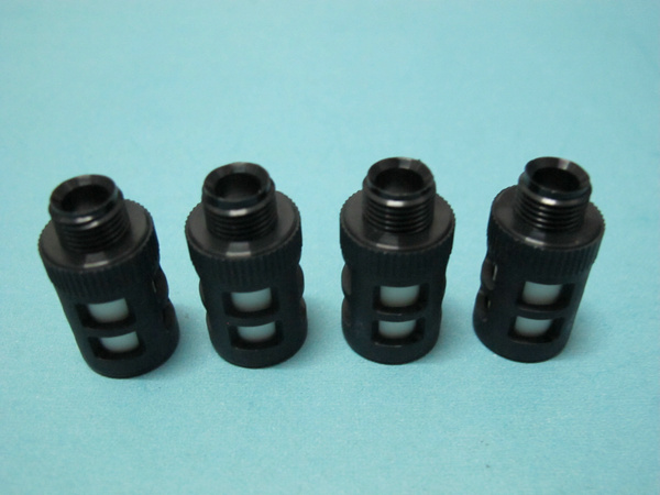
fuji NXT H01

H01 Filter (with plastic BKT)

AA1FZ01

Consumable parts

fuji NXT H12

H12 Filter (with plastic BKT)

AA19H02

Consumable parts

fuji NXT H01

H01 smt filter

XH00560

Consumable parts

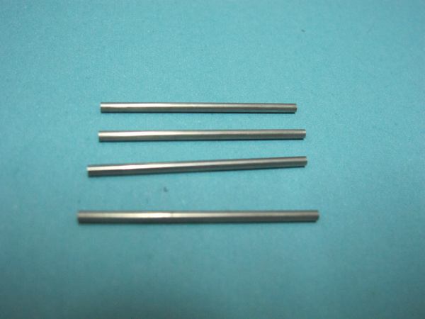
fuji

smt pin thick pin

ADCQK8010

replacement parts

fuji

smt pin thin pin

ADCQK8010

replacement parts

fuji XP243

XP243 U axis PULLEY

AGFTR8220

replacement parts

fuji XP243

XP243 U axis PULLEY

AGFTR8230

replacement parts

fuji

fuji sliding block and thimble

O0186

replacement parts

fuji CP6

CP6 HOLDER

AWPH3110

replacement parts

fuji CP43

CP43 CLUTCH

MPH0501

replacement parts

fuji QP242

QP242 Filter

H3022T

Consumable parts

fuji CP41

CP41 press button

O0191

replacement parts

fuji IP3

IP3 Filter

H30215

Consumable parts

fuji CP6

cylinder

WPA5150

Consumable parts

fuji CP7 CP8

smt filter

DCPH3780

Consumable parts


AI spare parts、Universal Parts,UIC,TDK.VCD Sequencer.SMT,THT,PCB,PCBA,AI,wave soldering,reflow oven,nozzle,feeder,wave soldering,PCB Assembly, LED, LED lamp, LED display,
H10212
angela@smthelp.net

AI spare parts、Universal Parts,UIC,TDK.VCD Sequencer.SMT,THT,PCB,PCBA,AI,wave soldering,reflow oven,nozzle,feeder,wave soldering,PCB Assembly, LED, LED lamp, LED display,
H13362
angela@smthelp.net

AI spare parts、Universal Parts,UIC,TDK.VCD Sequencer.SMT,THT,PCB,PCBA,AI,wave soldering,reflow oven,nozzle,feeder,wave soldering,PCB Assembly, LED, LED lamp, LED display,
H30105
angela@smthelp.net

AI spare parts、Universal Parts,UIC,TDK.VCD Sequencer.SMT,THT,PCB,PCBA,AI,wave soldering,reflow oven,nozzle,feeder,wave soldering,PCB Assembly, LED, LED lamp, LED display,
H42693
angela@smthelp.net

AI spare parts、Universal Parts,UIC,TDK.VCD Sequencer.SMT,THT,PCB,PCBA,AI,wave soldering,reflow oven,nozzle,feeder,wave soldering,PCB Assembly, LED, LED lamp, LED display,
K1006L COUPLING
angela@smthelpl.com

AI spare parts、Universal Parts,UIC,TDK.VCD Sequencer.SMT,THT,PCB,PCBA,AI,wave soldering,reflow oven,nozzle,feeder,wave soldering,PCB Assembly, LED, LED lamp, LED display,
H3022T
angela@smthelp.net

AI spare parts、Universal Parts,UIC,TDK.VCD Sequencer.SMT,THT,PCB,PCBA,AI,wave soldering,reflow oven,nozzle,feeder,wave soldering,PCB Assembly, LED, LED lamp, LED display,
H3022L
angela@smthelp.net

AI spare parts、Universal Parts,UIC,TDK.VCD Sequencer.SMT,THT,PCB,PCBA,AI,wave soldering,reflow oven,nozzle,feeder,wave soldering,PCB Assembly, LED, LED lamp, LED display,
H2002Y
angela@smthelp.net

AI spare parts、Universal Parts,UIC,TDK.VCD Sequencer.SMT,THT,PCB,PCBA,AI,wave soldering,reflow oven,nozzle,feeder,wave soldering,PCB Assembly, LED, LED lamp, LED display,
GFPH2540
angela@smthelp.net

AI spare parts、Universal Parts,UIC,TDK.VCD Sequencer.SMT,THT,PCB,PCBA,AI,wave soldering,reflow oven,nozzle,feeder,wave soldering,PCB Assembly, LED, LED lamp, LED display,
GFPN1160
angela@smthelp.net

AI spare parts、Universal Parts,UIC,TDK.VCD Sequencer.SMT,THT,PCB,PCBA,AI,wave soldering,reflow oven,nozzle,feeder,wave soldering,PCB Assembly, LED, LED lamp, LED display,
H1124D
angela@smthelp.net

AI spare parts、Universal Parts,UIC,TDK.VCD Sequencer.SMT,THT,PCB,PCBA,AI,wave soldering,reflow oven,nozzle,feeder,wave soldering,PCB Assembly, LED, LED lamp, LED display,
A10397
angela@smthelp.net

AI spare parts、Universal Parts,UIC,TDK.VCD Sequencer.SMT,THT,PCB,PCBA,AI,wave soldering,reflow oven,nozzle,feeder,wave soldering,PCB Assembly, LED, LED lamp, LED display,
2MGKCF001600
angela@smthelp.net
XS01802=XS03693 SPOOL NXT 原装全新..

China SMT pick and Place / Auto Insertion machine Import Exp ort Statistics 2015

China SMT pick and Place / Auto Insertion machine Import Export Statistics 2015
Import Data
Duration Product Name Qty (Set) Price (usd) Qty Average Monthly M/C Price Average
Jan~Nov 2015 Pick and Place M/C 7551 1092061772 686 US$144,625
Export Data
Jan~Nov 2015 Pick and Place M/C 2119 81448484 193 US$38,437
Import Data
Jan~Nov 2015 Auto Insertion M/C 332 45353734 30 US$136,608
Export Data
Jan~Nov 2015 Auto Insertion M/C 235 6538941 21 US$27,825
Data from: http://www.customs-info.com/Trade/Commodity.aspx

Panasonic vs Universal Radial Insertion machine for PCB Through Hole assembly

Panasonic Radials

About Panasonic

Panasonic is a division of Matsushita (Japan), one of the largest companies in the world. They are highly vertically integrated in that they manufacture Radial componentry, Radial insertion equipment and end products with PCB’s populated with Radial components (consumer electronics, for example). This structure affords them some advantages and disadvantages. The advantages include:

  1. first hand experience using equipment,
  2. in-house production testing prior to release of new equipment designs,
  3. ability to sell components and equipment,
  4. keen understanding of market trends, new componentry and design considerations from both componentry and end product perspectives.

One glaring disadvantage is that many times their customers are also their competitors–this sometimes causes conflict of interest.

Machine Design:

RHS

The RHS was introduced in late 1998. It operates at a maximum speed of 14,400, and is different from previous Panasonic Radials in 2 main areas:

  • it uses a sequencer design
  • it no longer uses guide pins

Advantages

The sequencer and insertion head designs that Panasonic adopted carry many of the same advantages as the Radial 8. The additional advantages are:

  1. Auto Recovery is still fast (8 – 10 seconds), even though the RHS uses a sequencer. The sequencer chain is bi-directional, and increases speed when only travelling with a component.
  2. 30% smaller footprint. Even with a sequencer, the RHS footprint is smaller than the Radial 8.
  3. 1800 head rotation, although this feature slows down the machine.

Disadvantages

The main disadvantage for Panasonic is that they have no prior experience with this design. The RHS, consequentially, has gotten off to a bumpy start. However, we anticipate the experience gap to close quickly.

RH II & RH III

Shuttle Design

The RH II and RH III utilize a component shuttle system to bring the components to the insertion area.

Advantages

The advantage of a shuttle system is that “automatic recovery” (repair) can take place quickly. Once a misinsertion is detected, a replacement component is automatically dispensed and inserted into the original location. Manufacturers desire this feature as it leads to less operator interface and it ensures that the correct component is reinserted in the correct position and polarity. This recovery mode is selectable and may be programmed to attempt up to ten (10) “auto recoveries” before the machine stops. This feature reduces operator interaction and ensures the correct component is inserted.

Disadvantages

The shuttle design has two negative impacts on the inserters throughput capability:

  1. Depleted components cannot be replenished “on the fly”, because the entire shuttle system (all reels/packs) moves to deliver a component to the insertion area. The inserter must be stopped to replenish reels/ammo packs. To improve this situation the RH III utilizes a split shuttle (2x 40 inputs = 80 total). While this improves this flaw, it does not eliminate it. Components must be double-loaded to take advantage of this feature and maintain production.
  2. The specific component location on the shuttle effects throughput. Shuttle travel time must be added for each insertion cycle. Reels located at the end of the shuttle system (furthest from the head) will have a longer insertion cycle. This also requires increased machine programming in order to optimize the component location, and maintain throughput at an acceptable level.

Guide Pin System
The RHII and RHIII use guide pins instead of an insertion head. The pins come up from the clinch through the holes in the PCB guide the component leads into the PCB while the component is pushed from the top.

Advantages

The guide pin system provides excellent topside insertion density capability. However, the cut and clinch, which determines their bottom side density, has a footprint similar in size to that of the Radial 8.

By comparison, the Radial 8 utilizes insertion tooling to guide the component leads into the hole. The footprint associated with the Radial 8’s insertion head tooling limits the overall topside insertion density capabilities in comparison to Panasonic’s guide pin design. Panasonic’s guide pins allow for a component to be inserted with only .5mm clearance on all four sides.

Disadvantages

The guide pins are delicate and have a tendency to wear and break. They are only (.040″) 1mm in diameter and approximately 6″ long (152mm). Operators typically carry “spare” pins in their pocket.

Panasonic Machine types

Panasonic, like Universal, has a number of machine styles. The RH, RH6, RHB, RH6B, RH II and RH III insert 5mm components with two or three leads and are capable of 2.5mm insertion (2 leads) as an option. These older models differ in the number of input locations and the size of the components they can insert. The RH II features 80 input locations on a split shuttle (40 + 40), with a cycle speed of 7,800 CPH (maximum on certain components) vs. 6,000 CPH on other older Panasonic Radial Inserters. The RH III is similar to the RH II, but it is available as a 40, 62, and 80 station machine configurations. The RHUP and the RHU are Panasonic’s large component insertion machines that feature body diameter capability of up to 18mm and 7.5mm lead pitch. The RHU “special”, features a body diameter capability of 20mm and up to 10mm lead pitch. These machines are very slow and expensive.

The main advantages of the RH III over the RH II is its price, speed, and automatic recovery features. It also appears to be priced well below their previous machine models, with pricing estimated at 226K-270K (US$) and a maximum speed of 10,000 cycles per hour. The RH III’s only “real” performance advantage when compared to the Radial 8 is in terms of its insertion density as discussed earlier in its use of guide pins. However, this can be offset by the Radial 8’s throughput and reliability.

Panasonic offers a complete product line in both IMC and SMC technologies. All Panasonic inserters (RH II, RH III and AVK) use a shuttle design to deliver components to the point of insertion.

Two (2) Axial Inserters; Models AVK and AVK

A Jumper Wire Inserter; Model JVK

Odd Form Inserter; Model U2 (which also inserts DIP components), Square Pin Inserter, Model P, Round Pin Inserter, Model G, Eyelet Inserter, Model E

All are designed with board handling capability.

Although Panasonic’s presence is global, their main thrust in IMC has been in Japanese and Korean multi-national companies. They have a large installed base and as a manufacturer of electronics end products, they utilize much of their equipment in their own plants and influence their many sub contractors to utilize Panasonic equipment as well.

Panasonic’s pricing strategy varies depending upon the geographic location account and the specific situation. In the United States, for example, in comparison to the Radial 8, Panasonic’s RH product line is much higher in price (although they typically discount between 10 and 15%). In Southeast Asia, however, their prices are much lower and in some cases their prices have been considerably less than UIC’s (up to 30-40% below UIC list price).

Circuit board cleaning machine

Today I will share a kind of useful cleaning machine for electronic enthusiasts friends.

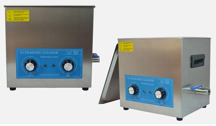
This is the manual control 10L liter heated ultrasonic circuit board cleaning machine supplied from China manufactures, it is a perfect ultrasonic cleaner for PCB circuit board cleaning. This ultrasound cleaning machine is designed with mechanical rotary swith for easily to set working time and temperature.

This kind of cleaning machine can apply to many equipment.For example,you can use to ultrasonic PCB cleaner for cleaning PCB circuit board, PC mainboard , ultrasonic carburetor cleaner for cleaning carb,engine and fuel injector.Also you can use it to ultrasonic tattoo cleaner for cleaning tattoo equipment, guns, etc.
You may want to know how about the shaver heads, razor blades, pen-heads, printer-heads, inkjet cartridges and seals, ancient coins, badges, valves, machine nozzles, electronics components?Thet are small and have a complex structure.But,please rest assured,that can not defeat it,it just like a superman,omnipotent.

New announcement

ETA and Southern Machinery provide in EMS/LED Industries ETA  and
Southern Machinery have a joint-agreement to sincerely service the customers .Our commitment to service our customers, providing them with the best solution.
ETA
and Southern machinery partnership will provide customers with feasible and
economical solutions to equip their plants with state-of-the-art assembly
equipment from China. We will provide effective and on-time after-sales support
reliably.
In
recent years, China-made PCB assembly equipment has improved on their safety and
efficiency. China is fast becoming a leader in EMS/LED-related markets. The
production in China is very competitive in good quality and low price. With
ETA s expertise in solutions, we are able to provide cost-effective solutions
with low maintenance cost.
ETA and
Southern Machinery ‘s common goal :
Listen
to  customers and be clear with customers’ requirements in Auto Insertion
and SMT market;
Recommend
customers’  the most suitable solution with the best price;
Provide
the best after-sales-service;
Adhering to the “One Belt And One Road” thought, spread
our advanced equipment and technology
to all over the world.

TDK Radial Insertion machine for PCB assembly

TDK Radials TDK is a Japanese manufacturer and supplier of both radial components and Radial insertion equipment. Unlike other Japanese companies, TDK is not vertically integrated in that they do not produce end products. In the past, they did not have dedicated Axial or DIP insertion equipment; this served as a deterrent to customers desiring to buy all their insertion mount equipment from a single source. In 1995, TDK addressed this issue by teaming up with ex-Dynapert personnel to design an Axial component inserter. This agreement produced the AC7 in 1996, followed by the ACS-2 Axial Sequencer.
Similarly, TDK’s Radial Inserter’s are not manufactured by TDK. Instead, they are manufactured by Okuma, Japan, which also produces other TDK products. Machine Design : The VC7B, VC7C, and now VC-21S machine designs incorporate a sequencer chain that delivers sequenced components to the insertion area, much the same as UIC’s Radial. The main advantage associated with a sequencer design over a shuttle design (such as Panasonic) is greater throughput speed. The component location does not effect throughput speed, and allows for replenishment of depleted components without interrupting production.
VC-21S
In late 1999 TKD introduced the VC-21S, a Radial inserter with a maximum speed of 15,000 cph. Available either as a 2.5/5.0 mm or 5.0/7.5 mm lead span machine, The VC-21S is equipped with an Auto Recovery feature. Additionally, the VC-21S operated with Windows NT. It is available in 40, 80, or 120 stations.
Although the VC-21S has been advertised, no further information is available at this time. VC7B & VC7C Horizontal Transfer There is one fundamental difference between the Radial 8 sequencer design and TDK’s design. The VC7A/B/C series transfers the components by grasping the cardboard carrier tape of the component and carrying it horizontally. During the component transfer from the chain clip to the insertion head, the component is rotated 90 degrees to a vertical position and the cardboard tape is cut from the component. The component is then ready for insertion into the PCB, but must be transferred one more time to the insertion head.
Advantages
When equipped with certain optional features, various processes can be exercised on the component while it is being transferred on the sequencer chain. Components may be electrically verified for capacitance, resistance, and inductance. Minor bends in the leads may be corrected (straightened) by a reforming unit (standard on the VC7B). Components may be rotated using the four position component rotator for insertion of polarized components but not for insertion tooling density clearance issues. However TDK’s process requires an increased number of component transfers. TDK does not offer a rotary table, which is one reason why they offer the component rotator.
Disadvantages:
1) Horizontal component transfer increases the frequency a component is handled, increasing the possibility of mishandling and mis-insertions. In contrast, the Radial 8 carries the component to the insertion area vertically by the component leads, reducing the “handling” to a single step once the component is placed in the carrier clip.
2) The VC7A/B/C series machine must slow down and therefore reduce productivity for certain component types depending on type and size.
3) The VC7A/B does not offer an auto recovery capability, while the Radial 8 features auto recovery as a standard feature.
4) Like the Radial 8, TDK can employ a soft touch pusher motion when inserting delicate components (stamped leaded parts, for example). However, unlike the Radial 8, this programmable feature slows down the machine. UIC’s soft touch pusher design is utilized for all insertions and does not effect cycle speed, but rather enhances insertion reliability for all components being inserted.
Until the release of the VC-21S in late 1999, The VC7C was TDK’s current Radial offering, a 2.5/5.0 mm lead span machine designed to insert traditional Radial components and radially taped “odd form” type components such as tact switches, potentiometers, and fuse clips. The VC7C can insert components with a maximum body diameter of up to 11mm and is available in three sequencer sizes; 40, 80, and 120 feeder stations.
Options available on TDK’s Radial machines include the four direction reverse unit, reforming (lead straightening) unit (standard on the VC7B), parts checker (verifier), component supply warning (low parts sense) unit, optical correction device (BEC), and board handling (which may include automate PCB width adjuster). Axial Equipment TDK offers also offers limited Axial insertion equipment. The AC7 single head inserter with a 16,360/hour cycle rate. They also offer a ACS-2 Axial component sequencer with up to 180 stations. TDK’s product line also includes a full line of SMC products. Distribution & Pricing Strategies TDK’s presence is global and they maintain a large installed base. Their pricing strategy is both geographic and situation specific. TDK’s prices tend to be lower and their allowable discounts tend to be higher in Asia and with multi-national accounts, than in other parts of the world.
We have seen aggressive discounting by TDK to acquire or in an attempt to retain key accounts in North America. When board handling is required, the Radial 8 with board handling allows UIC to be very price competitive with similarly configured VC7B/C. The price should be weighed against other factors such as features, capabilities and on a price/performance basis. While TDK’s machine is generally perceived as a reliable machine, when a hard failure does occur is has been difficult and time consuming to return the machine to production status. Also, there have been reports (especially in North America) of poor field service and replacement parts availability.

TDK Radial Insertion machine for PCB assembly

TDK Radials

TDK is a Japanese manufacturer and supplier of both radial components and Radial insertion equipment. Unlike other Japanese companies, TDK is not vertically integrated in that they do not produce end products. In the past, they did not have dedicated Axial or DIP insertion equipment; this served as a deterrent to customers desiring to buy all their insertion mount equipment from a single source. In 1995, TDK addressed this issue by teaming up with ex-Dynapert personnel to design an Axial component inserter. This agreement produced the AC7 in 1996, followed by the ACS-2 Axial Sequencer.

Similarly, TDK’s Radial Inserter’s are not manufactured by TDK. Instead, they are manufactured by Okuma, Japan, which also produces other TDK products.

Machine Design :

The VC7B, VC7C, and now VC-21S machine designs incorporate a sequencer chain that delivers sequenced components to the insertion area, much the same as UIC’s Radial. The main advantage associated with a sequencer design over a shuttle design (such as Panasonic) is greater throughput speed. The component location does not effect throughput speed, and allows for replenishment of depleted components without interrupting production.

VC-21S

In late 1999 TKD introduced the VC-21S, a Radial inserter with a maximum speed of 15,000 cph. Available either as a 2.5/5.0 mm or 5.0/7.5 mm lead span machine, The VC-21S is equipped with an Auto Recovery feature. Additionally, the VC-21S operated with Windows NT. It is available in 40, 80, or 120 stations.

Although the VC-21S has been advertised, no further information is available at this time.

VC7B & VC7C

Horizontal Transfer

There is one fundamental difference between the Radial 8 sequencer design and TDK’s design. The VC7A/B/C series transfers the components by grasping the cardboard carrier tape of the component and carrying it horizontally. During the component transfer from the chain clip to the insertion head, the component is rotated 90 degrees to a vertical position and the cardboard tape is cut from the component. The component is then ready for insertion into the PCB, but must be transferred one more time to the insertion head.

Advantages

When equipped with certain optional features, various processes can be exercised on the component while it is being transferred on the sequencer chain. Components may be electrically verified for capacitance, resistance, and inductance. Minor bends in the leads may be corrected (straightened) by a reforming unit (standard on the VC7B). Components may be rotated using the four position component rotator for insertion of polarized components but not for insertion tooling density clearance issues. However TDK’s process requires an increased number of component transfers. TDK does not offer a rotary table, which is one reason why they offer the component rotator.

Disadvantages:

1) Horizontal component transfer increases the frequency a component is handled, increasing the possibility of mishandling and mis-insertions. In contrast, the Radial 8 carries the component to the insertion area vertically by the component leads, reducing the “handling” to a single step once the component is placed in the carrier clip.

2) The VC7A/B/C series machine must slow down and therefore reduce productivity for certain component types depending on type and size.

3) The VC7A/B does not offer an auto recovery capability, while the Radial 8 features auto recovery as a standard feature.

4) Like the Radial 8, TDK can employ a soft touch pusher motion when inserting delicate components (stamped leaded parts, for example). However, unlike the Radial 8, this programmable feature slows down the machine. UIC’s soft touch pusher design is utilized for all insertions and does not effect cycle speed, but rather enhances insertion reliability for all components being inserted.

Until the release of the VC-21S in late 1999, The VC7C was TDK’s current Radial offering, a 2.5/5.0 mm lead span machine designed to insert traditional Radial components and radially taped “odd form” type components such as tact switches, potentiometers, and fuse clips. The VC7C can insert components with a maximum body diameter of up to 11mm and is available in three sequencer sizes; 40, 80, and 120 feeder stations.

Options available on TDK’s Radial machines include the four direction reverse unit, reforming (lead straightening) unit (standard on the VC7B), parts checker (verifier), component supply warning (low parts sense) unit, optical correction device (BEC), and board handling (which may include automate PCB width adjuster).

Axial Equipment

TDK offers also offers limited Axial insertion equipment. The AC7 single head inserter with a 16,360/hour cycle rate. They also offer a ACS-2 Axial component sequencer with up to 180 stations. TDK’s product line also includes a full line of SMC products.

Distribution & Pricing Strategies

TDK’s presence is global and they maintain a large installed base. Their pricing strategy is both geographic and situation specific. TDK’s prices tend to be lower and their allowable discounts tend to be higher in Asia and with multi-national accounts, than in other parts of the world.

We have seen aggressive discounting by TDK to acquire or in an attempt to retain key accounts in North America. When board handling is required, the Radial 8 with board handling allows UIC to be very price competitive with similarly configured VC7B/C. The price should be weighed against other factors such as features, capabilities and on a price/performance basis. While TDK’s machine is generally perceived as a reliable machine, when a hard failure does occur is has been difficult and time consuming to return the machine to production status. Also, there have been reports (especially in North America) of poor field service and replacement parts availability.

Universal Auto Insertion machine Axial Tooling History 1978-1999

Tooling History 1978-1999

Pre 1992 tooling:
Standard tooling was first introduced in 1978 and used until 1992. In the mid to late 80’s, Universal Instruments Corporation developed several versions of 5mm tooling. Changeover from standard to 5mm required complete tooled housing. Insertion reliability for 5mm was significantly lower than standard tooling.
For Footprint specifications, refer to GS-110.

1992 tooling:
Available in Standard, high density, large lead, and 5mm (improved insert reliability).
Stronger inside former than older tooling.
Easy (tooling only) changeover between standard, large lead, hi-density, 5mm.
For Footprint specifications, refer to GS-173.
For Retrofitting, see Lotus Notes Axial Retrofit Catalog data base.

1994 tooling:
Available in Standard, high density, large lead, and 5mm (improved insert reliability).
Front cam rails are lengthened (extended) for longer life, smoother operation.
Driver bodies have oil grooves.
Driver bodies are easier to install because detents don’t try to fly out.
Top surface of housings have replaceable wear plates for shear blades.
Improved dentent action prevents binding when subjected to upward pressure from clinch.
For Footprint specifications, refer to GS-374.
For Retrofitting, see Lotus Notes Axial Retrofit Catalog data base.

1996 5 & 5.5mm tooling for Dual Head and VCD/Sequencer:
Not Available in Standard version.
Most tooling pieces increased life 300 to 400 percent.
Outside formers are slightly larger for more strength (footprint .090 x .090).
Outside formers have carbide for longer life.
Outside formers have a bigger bottom V to handle bent components better.
Outside former vertical groove is a true V to provide two lead contact surfaces for more secure lead holding capability.
Kickout arms and driver body cam surfaces have been redesigned for smoother operation.
Inside former and shear blocks are longer to work with the kickout/driver body changes.
New sequence tape guides feed bent components into head better than dual head VCD.
For Footprint specifications, refer to GS-367, except for outside former footprint. The GS has an incorrect footprint dimension.
For Retrofitting, see Lotus Notes Axial Retrofit Catalog data base.

1998 Standard Tooling Available for VCD/Sequencer Only:
Outside formers are slightly larger for more strength.
Outside formers have carbide for longer life.
Outside formers have a bigger bottom V to handle bent components better.
For Retrofitting, see Lotus Notes Axial Retrofit Catalog data base.
Outside former vertical groove is a true V to provide two lead contact surfaces for more secure lead holding capability.
Kickout arms and driver body cam surfaces have been redesigned for smoother operation.
Inside former and shear blocks are longer to work with the kickout/driver body changes.
For Footprint specifications, refer to GS-367, except for outside former footprint. The GS has an incorrect footprint dimension.
For Retrofitting, see Lotus Notes Axial Retrofit Catalog data base.

Series 8 high speed tooling (1999)
Designed for the higher insertions speeds of the VCD 8 series machines.
Same long life characteristics as the carbide 1996 5mm and 1998 standard tooling.
For Footprint specifications refer to GS-374.

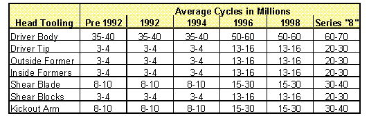
Estimated Tooling Life* History

* Tooling life is highly dependent upon a number of factors. These factors include:
Lead composition variance
Lead diameter variance
Tooling maintenance
Working environment (dust, humidity, temperature, etc.)

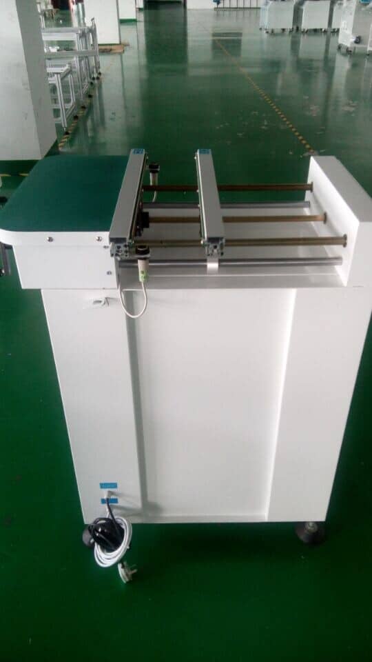
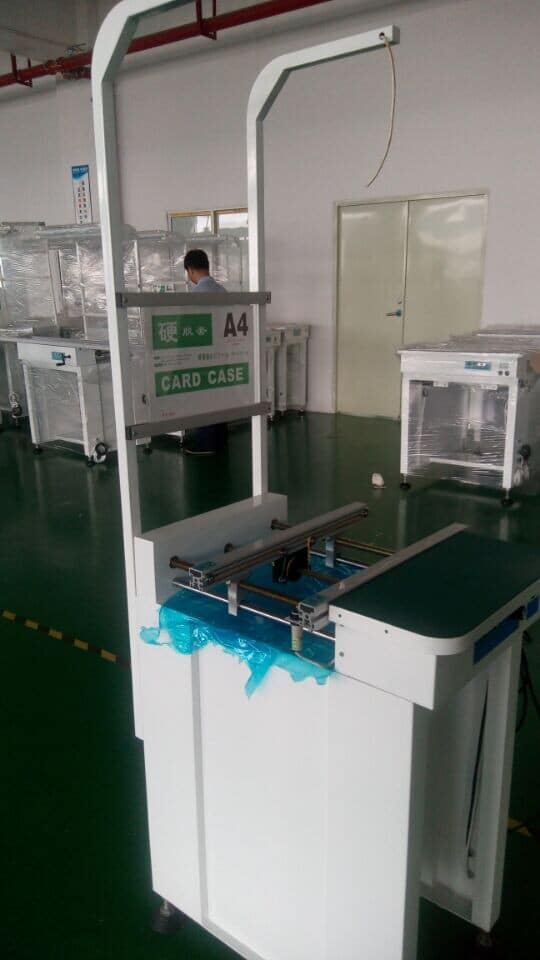
SMT line solution PCB Board Flow Conveyor Checklist

Customer  ____________________________________        Date  _____________________________

Old Serial Tag #  _______________________________        Equip #  __________________________

Prod Code  _____________ Description  __________________________________________

Qty  _______   RMD Identifier #  _______   Ord #  _____________   Prod Order #  _______________

Builder Name/Initial  ________________________________________           Clock #  __________

QA Technician Name/Initial  __________________________________           Clock #  __________

Shipping Clerk Name/Initial  __________________________________           Clock #  __________

1. Turn For Final Inspection Builder/QA Tech

A. Leveling legs are correct type (standard pass thru ______________

height or special).

B. Conveyor speed verified mode functions and board ______________

sensors set and operational.

C. Parallelism of rails set. ______________

D. Input voltage correct to order requirement. ______________

E. Conveyor length correct to order requirement. ______________

F. Board flow direction is to order requirement. ______________

2. Visual Inspection Builder/QA Tech

A. Check for dents, scratches and poor painting. ______________

B. Check for loose hardware.  ______________

C. Interfacing hardware including. ______________

D. Covers installed. ______________

E. Cables installed or packed in carton. ______________

3. Pre-Shipment Builder/Ship Clerk

A. Run Delivery Note. ______________

Builder/Ship Clerk

B. Verify all items on order are present. ______________

C. Properly package all items in carton(s) and/or power ______________

pack(s).

D. Fill out box content sheet. ______________

E. Label carton(s\) and/or power pack. ______________

F. Notify shipping clerk. ______________

4. Close Out Procedure Builder/Shp Clerk

A. Review Delivery Note with shipping clerk. ______________

B. Turn machine over to shipping clerk. ______________


AI spare parts、Universal Parts,UIC,TDK.VCD Sequencer.SMT,THT,PCB,PCBA,AI,wave soldering,reflow oven,nozzle,feeder,wave soldering,PCB Assembly, LED, LED lamp, LED display,FUJI,SMT,Cp,XP,NXT,AIM,IP,DEK,Stencil,Screen printer,TDK,Siemens,Siplace SMT conveyor 1 (3) AI spare parts、Universal Parts,UIC,TDK.VCD Sequencer.SMT,THT,PCB,PCBA,AI,wave soldering,reflow oven,nozzle,feeder,wave soldering,PCB Assembly, LED, LED lamp, LED display,FUJI,SMT,Cp,XP,NXT,AIM,IP,DEK,Stencil,Screen printer,TDK,Siemens,Siplace AI spare parts、Universal Parts,UIC,TDK.VCD Sequencer.SMT,THT,PCB,PCBA,AI,wave soldering,reflow oven,nozzle,feeder,wave soldering,PCB Assembly, LED, LED lamp, LED display,FUJI,SMT,Cp,XP,NXT,AIM,IP,DEK,Stencil,Screen printer,TDK,Siemens,Siplace AI spare parts、Universal Parts,UIC,TDK.VCD Sequencer.SMT,THT,PCB,PCBA,AI,wave soldering,reflow oven,nozzle,feeder,wave soldering,PCB Assembly, LED, LED lamp, LED display,FUJI,SMT,Cp,XP,NXT,AIM,IP,DEK,Stencil,Screen printer,TDK,Siemens,Siplace AI spare parts、Universal Parts,UIC,TDK.VCD Sequencer.SMT,THT,PCB,PCBA,AI,wave soldering,reflow oven,nozzle,feeder,wave soldering,PCB Assembly, LED, LED lamp, LED display,FUJI,SMT,Cp,XP,NXT,AIM,IP,DEK,Stencil,Screen printer,TDK,Siemens,Siplace AI spare parts、Universal Parts,UIC,TDK.VCD Sequencer.SMT,THT,PCB,PCBA,AI,wave soldering,reflow oven,nozzle,feeder,wave soldering,PCB Assembly, LED, LED lamp, LED display,FUJI,SMT,Cp,XP,NXT,AIM,IP,DEK,Stencil,Screen printer,TDK,Siemens,Siplace

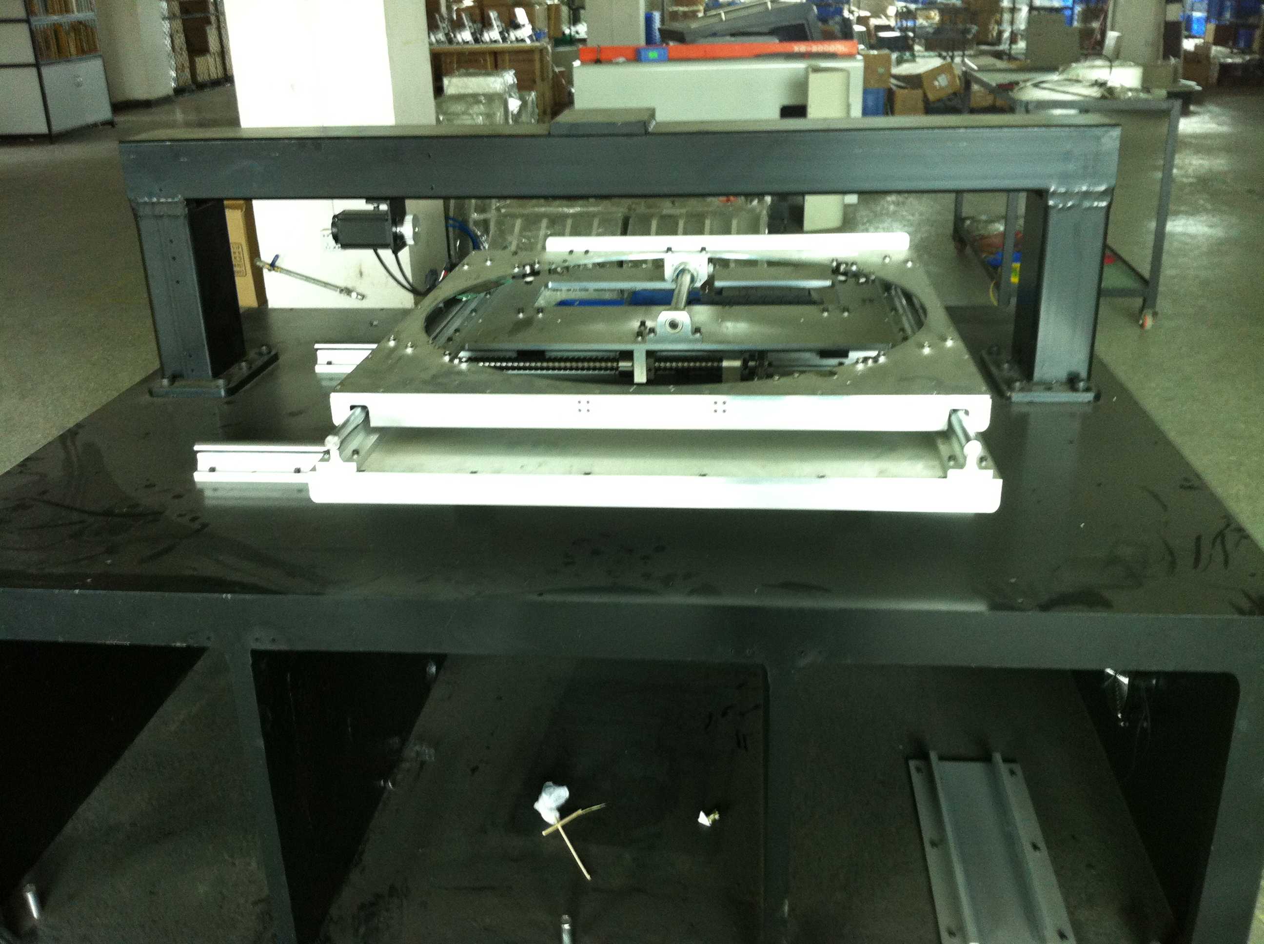
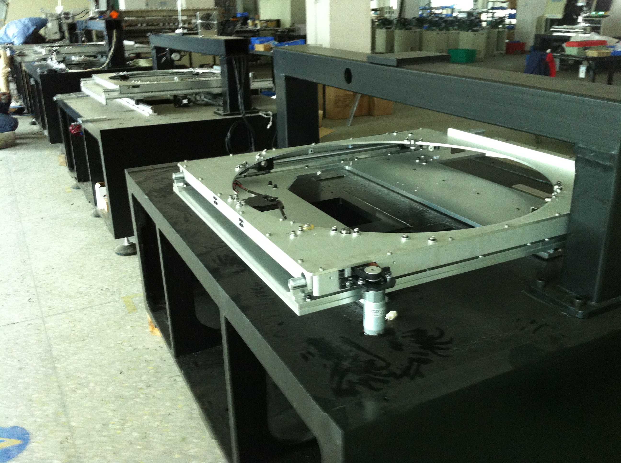
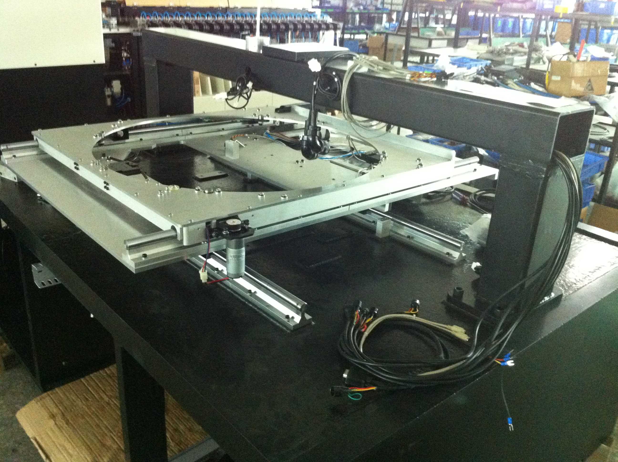
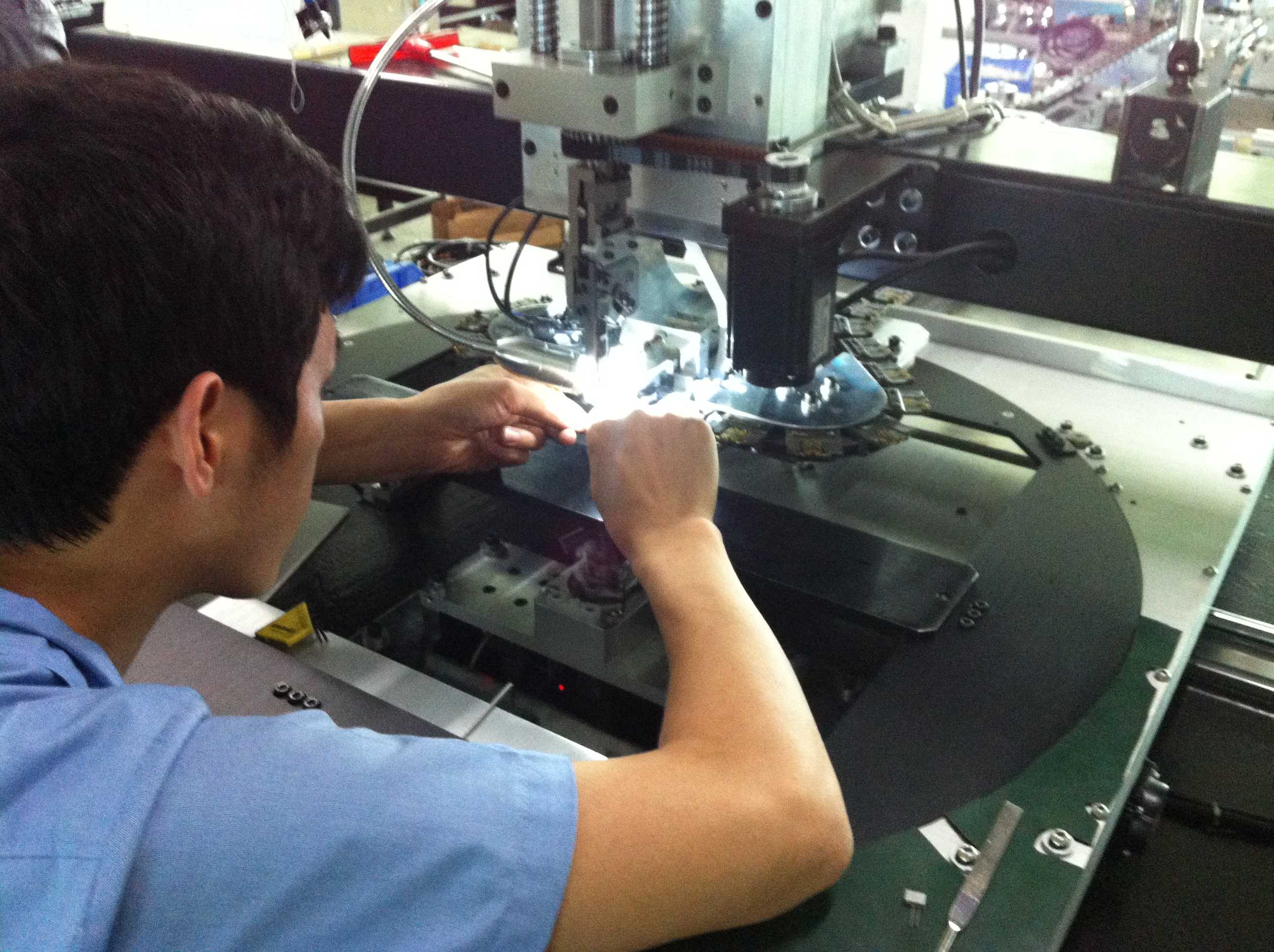
Radial Auto Insertion machine POSITIONING SYSTEM Check list

STEP & DESCRIPTION

Builder

Check base casting build.

Thompson shaft oriented torqued and lubed with 10w oil.       

Leveling pads mounted but not tightened.

Foam insulation in place.        

Check y & x frame build.         

Bearings & retainers mounted

Verify the x & y bearing preloads are set.    

Limit rails and limit blocks mounted and activate limit switches.

Tie clamps mounted.               

All brass pneumatics fittings installed.                        

Insure base, y frame, and x frame are mated together. 

Check build & installation of x & y paddles.

Hardware tight dowels in place.  

Bearings installed.               

Check x & y table movement.

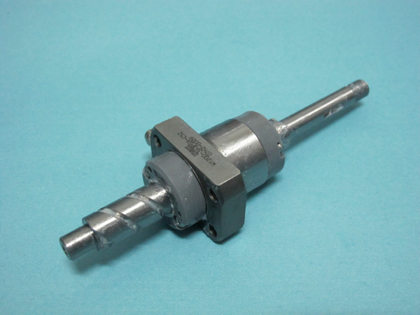
Ball screw units installed and lubed.  

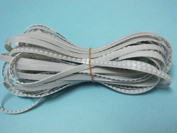
Motor, drive belt installed with proper belt tension adjusted.

Rotary disc installed.

Wheels mounted with proper hardware and internal tooth CSK.

Lock assy & drive motor installed & adjusted.       

Wheel cams adjusted so dowel pins fit through disc bushings into the x-frame bushings. 

Safety covers in place.          

Insure the positioning system cable harness is installed.

Insure limit actuators activate the limit switches.

Positioning system installed on lower console.

use loctite 271 and torque to 60 ft/lbs.) Adjust and lock down leveling pads

Insure that base frame leveling pads are seated against the console frame and locknuts tight.

AI spare parts、Universal Parts,UIC,TDK.VCD Sequencer.SMT,THT,PCB,PCBA,AI,wave soldering,reflow oven,nozzle,feeder,wave soldering,PCB Assembly, LED, LED lamp, LED display,FUJI,SMT,Cp,XP,NXT,AIM,IP,DEK,Stencil,Screen printer,TDK
POSITIONING SYSTEM – Table

AI spare parts、Universal Parts,UIC,TDK.VCD Sequencer.SMT,THT,PCB,PCBA,AI,wave soldering,reflow oven,nozzle,feeder,wave soldering,PCB Assembly, LED, LED lamp, LED display,FUJI,SMT,Cp,XP,NXT,AIM,IP,DEK,Stencil,Screen printer,TDK
POSITIONING SYSTEM – Table

AI spare parts、Universal Parts,UIC,TDK.VCD Sequencer.SMT,THT,PCB,PCBA,AI,wave soldering,reflow oven,nozzle,feeder,wave soldering,PCB Assembly, LED, LED lamp, LED display,FUJI,SMT,Cp,XP,NXT,AIM,IP,DEK,Stencil,Screen printer,TDK
POSITIONING SYSTEM – Table

AI spare parts、Universal Parts,UIC,TDK.VCD Sequencer.SMT,THT,PCB,PCBA,AI,wave soldering,reflow oven,nozzle,feeder,wave soldering,PCB Assembly, LED, LED lamp, LED display,FUJI,SMT,Cp,XP,NXT,AIM,IP,DEK,Stencil,Screen printer,TDK
POSITIONING SYSTEM – Table

AI spare parts、Universal Parts,UIC,TDK.VCD Sequencer.SMT,THT,PCB,PCBA,AI,wave soldering,reflow oven,nozzle,feeder,wave soldering,PCB Assembly, LED, LED lamp, LED display,FUJI,SMT,Cp,XP,NXT,AIM,IP,DEK,Stencil,Screen printer,TDK
POSITIONING SYSTEM – Table
AI spare parts、Universal Parts,UIC,TDK.VCD Sequencer.SMT,THT,PCB,PCBA,AI,wave soldering,reflow oven,nozzle,feeder,wave soldering,PCB Assembly, LED, LED lamp, LED display,FUJI,SMT,Cp,XP,NXT,AIM,IP,DEK,Stencil,Screen printer,TDK