Features & Benefits of Universal’s Axial Insertion machine — VCD/Sequencer 8

Feature

Benefit

High performance Positive Axis Control servo-drive system

Dynamic motion control for smoother,  faster,  more precise motion, yielding precise component insertion and clinching with less mechanical wear and noise.  PAC provides very high repeatability.

Insertion Head

The insertion head is direct servo-driven, with a robust and highly reliable rack-and-pinion drive. 

The rack and pinion coupled with the direct drive provide long life and precise positional accuracy, resulting in high cycle rates, greater insertion process control, and lower PPM, with less noise and wear.

Minimized manual set-ups and adjustments

Elimination of manual set-ups reduces downtime.  To ensure consistency, set-ups are now performed through IM UPS Diagnostics software.  

Insertion Tooling

Newly designed tooling has a significantly longer life –up to five times longer than the previous model.

Tooling has to be replaced less often, reducing down time, tooling inventory and cost.

Tooling uses carbide inserts and titanium nitride coating.

This extends the tooling life.

The new design better handles bent input component leads.

The robust design reduces machine interruptions & down time caused by bent input component leads.

Four tooling options are available:

5mm: insertion spans from 5mm (0.197”) to 21.59mm 

( 0.85”)

5.5mm: insertion spans from 5.5mm(0.217”) to 24.13mm (0.95”)

Standard: Insertion spans from 7.62mm (0.3”) to 24.13mm (0.95”)

Large Lead: insertion spans from 7.62mm (0.3”) to 23.88mm (0.94”)

These options satisfy most applications.  If you are unsure which tooling to choose, contact the Product Team

Centering System

New cam-actuated component centering system is driven by the insertion head motor

The new design significantly increases reliability.

The centering door has been eliminated.

Better visibility and accessibility to the insertion area.

Adjustments have been reduced by 50%.

Only five simple adjustments are required on the centering system, reducing maintenance time.

The new centering system is a simple design, with 50% part reduction over the previous model.

The design provides increased reliability and extended life, with significantly less maintenance.

The centering fingers have replaceable carbide inserts

The inserts keep costs down and reduce maintenance cost and time. 

Servo-Driven Cut and Clinch

The clinch is operated with a servo-driven rocker/slide mechanism.

This mechanism provides quiet and repeatable up/down operation, increasing reliability and reducing maintenance.

The servo-driven anvil mechanism operates in a two-step motion.  The lower position is used for table rotation and board transfer, while the mid-position to full up-position is used for cutting and clinching component leads.  

The two step motion reduces motion cycle time and increases operating life.

Right and left anvils are coupled.

The coupled anvils assure synchronous operation and simplify set-ups. 

Anvil height set-up is performed via IM diagnostics software.

Guesswork is eliminated.  The anvil height is consistently set to program dimensions through the software, for greater accuracy and precision.

All mechanical adjustments are in the front and on the top of the clinch base.

The adjustments are in easy-to-reach locations, making them quicker and easier to perform.

The clinch assembly is pinned to the frame.

Head alignment after clinch removal and replacement is eliminated.

The clinch cutters use the proven Universal pneumatic actuators.

The actuators assure a full range of operation on leads from 0.38mm (0.015”) to 0.81mm (0.032”).

Positioning System

The positioning system operates by new X-Y motors with tachometer feedback and more responsive servo amplifiers.

7.62mm (0.30”) table moves are possible with no effect on machine cycle rate.

The table motion is smoother and more controlled.

Improved table motion increases the life of mechanical parts.

Insertion Span Axis

The insertion span axis uses a direct drive system with a brushless DC servo motor.

This drive eliminates belts, external motors, and limit switches, for greater reliability and less maintenance, while providing more precise positioning.

Chain-to-Chain Transfer

The new scrap remover is mechanical.

The design is a passive mechanical device that is quiet, clean and reliable.

The sequencer chain drive is operated by a new brushless servo motor.

The drive gives more precise dynamic position control for improved component transfer, lowering PPM.

Board Error Correction (BEC) and “Teach”

BEC is a four quadrant electro-optical sensor, used to measure expected programmed PCB hole locations.  It provides feedback to the control processor to compensate for PCB hole misalignment, which drives the X-Y table to the desired hole location.

BEC adjusts a given pattern to a given board, significantly lowering PPM.  BEC compensate for circuit board construction variations between tooling holes and related patterns, improving insertion reliability.

“Teach”uses BEC to custom fit a pattern to a board.

“Teach”greatly improves pattern accuracy and lowers PPM. 

Add – On Sequencer Modules

The sequencer is available with up to 220 stations (in 20-station add-on modules).

The add-on modules provide flexibility in meeting a variety of applications.

Improved “Low Part’warning is displayed on the machine monitor, which indicates the module and level of the “low part”condition.

“Low Part”warning is more visible to the operator, defining the location better.  The warning is recorded, for better process control.

The dispense head guides and bearings are newly designed.

The new design improves reliability and ease of use.

The pneumatic valves are DC.

DC valve provide improved response for more consistent dispense head actuation.

Refire

Optical refire senses missing parts in the component input tape.

Refire reduces “Part Missing”errors by actuating the dispense head if a part is not sensed in the component input tape.

Easy-to-see LEDs show dispense head refire status.

The LED’s simplify input component loading by visibly displaying refire status and input component sensing in the dispense head.

Refire information is fed back to the machine controller

The feedback provides better information for machine performance analysis.

Jumper Wire Dispense System

Up to two jumper wire dispensers may be used in the machine.  Jumper wire dispensers may be placed on stations 3 and 23.   

Even the most “jumper wire intense”applications can be satisfied with no effect to machine cycle speed.

Jumper wire dispenser design improvements:

Improved wire feeder alignment

New drive bearing

The new design gives better cut length accuracy and increased wire dispense reliability, longer bearing life.

System Software

The VCD/Sequencer 8 utilizes IM-Universal Platform Software (IM-UPS)

This is the same Windows-based software used in Universal’s other through hole Series 8 machines and surface mount equipment, reducing the learning curve for operation, maintenance, and programming.

Graphical user interface with “pop-up”error screens

Easy to understand and use, especially for non-English speakers.

Advanced Product Editor (APE) offers a component library, graphical display of PC board, and insertion path.

APE makes programming quick, accurate, and easy.

Optimization feature

Optimization improves programs by ordering steps in the fastest insertion path.

Management data is generated & stored in a database

Machine performance can be tracked and graphed to provide a quick aid for decision making and reporting. 

Machine event messages are displayed and logged.

Machine activity can be traced, greatly aiding analysis.

Diagnostics are provided on-line

The diagnostics through software provide point-and-click simplicity for set-up and sub-system troubleshooting.

On-line manuals and user help is provided

Eliminates the need to keep manuals near the machine

Product trainer

Available in English, Spanish, and Chinese, Product Trainer provides operating and maintenance instructions through a CD.  This tool increases workforce competency and productivity  

Repair

The operator clears any misinserted component, and places a new component in the repair location.  If the ERV option is present, the machine verifies the correct part, inserts it, and clinches it automatically.

The “repair”mode enables outgoing board quality to reach 0 PPM.

Expanded Range Verifier (ERV) –Option

ERV provides on-line verification of component values and polarity.

ERV reduces the possibility of inserting defective, out-of-sequence, or incorrectly oriented components in the pattern location.

Other Features

Uninterruptable Power Supply

In the event of a blackout or brown out, the UPS provides up to 10 minutes of power.  This allows the operator to save patterns and end the current cycle.

Audible alarm

The audible alarm is programmable to alert operators of machine conditions. 

How to evaluate SMT Auto Insertion machine supplier

Quality System Assessment Summary Report

Supplier:  

Commodity Team:

Primary Audit Contact:

Address:     


Supplier Commodity/Product Specialty:

Audit Team:


Phone: 


Fax: 


Elements


Max.

Audit Date:

Re-audit Date:

/ /

%

Improvement


Physical/ Logistical

Capabilities

(for information only)

Score

(0-3)


Score

Score

Score


A. Geographic location

3

1 Management Responsibility


B. Plant condition / size

3

2 Quality System


C. Employment / labor recruiting

2

3 Contract Review


D. Finance resources

3

4 Design Control


E. Pricing history

2

5 Document and Data Control


F.   Equip. Condition /age / application


2

6      Purchasing and verification


G. Backlog / capacity status

2

7 Customer Supplied Products


Yes/ No for following

8 Product Identification and Traceability

4


H. ISO / QS 9000 certified

Yes

9 Process Control


I. Design Capability

Yes

10 Inspection and Testing


J. Quick turn/prototype capability

Yes

11    Control of Inspection and Test Equip.


12


K. JIT capability / Kanban

Yes

12 Inspection and Test Status

2


13 Control of Nonconforming Product


14 Corrective and Preventive Action

6


Calculations:

15 Handling, Storage, Pack. and Delivery

9


1. Quality System Score (%):

16 Control of Quality Records

5


Total Audit Score x 100

17 Internal Auditing

10


(Total Max. Score – N/A Score)

18 Training

6


2. % Improvement:

19 Servicing

4


(New Score – Previous Score) x 100

20 Statistical Techniques

30


Previous Score

21 Continuous Improvements


Total Score


Auditor’s Signature:   


% Score


Date: 

Quality Control for Auto Insertion machine manufacturing


Quality Control


Every Auto Insertionl machine
is subjected to a Quality Acceptance Test (QAT) before being shipped to
its customer. There are 4 phases to a QAT:


Phase I – Pre-Dry Cycle


The
appropriate pattern program is loaded and the machine performs a short
part run with all motions and mechanisms functioning to check setups and
speed. All data is recorded on the machine’s event log.


Phase II – Dry Cycle


Can
only occur after successful completion of the Pre-Dry Cycle. The
machine is run with all motions and mechanisms functioning but without
boards or inserting components for a pre-specified period of time. All
data is recorded on the machine’s event log.


Phase III – Integrity Run (Final Run)


Can
only occur after successful completion of the Dry Cycle. This is a
simulated production run to check insertion performance and speed.
Results are recorded on the machine’s event log.


Axial Inserter

S4000

Radial Inserter

S3000

Phase I


Parts Run

2000

2000

Insertion PPM *

0

0

Intrinsic Availability **

100%

100%

Phase II


Length of Run

12 hrs.

12 hrs.

Intrinsic Availability

95%

95%

Phase III


Minimum Parts Run

20000

20000

Allowable Insert Errors

10

20

Intrinsic Availability

95%

95%

Acceptable PPM Levels

500 – 1000

1000

Confidence Level

95%

95%


* (# of good insertions / total # of insertions)

** (# of hours the machine is ready to run / total # of hours machine planned to run)


Phase IV – Customer Acceptance (Optional)


Can
only occur after successful completion of the Integrity Run. The
customer visits the factory to watch verify the machine’s ability to
meet performance requirements. The customer’s production run is
simulated and all options are verified and explained. 


 For any further questions regarding the customer acceptance procedure, please  contact:


 Albert Wen

 Albert@smthelp.net


Phase V – Preproduction Acceptance (At customer site)


Service engineer installs the machine and assures it is setup
and running with the same degree of operational efficiency as at the
factory.


SMT machines Cpk Conversion to Defects over Time at Typical Run Rates

When defect rates are higher than what the machine’s Cpk would indicate 

according to this table, it is due to one of several things: machine set-up or 

maintenance issues, process issues, component imperfections,  etc.

SMT,THT,PCB,PCBA,AI,wave soldering,reflow oven,nozzle,feeder,wave soldering,PCB Assembly, LED, LED lamp, LED display,

Axial Insertion machine Competitive Analysis – Amistar AI-6448 vs Universal 6241D

This paper compares Amistar’s Model AI-6448 Inserter/Sequencer and Universal’s Model 6241D VCD/Sequencer machines.  

Amistar Corporation, head quartered in San Marcos, California, is a small company – 154 employees and ~ $20 mil in annual sales.  Both resources and exposure are limited and Amistar predominantly sells via representatives.  To my knowledge, manufacture of the Amistar Model AI-6448 was discontinued approximately 7 years ago.  Because of this, current information about Amistar is limited.

Amistar advertises the AI-6448 on their web page as follows:

The Amistar AI-6448 is a fully automated Axial component inserter. 

Stand alone automation: sequences & inserts in one operation 

Cycle rate of 9,600 insertions per hour 

Capacity: 64 cartridges, 88 reels 

Automatic optical position correcting via PCS (Position Correcting Servo) 

Axial component verifier 

Lead protrusion inspection 

Microprocessor control 

Easy to program 

Easy to use

Amistar’s approach to axial insertion with their model AI-6448 is very different from Universal’s.  Axial lead components are cut at the dispensing head and dispensed down a tube via free fall (gravity) compressed air. The component is then recaptured at the transfer station for eventual insertion into the PCB.  The Amistar machine has capacity for 88 reels and 64 cartridges, but no ammo pack capability.  Each cartridge is kitted off line and capable of handling a maximum of 75 components.  Some customers believe this feature works well for small production runs, although it does add another preparation step to the process, as well as additional component handling, which increases the potential for component damage and or errors.

Other differences from the method in which Universal handles axial components include the way in which components are centered.  Amistar centers on lead end instead of the component body.  This can lead to components being cut off-center and consequently effect insertion reliability.  

In order to utilize the AI-6448’s method of transferring components to the insertion area, the positioning system is very low to the floor making it difficult to maintain and/or access.  Universal FE’s have had the opportunity to evaluate AI-6448’s installed at customer locations and have reported concerns with the durability, accuracy and repeatability of the rotary table.  

While the Amistar Model AI-6448 can be equipped with board handling, the method utilized is limited to stand-alone applications, not allowing for pass-through or in-line capability and takes up a lot of floor space.  

In the past, Amistar has sold the AI-6448 when the prospective customer is interested in combined sequencing and insertion and price is a major factor.  Typically, the price of the AI-6448 is much less than the 6241 in a similar configuration (similar in a sense that there are similar number of inputs).  When speed, capability and machine performance are added to the equation, the AI-6448 is not as attractively priced.  Because Amistar has not manufactured the AI-6448 in 7 years, no current pricing information is available to us.

Feature

Amistar Model AI-6448

Axial Insertion Machine

Universal Model 6241D

VCD Sequencer/Inserter

Speed

9,600 cph

16,000 cph

Max PCB Size w/Board Handling

20″ x 20″

(508mm x 508mm)

19″ x 16″ 

(483mm x 406mm)

Max PCB Size w/out Board Handling

20″ x 20″

(508mm x 508mm)

18″ x 22″ 

(457mm x 559mm)

Max # of Inputs

52mm only:  64 cartridges, 88 reels 26mm not available

ammo pack not available

52mm: 220 stations in 20 station increments

26mm: 220 stations in 20 station increments

Reel and/or Ammo Pack

Insertion Span

Std:.300″ – .800″ 7.62mm – 20.3mm)

5mm:  Not available

Std: .300″ – .950″ (7.6mm – 24.1mm)

5mm: .197″ – .850″ (5mm – 21.6mm)

Component Centering

Component Leads

Component Body

Board Error Correction

Yes

Yes

Verification

Yes  – limited capability

Yes

Lead Sensing

Yes

Yes – dual lead

Rotary Table

Yes

Yes

On-Line Programming

Yes

Yes

Automatic Board Handling

Yes

Yes – designed and manufactured by Universal

Part Transfer

Chute

Sequencer

Refire

Yes

Yes

Part Repair

Automatic

Semi-automatic

Max Body Length

.400″(10.2mm)

.620″(15.7mm)

Max Body Diameter

.175″(4.5mm)

.420″(10.69mm) – 2 x PCB thickness

Lead Diameter

Standard Tooling: 

copper lead

.015″- .036″(.38mm – .9mm)

.015″- .032″(.38mm – .81mm)

Standard Tooling: 

copper lead

.015″- .026″(.38mm – .66mm)

.015″- .032″(.38mm – .81mm)

5mm Tooling: copper lead

Not available

.015″- .032″(.38mm – .81mm)

5mm Tooling: copper lead

Not available

.015″- .032″(.38mm – .81mm)

Jumper Wire Capability

Yes

Yes

Low Part Sensing

No

Yes

Universal’s 6241D is still manufactured and design development activities continue to enhance and improve the machine as part of Universal’s ongoing commitment to the through-

hole market.  In addition to the items listed above, recent enhancements in the Model 6241D product line include:

Axial Tech Advisor is available which provides Operators and Maintenance Technicians on-line, menu-driven diagnostic information and assistance on machine operation, troubleshooting, maintenance and repair at the time of need.  It is available in English, Chinese and Spanish.

Newly designed jumper wire dispensing system provides fast, reliable and accurate wire feed and accommodates .45mm to .6mm wire diameters

Newly designed dispensing heads are easy to operate, greatly extend life of wearable parts and allow for quick changeover with minimal scrap.

The 6241D now offers a low-level Sequencer Add-On Module for easy reach loading.  It features low part sensing to alert the operator before parts are depleted, allowing replenishment without interrupting machine operation, removable end scrap bins for easy clean out, and refire is offered on each dispensing head.

Precision WBH’s, both adjustable and fixed are available.  Universal can also accommodate Amistar WBH’s.   

The 6241D contains a 4 color light tower which signals machine operating status.

New and improved board handling increases system reliability, ease of PCB changeover and ease of assembly. (See SH BHS Improvements Presentation).

Newly designed 5mm tooling is now available for increased reliability, longer life and better handling of bent lead component input.  (See 5mm Tooling Improvements Presentation).  Customers have told us this tooling lasts three times longer than the old style tooling

Universal offers a AAA version of the VCD Sequencer machine that is capable of inserting 26mm input.

The 6241D is CE marked to meet all European health and safety standards.

While Universal does not offer conversion software for converting Amistar pattern programs, the Amistar programs could be treated as CAD data and translated via the CAD translator available in PPU.  If your prospective customer would like to supply us with one of their programs and briefly explain the fields, we will review the program and offer suggestions for performing the translation.

And last, but not least, Universal offers a support infrastructure which includes a knowledgeable and experienced Field Service organization, world wide Training Centers and Parts Distribution Centers as well as an extensive installed base.     

Auto Insertion machine Tooling Design vs. Range of Inserted Component Wire

1.0 INTRODUCTION

Do you have customers who are willing to simplify the Axial automated insertion process, speed up machines, lower preventative maintenance (pm) downtime and ppm levels and generally reduce manufacturing costs?  If so, then this paper may interest you.

Universal Instruments Corporation is currently working to customize tooling for customers who have evolved their manufacturing processes to two and three step processes for Axial insertions, thereby dedicating machines to run a limited range of components.  In step one for example, a machine inserts only 5mm insert spans and then in step 2, a second machine inserts various wire diameters.  This is a radical change from the current manufacturing philosophy of fully populating a board in one pass through a machine.  However, history has shown that by limiting the range of wire diameters inserted and then designing tooling to specifically handle that range, the manufacturing process becomes more controlled, insertion performance improves, pm downtime and ppm levels decrease and ultimately, manufacturing costs decrease.

Admittedly, this approach is not viable for every customer.  Universal offers a variety of tooling configurations that if used according to specification, will provide excellent insertion performance.  A customer may have no need to run a wide range of wire diameters or they may want to revisit their manufacturing process to make improvements.  For those customers, Universal offers customized tooling for dedicated applications.  Customized tooling will handle a limited range of wire diameters to optimize insertion performance and maximize tooling life.

This paper discusses the relationship between tooling design and  wire diameter range of inserted components with the goal of creating an awareness and understanding of this relationship and it’s significance.

2.0 FACTORS AFFECTING THIS RELATIONSHIP

2.1 Depth of V-Groove of Outside Former

One important factor affecting the relationship of tooling design and range of insertable wire diameters is the depth of the V-groove of the Outside Former.  Our current specifications for Axial tooling are as follows:

Standard

High Density

Large Lead

5mm

26mm AAA

Bottom View of Outside Former


Wire Diameter Range / Material

Steel:

.015”-.032”

(.39) – (.82)

Copper:

.015”-.032”

(.39) – (.82)

Steel:

.015”-.025”

(.39) – (.64)

Copper:

.015”-.032”

(.39) – .82)

Steel:

.025”-.032”

(.64) – (.82)

Copper:

.025”-.042”

(.64) – (1.01)

Steel:

.015”-.025”

(.39) – (.64)

Copper:

.015”-.028”

(.39) – (.72)

Steel:

.015”-.020”

(.39) – (.51)

Copper:

.015”-.024”(.39) – (.61)

Driver Tip Width

.030”

(.77)

.030”

(.77)

.050”

(1.27)

.017”*

(.44)

.012”*

(.31)

Metric equivalents are bracketed

* Not entire width but dimension from edge of Driver Tip to side of Outside Former

When the wire diameter is smaller than the depth of the V-groove of the Outside Former, the lead has excess space and moves within the V-groove.  This uncontrolled condition leads to a ‘weak’form. 


 V-groove with Small Lead Diameter

When the wire diameter is larger than the depth of the V-groove of the Outside Former, the yieldable Inside Former flexes to make room for the bigger lead.  Continual flexing causes the O-rings to wear out which leads to a ‘sloppy’Inside Former and ‘weak’forms.  Outside Formers have been known to split at the V-groove from continual stress.  Long term, continual flexing will damage the Tooling Housing by loosening it and making it ‘sloppy’.  


 V-groove with Large Lead Diameter

The optimal condition is wire diameter equal to the depth of the V-groove of the Outside Former.  In this condition, the lead is large enough so that is does not ‘move’within the V-groove, and yet it does not continually flex the Inside Former.


 V-groove with Optimal Lead Diameter

When Standard tooling is compared to 5mm tooling, it becomes clear why 5mm tooling is less reliable when inserting components with large lead diameters than Standard tooling.  

TOOLING

DEPTH OF V-GROOVE

WIRE DIAMETER RANGE

Standard

.028”(0.71mm)

.015”-.032”(0.39mm – 0.82mm).

5mm

.018”(0.46mm)

.015”- .028”(0.39mm – 0.72mm)

The depth of the V-grooves vary by .010”(0.26mm) and yet the range of wire diameter is very similar.

2.2 Radius of V-Groove of Outside Former

Another factor is the radius of the V-groove of the Outside Former.  The V-groove is actually a radius of .016”(0.41mm) for all tooling types except large lead tooling which is .019”(0.49mm).  Because this is a radius, not a diameter, the optimum lead size for this size radius is .032”(0.82mm)  This radius creates a situation that allows a small wire diameter to ‘roll around’or be uncontrolled in the groove.  A true V-groove improves this condition by creating a 2 point contact.  


One Point Contact

Two Point Contact


2.3 Body Length to Insertion Length

Body length to insertion length is another critical issue in this discussion.  The bigger the gap between the component body and the bend of the lead, the more room there is for the insertion tooling.  As the Driver Tip descends, it can damage a component body that is too long for the specified insertion span.  Clearance is also needed for the Inside Former coming beneath the bend of the lead.  A bend too close to the component body can also cause damage.  Maximum body length is obtained with the following formula: 

Programmed Z-Span = Insertion Span + 1 Lead Diameter

Maximum Body Length (clearance between Driver Tips)

= Insertion Span + 1 Lead Diameter – 2 x Depth of Outside Former V-groove – 2 x Driver Tip Thickness 

Do not use components with body lengths at the maximum length.  Allow .020”(0.51mm) on each side of a component body for clearance and to account for tolerances.


Component Body Leaving

Clearance

Component Body Leaving

No Clearance


2.4 Driver Tip Position

During a component insertion, the Driver Tip rests on the horizontal surface of the lead.  When a lead has a ‘weak’form, the Driver Tip rests on top of the bent portion of the lead.  As the Driver Tip tries to push a component through the holes of the pc board, it has a tendency to ‘slide off’a lead, leading to a standup or failed insertion.  This is true of 5mm tooling because of its small Driver Tip.


Driver Tip Position

during insertion

Driver Tip position during insertion 

of weak form lead


3.0 SUMMARY OF ABOVE CONDITIONS

· Wire diameters significantly smaller than the depth of the V-groove of the Outside Former are uncontrolled within the V-groove.  This is caused by one point contact and excess space, which leads to a ‘weak’form and poorly controlled insertion.  Small lead components without a ‘crisp’form are also at risk of misinserting because the Driver Tip may ‘slip off’the lead, while pushing it through the pc board.  This condition is seen most often with 5mm tooling.

· Wire diameters significantly larger than the depth of the V-groove of the Outside Former continually flex the yieldable, Inside Formers causing premature tooling wear-out of the Inside and Outside Formers as well as other parts of the tooling.

· Acceptable component body length varies with Z-span, but clearance is required for the Inside Formers and Driver Tips during insertion so the component body is not damaged. 

4.0 OPTIMAL CONDITIONS

To optimize insertion performance and maximize tooling life, it is best to limit the range of wire diameters inserted with any tooling selection, keeping in mind the optimal wire diameter is the same size as the V-groove of the Outside Former.  For example, if the wire diameter range of a particular application is .018”- .022”, a .020”V-groove is optimal.  This eliminates the problems mentioned above and allows optimal tooling life, process control and low insertion ppm.  

Making use of the squeeze function when writing pattern programs can also help.  If a component lead diameter is small in relation to the V-groove of the Outside Former, the squeeze function can improve a ‘weak’form.  The squeeze function is also useful when inserting steel leaded components as they tend to have a memory after the forming process.  It also helps insert components with long bodies and a small insertion span.

Allow clearance on each side of a component body so there is room for the insertion tooling.

Consider dedicating a manufacturing line to a particular application for optimal performance and then customize the tooling for a small range of wire diameters.  Universal offers customized tooling for dedicated applications.  Customized tooling can include the following items, as needed:

2 point contact in V-groove of Outside Former based on an optimum lead diameter

Increase size of Outside Former footprint for a more robust design

Improved bent lead input insertion capability

SMT spare parts, such as SMT nozzle, SMT feeder, SMT feeder parts, SMT filter, SMT cutter, SMT consumbles, (2)

How to analyze common failure case of reflow soldering

SMT,THT,PCB,PCBA,AI,wave soldering,reflow oven,nozzle,feeder,wave soldering,PCB Assembly, LED, LED lamp, LED display,

              A common fault handling of reflow soldering is analysed


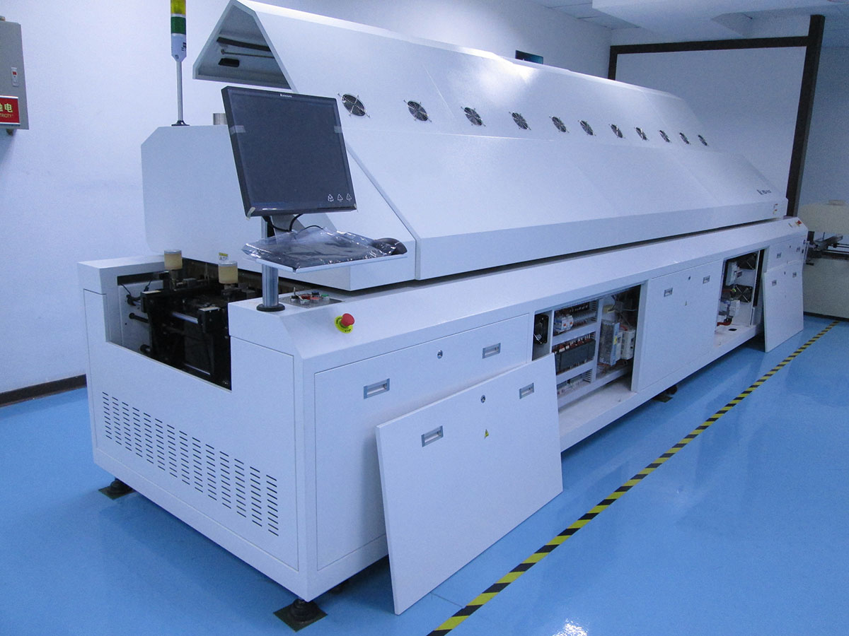
Reflow soldering heat alarm prompt temperature difference is too big or too small, in the process of computer tip ‘communication failure can’t start the machine, according to the two kind of phenomena, we had a lot of test and analysis work, draw the following conclusions:

1, in the process of reflow soldering heat suddenly alarm prompt “temperature range of a certain temperature too low or a certain temperature and set temperature difference is too large”.
Aiming at this phenomenon, we can preliminary judgment fault will occur in the heating or part overheating protection, and so will all overheat protection switch sub let its failure, and start the machine, found that seems to be normal.After further analysis, under the condition of the overheating protection switch sub machine can work, but in the event of heating, the temperature rise too high a less protection of defense, will bring more serious consequences.In order to solve this problem, we must put 16 from heating unit to find out one or several thermal protection switch failure, we will each heating unit with this problem apart, examine its overheating protection switch, found problems the second heating unit overheating protection switch, with a moving contact bimetallic strip fixed weak, cause the moving contact and the static contact point contact is not good, or not at all contact (normally two contacts should be contact together and conduction).Because there is no the second heating unit of the spare parts to replace we will switch sub to ensure production run smoothly.To this can solve the problem, but as soon as possible to the broken overheating protection switch is off, so as to achieve the purpose of protecting the second heating unit.

2, if the downtime is longer, when it turns switched on again reflow computer tip ‘communication failure and can’t start the machine for a long time to let the heat.
Aiming at this phenomenon, we preliminary suspect as the communication line fault, then replaced the telecommunication lines, the question remains, so denied this conjecture.After further observed, when the communication is not successful, the lights on the status of the controller is not normal, orange lights should be flashing, and should not go out.Based on manual measuring line 1001 and line voltage between 1007 found that the voltage is not constant for the + 5 VDC, about + 2 VDC when communication is not successful, the problem is out of here, why the voltage is too low, the original control panel in the end of the machine here are two simulated load resistance, resistance ought to be ‘5’R , but actual value only two ‘2’R, but I have measured the value to change it into ‘5’ R problem is resolved.


SMT,THT,PCB,PCBA,AI,wave soldering,reflow oven,nozzle,feeder,wave solderingLED,PCBA,PCB,LED Lamp,SMT,THT,PCB,PCBA,AI,wave soldering,reflow oven,nozzle,feeder,wave soldering

SMT,THT,PCB,PCBA,AI,wave soldering,reflow oven,nozzle,feeder,wave soldering,PCB Assembly, LED, LED lamp, LED display,

Southern Machinery LED SMT machine S-EF30000 vs Topaz XiII Comparision

Southern Machinery S-EF30000 vs Topaz XiII  Comparision
Model S-EF30000 Topaz XiII Result
No. Item (Southern Machinery Advantage)
1 Spec Speed 36,000 CPH 18,000 cph  double speed, double throughput
2 PCB Size Max: 1200×390mm Max: 460×440   Special design for 1.2m LED tube
3 flexible PCB yes, no need fixture need special make a fixture Suitable for flexible PCB strips
4 PCB loading Manual Approximately 3 sec. saving PCB loading time
5 Applicable components: 0603 to 7474 0201 – SOP, SOJ, PLCC 32mm Suitable for all LED lighting products
6 Machine Config 8 Spindles x 1 Gantry Simultaneous pick with 8  spindles
Fixed Vision Alignment System
8 Mounting accuracy:
(X,Y) 3σ
±0.05(3δ) ±0.10(6δ) chips ± 75µ for chips and SOIC totally enough for LED Chips
9 Mounting angle: 0 up to 360  0 up to 360 (in steps of 0.01)
10 Number of feeders: 16 (12mm) 8mm: 90 positions
11 Machine dimensions : 2,000(L) x 1,150(D) x 1,350(H) 1,650mm(L)x1,408mm(W)x1,850mm(H)
12 Machine weight: Approx. 950kg 1,600Kg
13 Maintenance Cost less $1000.00 per year  $2000.00 per year
14 Machine price $35,000.00  $70,000.00  at least saving 50% money
15 Performance / Price  1.03 (36000/35000) 0.26   (18000cph/$70000)
16 Conclusion: 5 times throughput / cost Advantage to use S-EF30000 produce LED product


SMT,THT,PCB,PCBA,AI,wave soldering,reflow oven,nozzle,feeder,wave soldering,PCB Assembly, LED, LED lamp, LED display, SMT,THT,PCB,PCBA,AI,wave soldering,reflow oven,nozzle,feeder,wave soldering,PCB Assembly, LED, LED lamp, LED display, SMT,THT,PCB,PCBA,AI,wave soldering,reflow oven,nozzle,feeder,wave soldering,PCB Assembly, LED, LED lamp, LED display,

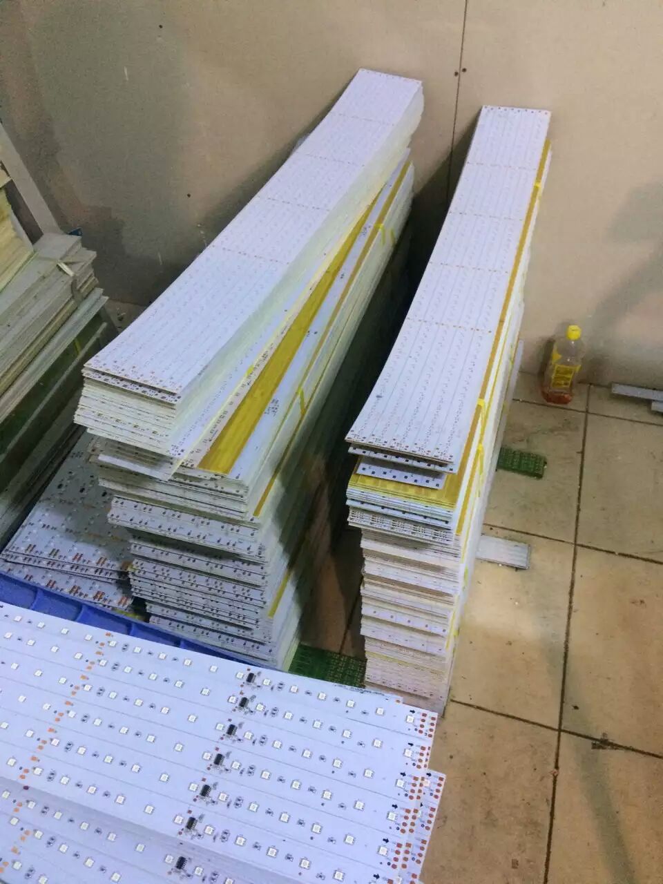
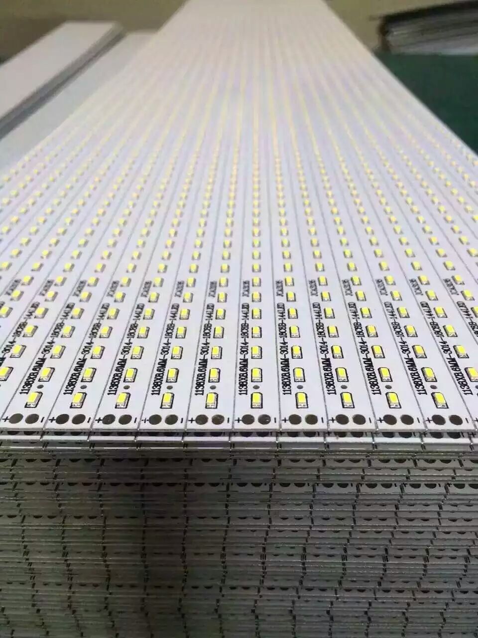
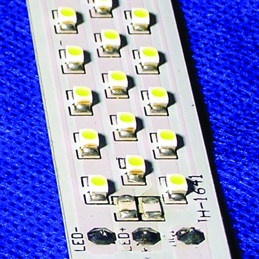
How to gang place in LED pcb assembly

For cost-saving or technical reasons (such as improved assembly), multiple circuit boards may be combined to form one large board, a “panel”. This panel is then produced just as a single large http://bestacnedrug.com circuit board. Consult with us to design the distance of LED chips is same as the spindle distance of placement head.


SMT,THT,Auto Insertion,PCB,PCBA,wave soldering,stencil cleaner,LED,LED tube,LED bulb,LED dispaly,SMT nozzle,SMT feeder

SMT,THT,Auto Insertion,PCB,PCBA,wave soldering,stencil cleaner,LED,LED tube,LED bulb,LED dispaly,SMT nozzle,SMT feeder
OLYMPUS DIGITAL CAMERA
LED,PCB,SMT,PCBA,SMT,THT,PCB,PCBA,AI,wave soldering,reflow oven,nozzle,feeder,wave soldering,PCB Assembly, LED, LED lamp, LED display LED,SMT,THT,PCBA