How to use SMT filter to ensure the quality of SMT products?

SMT Filter

SMT filter cotton is usually replaced in three months, otherwise it will be blocked, affecting the use effect.

Filter has the following characteristics.

1.Is a high performance and high efficiency filter cotton non-woven processing using organic hot-melt synthetic fiber and;

2, increasing structure, using gradually encrypted multi-layer technology, that is, the fiber density in the direction of pure air will increase gradually, and the higher filtration efficiency can be blocked at different levels of density according to the size of dust, which will more effectively accommodate more dust.

3, efficient filter cotton sticky treatment, filter material after full dipping, because the adhesive penetrated the media completely, so that the dust particles can not pass through, so that the overall filtered air flow evenly diffused, forming laminar flow state, to achieve the best spraying effect.


Does anyone need SMT filter cotton? Factory price.

Please feel free to contact us if necessary.

info@smthelp.com

ming@smthelp.net


PCB Board handling system in Smart factory

The Southern Machinery is a Shenzhen-based company, providing professional automatic insertion machines tailor-made for Electronic Manufacturing Factory. Our team works with recognized experts that have many years of working experience in the industry.

As an industry leader with over 20 years of experience in electronic manufacturing, we provide comprehensive guidance from the AI / PCB design (DFM), AIprocess (NPI) to equipment importing, installation, and auto insertion technology (THT) training, machine troubleshooting/ upgrading/ overhauling / relocating/ fittings. We also offer an affordable line-up of all brand spare parts.
By saving your time and money through getting your PCB Assembly automated, your long-term return on invest (ROI) will also increase http://your-pharmacies.com with producing PCBs in-house. Working with a proven industry leader allows you to focus on your core business with PCB assembly handled by the proven specialists at Southern Machinery.
We are committed to conducting any level of EMS design work and providing electronic design services. These value-added design services can verify the accuracy and precision of electronic designs, leading to significant improvements for production output and resulting in superior products with higher quality that your target market will love.

[Canvasio3DPro templateID=”13″ objectID=”14″][/Canvasio3DPro]


[Canvasio3DPro templateID=”14″ objectID=”15″][/Canvasio3DPro]


[Canvasio3DPro templateID=”14″ objectID=”16″][/Canvasio3DPro]


[Canvasio3DPro templateID=”14″ objectID=”17″][/Canvasio3DPro]

How to invest LCD TV Final Assembly factory

Volume Requirements

  • Total estimated time to complete weekly- production volumes with proposed equipment set = 160 hours/per week (+/- 10%)

Notes:

  • Available time is 80 hours (16hours x 5days)!
  • Factory efficiency not optimum due to:
  • Weekly Scheduling
  • Bottle Neck is SM Lines (Top/Bottom)
  • Occupation of Lines, High Volume PC’s
  • For schedule improvements we propose:
  • To add and reconfigure SMT lines, create dedicated HV PC & PC Monitor SM lines
  • Increase inventory, make longer runs, increase weekly batches, warming up Factory

IM Lines

DIP, PCB Assembly,Chip Mounter, Pick and Place, IC Mounter, High Speed Mounter, Wave soldering,LED lighting, LED Lamp, LED Display, LED tube,UPS, Power Converter, Power Adepter, Mobile Charger, PCB board handling system, Loader, Unloader, Conveyor,Shuttle, Chip Mounter, Pick and Place, IC Mounter, High Speed Mounter Induction Cooker, AC, Electric Cooker, Fan, TV, Settle Box

  • Number of Lines : 3
  • Machine Set: Radial S-3000 x 3, Axial S-4000 x 3
  • Cycle time: Average 15 seconds
  • Intrinsic Availability: 90%
  • Mean Time To Repair: 120 seconds

SM Lines

  • Number of Lines : 4
  • Machine Set: High Speed Chip mounter x 2, IC mounter x 1
  • Cycle time: between 12.60 & 25.29 seconds
  • Intrinsic Availability: 90%
  • Mean Time To Repair: 120 seconds

DIP, PCB Assembly,Chip Mounter, Pick and Place, IC Mounter, High Speed Mounter, Wave soldering,LED lighting, LED Lamp, LED Display, LED tube,UPS, Power Converter, Power Adepter, Mobile Charger, PCB board handling system, Loader, Unloader, Conveyor,Shuttle, Chip Mounter, Pick and Place, IC Mounter, High Speed Mounter Induction Cooker, AC, Electric Cooker, Fan, TV, Settle Box

MI Lines

  • Number of Lines : 4
  • Machine Set:
  • 10 x Assembly stations,each line
  • Delta 5 Wave Solder, each line
  • 4 x Test & Inspect stations, each line
  • Average Cycle Time: 25 seconds


DIP, PCB Assembly,Chip Mounter, Pick and Place, IC Mounter, High Speed Mounter, Wave soldering,LED lighting, LED Lamp, LED Display, LED tube,UPS, Power Converter, Power Adepter, Mobile Charger, PCB board handling system, Loader, Unloader, Conveyor,Shuttle, Chip Mounter, Pick and Place, IC Mounter, High Speed Mounter Induction Cooker, AC, Electric Cooker, Fan, TV, Settle Box


LCD TV FA Lines

  • Number of Lines : 2
  • Machine Set:
  • 16 x Assembly stations
  • 3 x L-Shape Soak System 30 min
  • Simulation Soak is 30 min with 30 stations x 3
  • Final QC/Test and Pack Out, 3 stations
  • Two identical Lines (19” to 42”) for optimum Efficiency & Flexibility
  • Average Cycle Time: 24 seconds/station

DIP, PCB Assembly,Chip Mounter, Pick and Place, IC Mounter, High Speed Mounter, Wave soldering,LED lighting, LED Lamp, LED Display, LED tube,UPS, Power Converter, Power Adepter, Mobile Charger, PCB board handling system, Loader, Unloader, Conveyor,Shuttle, Chip Mounter, Pick and Place, IC Mounter, High Speed Mounter Induction Cooker, AC, Electric Cooker, Fan, TV, Settle Box


PCB Assembly,SMT,PCB,AI,THT,LED DIP, PCB Assembly,Chip Mounter, Pick and Place, IC Mounter, High Speed Mounter, Wave soldering,LED lighting, LED Lamp, LED Display, LED tube,UPS, Power Converter, Power Adepter, Mobile Charger, PCB board handling system, Loader, Unloader, Conveyor,Shuttle, Chip Mounter, Pick and Place, IC Mounter, High Speed Mounter Induction Cooker, AC, Electric Cooker, Fan, TV, Settle Box 1 S-4000_副本 S4000-Specification-3 PastedGraphic-3


Ensuring the Best Design for Final PCB Production Stage with Testing!

Ensuring the Best Design for Final PCB Production Stage with Testing! Ensuring the Best Design for Final PCB Production Stage with Testing!

Avoiding Design Mistakes with Testing

Improve EMS Productivity by Testing Early

http://www.smthelp.net/product/high-speed-in-line-circuit-board-test-machine/

PC Board errors are a drain to EMS productivity. Through analysis and testing PCBs in the pilot stages, a smoother and more educated production set-up can be achieved. By performing automatic impedance measurements and testing of components (chip resistors and capacitors) early on, you can ensure the best design for production.

We recommend applying the best design logics when creating your PCB layout and Test, Test, Test for maximum efficiency and output. According to Circuits Assembly’s December 2016 Magazine, here is the list of 5 Most Common PCB Design Mistakes: “1. The components do not suit the production technology 2. Thermal imbalance 3. Incompatibility between fabrication and assembly technology 4. Component placement at PCB edge 5. Placing fiducials on the PCB’s edge.”

Once you have planned your PC Board with best practices, Southern Machinery’s High-Speed In-line Circuit Board Test Machine will help with testing by incorporating a visual inspection function which allows mounting status checks on each component (e.g.: typo descriptions in alphanumeric characters, orientation, size) on the operator’s monitor will serve to best analyze testing up close. As well as automatically generating test data from mounting data and component list.  

http://image.slidesharecdn.com/highspeedin-linecircuitboardtestmachine-fai-161223080028/95/high-speed-in-line-circuit-board-test-machinefai-14-638.jpg?cb=1482480094

http://image.slidesharecdn.com/highspeedin-linecircuitboardtestmachine-fai-161223080028/95/high-speed-in-line-circuit-board-test-machinefai-3-1024.jpg?cb=1482480094

http://www.smthelp.net/product/high-speed-in-line-circuit-board-test-machine/

Are you finding the automatic nozzles cleaner?We can provide!

nozzles cleaner

In the process of SMT, the suction nozzle is quite easily adhered with solder paste or dirt etc. If maintenance has not been done for a long time or the cleaning is not thorough enough while maintaining it, the paste and dirt will be hardened so as to increase the difficulty of cleaning, even it will result in blockage and scraps after long-time accumulation. It practically proves that the S-U24cleaning machine can effectively deal with inflexible solder paste and thoroughly clean the suction nozzle with complex structure.


Equipment size     L× W×H (mm) 505 ×570 ×500
Equipment weight quality 70KG
Cleaning liquor   Cleaning liquor type Industrial purify water
consumption 400CC/H
Liquid used Air source Compressed air
Pressure range 0.5 -0.6Mpa(While cleaning)
Jet pressure 0.4Mpa
Air consumption 280NL/min.or less
Power Voltage AC200-240V
Rated power consumption Max. 200W
Suction nozzle tray Specification Default 24 positions
Object to be cleaned Mounting nozzle  01005-2125

What is First Article Inspection

First Article Inspection overview

Before the manufacturing course begins, business necessities require an in depth verification and comparability of product design vs. manufacturing outcomes, often called First Article Inspection (FAI). Frequently used within the aerospace, medical electronics and automotive industries, FAI studies have gotten an ordinary course of to make sure high quality and consistency of the ultimate product is in order. Although conducting FAI could be advanced, technological developments and person pleasant software programs have allowed customers to implement and execute this course of shortly and precisely.

What is First Article Inspection?

As an official authentication technique for production, FAI intention is to overview and authorize dimensional studies. FAI stories make the most of dimensional properties of a manufacturing like design specs, to make sure of consistency or uncover any deviations. This inspection ensures reliability and repeatability of the manufacturing course, in addition to making certain the producer’s capability to provide elements in accordance with specifications.


What is the aim of FAI?

The goal of a FAI report outlined below:

  1. The FAI report supplies a tenet for goal affirmation that every engineering design and specification is appropriately understood, accounted for, verified and documented.
  2. Ensure the manufacturing course of action is dependable, repeatable and constant
  3. Develops a transparent understanding and communication outlet between purchaser and provider.
  4. Verify the accuracy of drawings, making certain that each adjustments made to any part of the designs are accounted for.
  5. Validate all tooling used for production, guaranteeing the instruments’ capabilities to supply all required elements at defined and accepted speed.
  6. Ensure manufacturing course is succesful and might meets the entiretly of all manufacturing needs.

When is FAI report crucial?

FAI studies are crucial when any of the following occur:

  • A change in design which may probably have an effect on match, kind or operation
  • A change in manufacturing supply, course of action, inspection technique, location of producer, tooling or supplies
  • A change to a special media program that will likely have an effect on match, kind or performance
  • Production has not been executed for 2 years or more (or as specified by buyer)

FAI Benefits

Before proceeding with manufacturing elements, FAI studies will be helpful in figuring out whether or not a production course of action is able to deliver elements constantly within design parameters. Furthermore, FAI studies present construction between buyer and provider for understanding and verifying the final mission necessities. FAI additionally assists buyer and provider with communications and help to avoid future miscommunication. This course of action additionally ensures that you will be using the precise supplies and instruments, offering an efficient initiative for the anticipated outcomes for manufacturing.

Full FAI vs. Partial FAI

A full FAI requires that each field has been accounted for.  With a partial FAI report, any subject missed will affect the FAI sucess. In regards to any excellent fields, they might be crammed out at a later date or utilizing earlier knowledge, on condition that it applies to the precise traits of duplicate elements produced by the identical manufacturing course of action.

FAI Planning

Before the primary manufacturing beings to run elements, many components have to be accounted for with the intention to execute FAI planning, which generally embrace the following:

Records for the manufacturing course of action– manage actions to be executed all through FAI course of and accountable suppliers/organizations.

Ensure authorized  materials sources, laboratory and relevant manufacturing, planning, routing and buying are in accordance with the specifications.

Save

Carrier clip -AI parts

Carrier Clip is the very common wearing parts in Radial insertion machine.

We manufacture the high copy spare parts , promise the quality and keep low cost .

Very welcome to inquiry .
CLICK HERE TO SEND ME A EMAIL

Here is a brief summary about the products we provide:

1.SMT Equipments,include:

  • 1.One stop LED SMT whole line solution
  • 2.SMT peripheral equipments

2.AI Equipments,include:

  • 1.Axial insertion machine
  • 2.Radial insertion machine
  • 3.Odd form insertion machine customed

3.Full Pneumatic Stencil Cleaner

4.

Support non-standard machine customization

5.Accessaries,include:

  • 1.AI machine spare parts and consumables ( Universal,XG ,or others)
  • 2.SMT machine spare parts and consumables(Different brand )

How does SMT electronics assembly work?

Electronics manufacturing using surface-mount technology (SMT) simply means that electronic components are assembled with automated machines that place components on the surface of a board (printed circuit board, PCB).

SMT车间

Electronics manufacturing using surface-mount technology (SMT) simply means that electronic components are assembled with automated machines that place components on the surface of a board (printed circuit board, PCB). In contrast to conventional through-hole technology (THT) processes, SMT components are placed directly on the surface of a PCB instead of being soldered to a wire lead. When it comes to electronic assembly, SMT is the most frequently used process in the industry.

Electronic assembly encompasses not only placing and soldering components to the PCB, but also the following production steps:

  • Applying soldering paste, which is made of tin particles and flux, to the PCB
  • Placing SMT components to the soldering paste on the PCB
  • Soldering the boards with a reflow process.

Applying Soldering Paste

Applying soldering paste is one of the first steps in the SMT assembly process. Soldering paste is “printed” on the boards using the silk-screen method. Depending on the design of the board, different stainless-steel stencils for “printing” the paste onto the board and various product-specific pastes are used. Using a laser cut stainless-steel stencil custom made for the project, the soldering paste to be applied only to the areas where components will be soldered. After the soldering paste is on the boards, a 2D-soldering paste inspection is performed to ensure that the paste is evenly and correctly applied. Once the accuracy of the soldering paste application has been confirmed, the boards are transferred to the SMT assembly line, where the components will be soldered.

AI spare parts、Universal Parts,UIC,TDK.VCD Sequencer.SMT,THT,PCB,PCBA,AI,wave soldering,reflow oven,nozzle,feeder,wave soldering,PCB Assembly, LED, LED lamp, LED display AI spare parts、Universal Parts,UIC,TDK.VCD Sequencer.SMT,THT,PCB,PCBA,AI,wave soldering,reflow oven,nozzle,feeder,wave soldering,PCB Assembly, LED, LED lamp, LED display

Component  Placement and Assembly

The electronic components to be assembled come in trays or reels, which are then loaded into the SMT machine. During the loading process, intelligent software systems ensure that components are not inadvertently switched or misloaded. The SMT assembly machine then automatically removes each component with a vacuum pipette from its tray or reel and places it on its correct position on the board using precise pre-programmed X-Y coordinates. Our machines are capable of assembling up to 25,000 components per hour. After the SMT assembly is completed, the boards are moved on to the Reflow ovens for soldering, which affixes the components to the board.

S-320 pick&place machine

SMT line

Component Soldering

To solder electronic components, we use two different methods, each of which has distinct advantages depending on the order quantity. For series production orders, the Reflow-soldering process is used. During this process, boards are put in a nitrogen atmosphere and are gradually warmed up with heated air until the soldering paste melts and the flux vaporizes, which fuses the components to the PCB. After this stage, the boards are cooled off. As the tin in the soldering paste hardens, the components become permanently affixed to the board and the SMT assembly process is completed.

For prototypes or highly sensitive components, we have a specialized vapor-phase soldering process. In this process, boards are heated until the specific melting point (Galden) of the soldering paste is reached. This allows us to solder at lower temperatures or solder different SMT components at different temperatures depending on their individual soldering temperature profiles.

PastedGraphic-59

AOI and Visual Check

Soldering is the second-to-last step of the SMT assembly process. In order to ensure the quality of the assembled boards, or to catch and correct a mistake, AOI visual inspections are performed for almost all series production orders. Using several cameras, the AOI system automatically checks each board and compares the appearance of each board with the correct, pre-defined reference image. If there are any deviations, the operator of the machine is informed of the potential problem, who then corrects the mistake or pulls the board from the machine for further inspection. The AOI visual check ensures consistency and accuracy in the SMT assembly production process.

Dimensons_floor _layout - A_cmyk

Do you really know how to build a SMT dust-free workshop in LED solution?

Before manufacturing led lights, it’s very important to conduct SMT factory planning, especially for any newly-built SMT factory. New factories have little experience in SMT factory design layout and SMT workshop design so there may be some details lost during the set-up phase. After production begins, discovering problems after the fact can cause unnecessary losses. So why not design your SMT factory layout and plan with these potential issues in mind and prepare in advance? Learn SMT clean mounting workshop production requirements in this article.

LED SMT车间

 SMT workshop production requirements:

1. Workshop bearing capacity, vibration, noise requirements:
Factory ground bearing capacity should be greater than 8 kn/m2.
Vibration should be controlled in less than 70 db, the maximum value of no more than 80db.
The noise should be controlled within 70 dba.
2.  Power supply:
General requirements of single-phase AC220 (220 + / – 10%, 0/60 hz), three-phase AC
380 (380 + / – 10%, 50/60 hz), more than double the power consumption of power supply of power than.
3. Air:
According to the requirement of the equipment configuration of air pressure, can use plant air, and  also be configured individually oil-free compressed air machine, general pressure is greater than 7 kg/cm2.
For clean, dry cleaning the air, so the need for compressed air to oil, dust and water treatment.Made from stainless steel or pressure plastic air duct.
4. Exhaust:
Reflow soldering and wave soldering equipment need exhaust fan.For hot blast stove, exhaust pipe of the minimum flow rate value is 500 cubic feet per minute (14.15 m3 / min).
5. Lighting:
In the ideal of the plant Illumination is 800 ~ 1200 lux, at least not less than 300 lux, when low intensity of illumination, in the inspection, repair, measurement work areas should install local lighting.

6. Work environment:
Factory to keep clean, no dust, no corrosivegas.Production workshop should have cleanliness control, control the cleanliness: the class of 500000.
Production workshop environment temperature to 23 + / – 3 ℃ is the best, average of 17 ~ 28℃,relative humidity is 45% ~ 45% RH.

Save

Grease / Oil for Electronic Manufacturing SMT machine

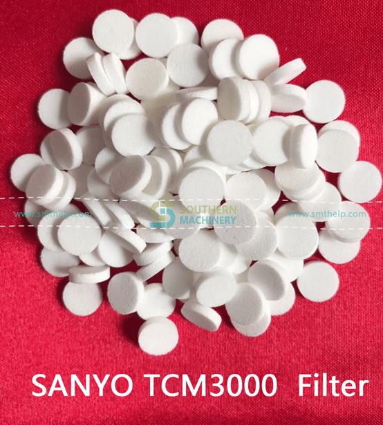
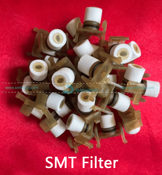
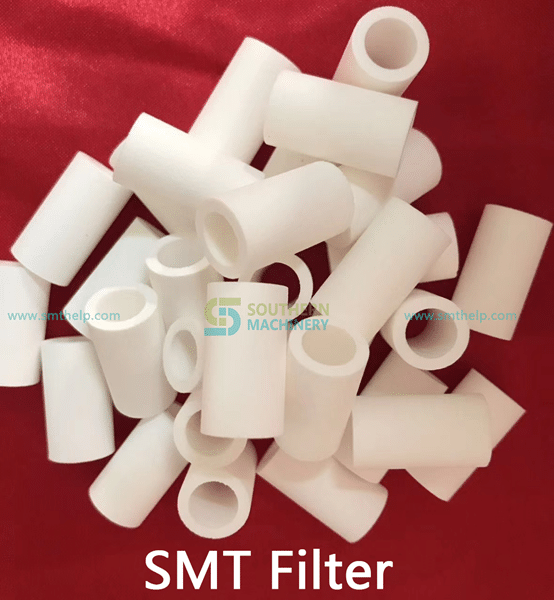
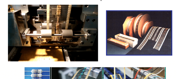
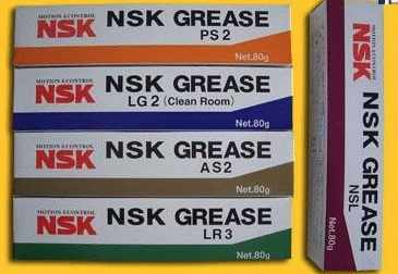
We provide a variety of Grease /  Oil for Electronic Manufacturing SMT machine

NSK Series lubricants


NSK NSL oil is linear guide for oil.

NSK PS2 is a high- precision high-speed grease lubricants . Use advanced synthetic base oils , urea thickener and special additives , has excellent corrosion resistance and abrasion resistance and long service life , suitable for high speed , the temperature, the use of small high-speed machinery , suitable temperature is 190 degrees.

nsknks66331428570405

NSK LG2 grease lubricants are dedicated clean room , pollution , specifically for semiconductors,

20141104102434_9888

LCD manufacturing equipment and food machinery.

NSK AS2 oil is heavy , waterproof anti- corrosion grease with precision .

PastedGraphic-9

NSK LR3 grease lubricant is high temperature and high precision .

 PastedGraphic-10

NSK GREASE NSL

Lubricants for linear guide for oil, mainly used in our industry Yamaha SMT machines, special screw on the Y -axis X -axis , because the parts at high speed while the ball requires a lot of lubrication, because this oil has excellent wear characteristics , can effectively inhibit the high-speed friction problem when used .

Packing : 80G / branch ;AI spare parts、Universal Parts,UIC,TDK.VCD Sequencer.SMT,THT,PCB,PCBA,AI,wave soldering,reflow oven,nozzle,feeder,wave soldering,PCB Assembly, LED, LED lamp, LED display

Manufacturer : NSK CO, LTD Seiko Corporation . .

Usage: can be used with Japanese NSK HGP oil gun to use , but also with THK MG70 grease guns , shaped nipple tubing complete SMT equipment maintenance refueling dedicated .


NSK GREASE PS2

● Features

The main component of the base oil used in synthetic and mineral oil , having excellent lubricating properties of the high-speed driving at a low temperature with a light load in terms of grease .

● Use it NSK miniature ball screw linear guide and standards adopted lubricant. Although it is very excellent driving characteristics of low-temperature lubricant , at room temperature, but also has good turning characteristics , it is very suitable for precision load small precision machine.

In our industry, mainly for the private placement on a Yamaha machine, low speed bearings and sliders, shortcomings , the temperature is not high , wear is not very good .

Packing : 80G / branch ;

Manufacturer : NSK CO, LTD Seiko Corporation . .

Usage: can be used with Japanese NSK HGP oil gun to use , but also with THK MG70 grease guns , shaped nipple tubing complete SMT equipment maintenance refuel special .


GREEN NS7

NSK GREASE NS7 lubricants, adapt the temperature from -40 ℃ to 140 ℃ to some extent can be used for a wide range of temperatures. The product is a low base oil viscosity , good lubricating properties.

Features:

A high durability and excellent performance, long-life grease

2 low-temperature performance and excellent mechanical properties at high speed during operation , some oil leakage.

3 .. low wear, at room temperature , in order to reduce bearing friction torque.


5 grease excellent performance can be maintained for a long period of time.

6 to have excellent water resistance .

(7) The effect of the product can reduce the brine excellent rust device

Which products for FUJI SMT , NXT and CP842 dedicated

Packing : 80G / branch ;

Manufacturer : NSK CO, LTD Seiko Corporation . .

Usage: can be used with Japanese NSK HGP oil gun to use , but also with THK MG70 grease guns , shaped nipple tubing complete SMT equipment maintenance refueling dedicated .

NSK LR3

● Features

     Refined mineral oil in the base oil, grease, and a lithium-based thickener additives of special abrasion resistance, excellent extreme pressure resistance of the pan with a large load with grease. It has the load resistance and excellent oxidation stability , maintain good lubrication performance for a long time , and with high lubrication life. Excellent water absorption , even in the state contains a lot of water under , it will not be washed away by the water softener .

● Use

     It is common grease NSK linear guide and ball screw standards adopted . Oil dynamic viscosity, excellent load resistance , oxidation stability is also very good , it can be widely used for various purposes , is a common type of grease used .

In our industry, mainly for Yamaha SMT machines, special bearing on l , paragraph grease lubricants are high temperature and high precision , large-scale metal processing machine tool spindle bearings specifically for high-speed , high-temperature , high load for the girth greater than 62MM high-speed bearings , which can effectively improve the machining accuracy and extend bearing life.

Packing : 80G / branch ;

Manufacturer : NSK CO, LTD Seiko Corporation . .

Usage: can be used with Japanese NSK HGP oil gun to use , but also with THK MG70 grease guns , shaped nipple tubing complete SMT equipment maintenance refueling dedicated .


NSK GREASE LG2 / NSK GREASE LG2 (Clean Room)

Features: The grease used as a clean room of the Department of straight rails and ball screws and other special grease , developed by NSK alone products, with the original clean room compared to the commonly used fluorinated grease , it has a high lubricity, lubricating long life, stable fat torque characteristics ( slip resistance ) , etc. , also have high rust resistance and dust characteristics , to achieve the same grease better than other low dust characteristics. Furthermore, not a special base oil used instead of mineral oil , the same method can be used ordinary lubricants.

Uses: For high cleanliness requirements of semiconductor , liquid crystal lubricant Linear Guides (LCD) manufacturing equipment , such as the use of a ball screw and rotating products. But the pressure of the grease dedicated clean environment , it can not be used in a vacuum environment .

 In our industry, mainly for Yamaha SMT , COB bonding machine.

Packing : 80G / branch ;

Manufacturer : NSK CO, LTD Seiko Corporation . .

Usage: can be used with Japanese NSK HGP oil gun to use , but also with THK MG70 grease guns , shaped nipple tubing complete SMT equipment maintenance refueling dedicated .


NSK GREASE AS2

One can withstand , with a gravity well.

Second, the continuing good , good adhesion, good adhesion .

Third, the product has a certain acidity , resistant to corrosion.

Fourth, a strong water resistance.

Disadvantages : The temperature is not good, poor wear resistance.

In our industry, mainly for Yamaha SMT machines , special placement head , because this part of the low-speed operation , while only need to play a minor slip can be lubricated . Packing : 80G / branch ;

Manufacturer : NSK CO, LTD Seiko Corporation . .

Usage: can be used with Japanese NSK HGP oil gun to use , but also with THK MG70 grease guns , shaped nipple tubing complete SMT equipment maintenance refueling dedicated .

PCBA Quality Process Audit — SMT Pick and Place machine

1. Work Instructions
1.1 Is there a revision controlled Operator Work Instruction which contains loading information for the specific product being built? (Score 0 if any unsigned/undated handwritten instructions or any handwritten instructions more than 48 hrs old)
1.2 Are Work Instructions readily available to the operator and are they followed at Component Placement?
1.3 Are component part numbers and descriptions included on the Work Instructions?
1.4 Are component descriptions sufficiently detailed to check at first-article that the correct components are being used?
1.5 Is the machine head/slot number for component loading specified for each part number on Work Instructions?
1.6 Are the reference designators and the quantity per part number specified on Work Instructions?
1.7 Is the component feeder type/size specified on Work Instructions or otherwise for each component package type?
1.8 Is the machine Program Name specified on the Work Instruction or line set-up instructions?
2. Component Loading and Verification
2.1 Is there an automated bar coded component loading verification aid in order to reduce the probability of incorrect loading? Note*
2.2 Are the component loading verification aids hard linked to the placement program so that loading is verified against program data?
2.3 Can traceability of component lot codes be demonstrated for critical devices?
2.4 Is component loading/changes verified and cross checked by an individual other than the set-up operator at product changeover? Note*
2.5 Is a component loading/changes verification log signed by the set-up operator and countersigned by the cross checker before start up? Note*
2.6 Is the correct feeder loading base used to facilitate real to feeder loading?
2.7 Are first-built boards verified against documentation for missing/misplaced components and for correct component polarity?
2.8 Are first-articles conducted using AOI methods and complemented with description verification and value metering?
2.9 Are all Resistors & Capacitors measured for a value within the tolerance (one per part number) at first-article & at reel change?
2.10 Is a first-article log signed to verify acceptance before start up?
2.11 Is the orientation of Tantalum SMT capacitors, Diodes, etc in tape format, standardized and documented for polarity orientation?
2.12 Is the IC tray loading polarity standardized for each type of polarity indicator that can be used for each component?
2.13 Is loading polarity referenced both from the tray and the component so as to ensure retrayed components are correctly loaded?
3. Nozzles, Feeders, and Tooling
3.1 Is there a document which details the standardized nozzle diameter set-up selected for each type of placement equipment?
3.2 Are these standardized nozzle diameter set-up documents readily available for when nozzles need to be replaced or changed?
3.3 Is there a document which details the range of component XYZ body sizes that each selected nozzle type can successfully place?
3.4 Is there a documented requirement to conduct daily nozzle centering and is there evidence that this is done?
3.5 Is each feeder identified with its own unique serial number?
3.6 Is there a documented and effective Feeder Maintenance Program? Records (s/w or otherwise) must be by Feeder Serial Number.
3.7 Are database records maintained for each feeder serial number for the purpose of tracking its maintenance history and performance?
3.8 Is feeder maintenance history used to monitor feeder life so that problematic feeders can be removed from the process?
3.9 Can it be demonstrated that the number of feeder indexes is counted & monitored for each unique feeder using software or otherwise?
3.10 Is this information used to flag that feeder preventative maintenance is required after x number of indexes?
3.11 Is there a documented requirement to indicate that Blocks or Support Pins are needed for specific products?
3.12 Is the No, location, type and height of Support Blocks/Pins identified on a product by product basis? Score NA if in 3.11 there are not needed.
3.13 Are the Support Pin locations identified for each product using templates/tooling or some other effective solution? Comment as above.
4. Moisture Sensitive Devices
4.1 Are components stored before loading and after unloading in a manner which prevents damage?
4.2 Are the Moisture Sensitive Devices (MSDs) and their sensitivity level readily known to the operator?
4.3 Are MSDs time stamped at opening and their exposure time monitored against pre determined limits?
4.4 Is there a flag to indicate that the exposure time has been exceed for any given device in a dry box?
4.5 Is there a flag to indicate the MSD exposure has expired for any MSD device currently loaded in the placement machines?
4.6 Have MSD procedures been updated to reflect the JEDEC standard for MSD control? (J-STD-033A MSD released in July 2002)
4.7 Is there evidence of correct implementation of J-STD-0033A for all MSD devices?
4.8 Are there MSD procedures in place to ensure MSD shelf life is reduced based on measured Relative Humidity conditions?
4.9 Is there a method in place to address the time spent in dry storage and its effect on remaining life based on MS Level and RH Level?
4.10 Is it clearly understood that MSD ‘shelf life’ continues to degrade during dry cabinet storage of some MSD devices?
4.11 If MSDs are on both sides of a PCBA, is there an effective method to account for time between 1st and 2nd reflow?
4.12 Can MSD control be demonstrated for MSD devices that need internal/external pre-programming?
4.13 Can MSD control be demonstrated for rejected devices and devices used for rework?
4.14 Have MSD recovery methods been defined and adequate for all component types?
4.15 Does the control of Moisture Sensitive Components include those components on reels?
4.16 Is the baking or hot room storage time and temperature documented and controlled for component recovery?
4.17 Has this time and temp been determined based on the component supplier’s guidelines / J-STD-0033A?
4.18 Is there evidence to demonstrate that the control process for MSDs is in use and is effective?
5. Machine Capability
5.1 Are Component Placement Programs generated from CAD XY coordinate data?
5.2 Is there a standardized nomenclature for Shape Code definition?
5.3 Can this nomenclature be used to determine the most appropriate shape code to allocate to a given part of given dimensions?
5.4 Are localized fiducials used for fine pitch devices when localized component fiducials exist on the board?
5.5 Has manual component moving been eliminated given correct CAD, nozzle set-up, Shape Code allocation, local fiducials, Cam speed, etc?
5.6 Does the Fine Pitch placement machine have the capability to check lead Coplanarity in xyz?
5.7 Does the Fine Pitch placement machine use its coplanarity capability on all leads of 20 mil pitch or less, and all programmed parts?
5.8 Does the Fine Pitch placement machine have the capability to check ball arrays? If no such device, score NA.
5.9 Does the Fine Pitch placement machine use its ball array verification capability for all BGA devices? If no such device, score NA.
5.10 Is the machine Program Name revision controlled to show traceability of program changes?
5.11 Is the machine Program Name traceable to the PWB and PCBA part number?
6. PCBA
6.1 Are outputted boards at least sample inspected pre reflow for placement positional accuracy for machine control purposes?
6.2 Is the frequency for this verification defined and documented, and is there evidence to suggest it is followed?
6.3 Is there a visual aid available which identifies the populated locations with polarity, and also the no-pop locations?
6.4 Is there a placement standard pre reflow to validate placement accuracy for the shape code, nozzle allocation, etc. parameters used?
6.5 Is there evidence to demonstrate that action is taken to adjust the machines performance for when this standard is exceeded?
7. Attrition Rates and Rejected Components
7.1 Is attrition rate monitoring conducted systematically to ensure feeder and/or nozzle problems are captured at least hourly?
7.2 Is there documented evidence to ensure attrition rates are checked and actioned at least hourly to ensure process control?
7.3 Is there a specification defined for acceptable attrition rates for the individual feeders?
7.4 Is there a specification defined for the maximum allowable number of nozzle skips per machine before it is shut down for repair?
7.5 Are these specifications determined based on a percentage combined with the number of placements for a given time period?
7.6 Is there evidence to demonstrate that attrition rate monitoring is conducted, effective, and used to make process control decisions?
7.7 Is there a documented process for the disposition or reuse of machine rejected components? Rs and Cs must not be reused even for rework.
7.8 Are rejected components reviewed and repaired to ensure conformance before reuse, even if only used for rework?
7.9 Are there repair blocks available or a lead conditioner in use for repairing ‘real’ Coplanarity rejects? Score 0 if parts not repaired.
7.10 Does the re-traying process always ensure that component polarity wrt the tray and the component loading polarity is preserved?
7.11 Is there a documented Process Deviation procedure to manage machine skips for hand placement if hand placement is allowed?
8. Process Capability
8.1 Has a Process Capability Analyses (PCA) been conducted and the Cpk acceptable for the suite of shape codes in use?
8.2 Were shape code allocations, component nozzle allocations, cam speeds, etc. recorded for this PCA?
8.3 Are the recorded shape code allocations, component nozzle allocations, and cam speeds, the same as those used today?