SMC Fittings — Universal SMT and Auto Insertion machine Spare Parts P/N

  C D
1 UIC P/N SMC DESCRIPTION
2 DW-3-10A D-J59L
3 FDJJ-11300 D-C73
4 VCD-4998 NCDGBN50-0200-XC37
5 VCD-5002 NAS3201F-N02-11S
6 VC080505 KJL04-M5
7 30581402 KQL05-34S
8 30885706 DO NOT USE
9 30885705 DO NOT USE
10 40135602 NCDRA1BS80-180C-F5P
11 40834504 KQU11-36S
12 40835912 TU0425B-20
13 40835914 TU0805B-20
14 40835915 TIUB01B-20
15 40835916 TIUB01BU-20
16 40835917 TIUB01Y-20
17 40835918 TIUB05B-20
18 40835919 TIUB05BU-20
19 40835920 TIUB05Y-20
20 40835921 TIUB07B-20
21 40835922 TIUB07BU-20
22 40835923 TIUB07Y-20-X4
23 40835924 TIUB11B-20
24 40835925 TIUB11BU-20
25 40835926 TIUB11Y-20
26 40835927 TIUB13B-20
27 40835928 TIUB13BU-20
28 40835929 TIUB13Y-20
29 40835930 TU0425Y-20
30 40835931 TU1065C-20
31 40835932 TU0425BU-20
32 41679601 NAS1200-U10/32
33 41679602 NAS2200-N01
34 41679603 AS1210-U10/32
35 41679604 NAS2210-N01
36 41679605 NAS2200-N02
37 41679606 NAS2210-N02
38 41679607 NAS3200-N02
39 41679608 NAS3210-N02
40 41679609 NAS3200-N03
41 41679610 NAS3210-N03
42 41679611 NAS4200-N04
43 41679612 NAS4210-N04
44 41757301 KQU07-00
45 41757302 KQU05-00
46 41757303 KQU03-00
47 41757304 KQ2U11-13
48 42126001 D-G59
49 42126101 NBA-150
50 42404701 BJ1-15
51 42404801 D-G79
52 42609601 IN-289-138
53 42638201 NCDJ2B10-100R-H7A1
54 42740601 KQL05-35S
55 42740602 KQL07-36S
56 42740603 KQL13-36S
57 42740604 KQL07-34S
58 42740605 KQL07-35S
59 42740606 KQL13-37S
60 42740607 KQL11-37S
61 42740608 KQL13-35S
62 42740609 KQL07-32
63 42740610 KQL01-34S
64 42740611 KQL11-36S
65 42740612 KQL11-35S
66 42740613 IN-289-540S
67 42740614 KQL03-32
68 42740615 KQL03-34S
69 42740616 KJL03-32
70 42740618 KQL09-34S
71 42740617 KQW13-36S
72 42740619 KJL07-32
73 42740620 KJL01-32
74 42740621 KQL09-36S
75 42740622 KJL07-34S
76 42740624 KQ2L07-34S
77 42741700 KQR07-07
78 42741701 KQR05-07
79 42741702 KQR07-11
80 42741703 KQR01-05
81 42741704 KQR03-07
82 42741705 KQR07-09
83 42741708 KQR09-13
84 42766201 KQH03-32
85 42766301 AS1201F-U10/32-03
86 42767001 NCY2B15H-2512
87 42769001 ZCUCK-10-25D
88 42783408 KQT11-35S
89 42823101 D-G79L
90 42851001 KQH05-34S
91 42851002 KQH07-35S
92 42851003 KQH13-36S
93 42851004 KQH13-37S
94 42851005 KQH07-34S
95 42851006 KQH07-36S
96 42851007 KQH11-35S
97 42851008 KQH13-35S
98 42851009 KQH01-32
99 42851010 KQH07-32
100 42851011 KQH11-36S
101 42851012 KQH01-34S
102 42851013 KQH01-33S
103 42851014 KQH03-34S
104 42851015 KQH09-35S
105 42851018 KQH10-02S
106 42880201 NJ10-32
107 42941601 KQU07-34S
108 42941602 KQU07-35S
109 42941603 KQU13-36S
110 42941604 KQU07-36S
111 42983401 KQT07-34S
112 42983402 KQT07-35S
113 42983403 KQT07-36S
114 42983404 KQT01-34S
115 42983405 KQT01-35S
116 42983406 KQT05-34S
117 42983407 KQT05-35S
118 42983408 KQT11-35S
119 42983409 KQT11-36S
120 42983410 KQT11-37S
121 42983411 KQT13-35S
122 42983412 KQT13-36S
123 42983413 KQT13-37S
124 42983414 KQT03-34S
125 42984001 KQH01-00
126 42984002 KQH05-00
127 42984003 KQH07-00
128 42984004 KQH11-00
129 42984005 KQH13-00
130 42984006 KQH03-00
131 43095901 BJ1-10
132 43107801 KQP-01
133 43107802 KQP-05
134 43107803 KQP-07
135 43107804 KQP-11
136 43107805 KQP-13
137 43107806 KQP-03
138 43214001 KQE01-00
139 43214002 KQE03-00
140 43214003 KQE05-00
141 43214004 KQE07-00
142 43214006 KQE11-00
143 43251101 ZSE1-T1-15
144 43261501 KQT07-00
145 43261502 KQT13-00
146 43261503 KQT11-00
147 43261504 KQT01-00
148 43261505 KQT05-00
149 43261506 KQT03-00
150 43261601 KQY07-34S
151 43261602 KQY07-35S
152 43261603 KQY13-36S
153 43261604 KQY11-35S
154 43261605 KQY13-35S
155 43261605 KQY13-35S
156 43261803 KQT11-00
157 43266301 KQL07-11
158 43266302 KQL01-05
159 43266303 KQL11-13
160 43266304 KQL09-13
161 43266305 KQL07-99
162 43266306 KQL01-99
163 43318801 NCRB1BW15-180S
164 43318802 NCRB1BW30-90S
165 43318803 NCRB1BW30-180S
166 43382501 NAS2201F-N01-05S
167 43382502 NAS2211F-N01-05S
168 43382503 NAS2201F-N01-07S
169 43382504 NAS2211F-N01-07S
170 43382505 NAS2201F-N02-07S
175 43628501 NCJPB10-050D
176 43628502 NCDJPB10-050D
177 43686601 AN120-M3
178 43704301 NCY2B10H-1875
179 43704302 NCY2B10H-1075
180 43705201 NCY2B10H-UIA950244
185 43705202 NCY2B10H-UIA960023
186 43819201 IN-289-179S
187 43844901 NCRB100-180
188 43955202 NCY2B10H-1600
189 43955203 NCY2B10H-UIA950332
190 43955204 NCY2B10H-UIA990381
191 43961301 NCMW075-0125
192 44134401 CY2B10H-599
193 44134701 CRB1BW10-UIA970726
194 44236701 NVHS2500-N03-X116
195 44292301 VJ10-13-1
196 44292302 AXT661-12
197 44292401 DXT170-71-1
198 44292501 DXT170-38-3
199 44317501 ZSM1-T115
200 44360302 D-F79
201 44426001 NZX1071-K16LOZ-X156
202 44498301 NVHS3500-UIB960168
203 44544302 NCRB1BW10-90SE
204 44601704 CVJ5D12-UIA970124
205 44601706 CVJ5D12-UIA970125
206 44601707 CVJ5B12-G0663-25
207 44601708 CVJ5D12-UIA970123
208 44601709 CVJ5D12-UIA970010
209 44601710 CVJ5D12-UIA970009
210 44611301 KQL13-00
211 44611302 KQL01-00
212 44611303 KQL03-00
213 44611304 KQL05-00
214 44611305 KQL07-00
215 44611306 KQL11-00
216 44718601 ZZX108-UIB950112
221 44718602 ZZX108-01-0027US
222 44718603 ZZX108-UIB950347
223 44748101 JA15-5-080
224 44781901 ZSE2-T1-15
225 44935603 CVJ5D12-48-0034US
226 44970901 NCDY2S6H-0375-F79
227 45078201 NCA1-C250
228 45078301 NY-150
229 45079201 NCA1-D250
230 45175202 NVKF334-6G-X7
231 45112501 ZZX108-01-0028US
232 45175001 ZSE1-T1-15
233 45175201 NVKF334-UIB950148
234 45175202 NVKF334-6G-X7
235 45176101 CJ2RA1D-G0999-63.5
236 45242901 KQL13-99
237 45360301 KQU07-99
238 45360302 KQU03-99
239 45435901 KQW13-35S
240 45435902 KQW07-35S
241 45435903 KQW07-34S
242 45527501 CJPB10-10-B
243 45619401 ARJ1020F-M5-04
244 45627301 VJ10-01-0012US
245 45641201 NCY2B25H-3642
246 45710001 AS2001F-06
247 45710002 KQU06-00
248 45712401 NZZX1-01-0033US
249 45845701 KJS03-32
250 45845702 KJS01-32
251 45871302 NAC2020-UIB970079
252 45871304 NAC2020-UIB980480
253 45871305 NVHS2500-UIB980483
254 45871402 NVV5J3-UIB960292
255 45871409 SS5YJ3-UIB980495
256 45871410 SS5YJ3-UIB980496
257 45871411 SS5YJ3-UIB980497
258 45880401 KSL03-32
259 45880402 KSL03-32
260 45880403 KSL07-34S
261 45892401 NZX1072-01-0034US
262 45900701 NCDGBN20-01-0278US
263 45900702 NCDGBN20-01-0266US
264 45900703 NCDGBN20-UIA970715
265 45903901 D-H7A1
266 45903902 D-H7A1L
267 45903903 D-H7A2L
268 45904001 MGQL25-40-XC18
269 45904003 MGQL20-15-XC18
270 45904004 MGQL25-20-XC18
271 45904101 D-Y59A
272 45904102 D-Y7PL
273 45907701 AS2201F-U01-07
274 45921401 ZP06US
275 45932701 NZX1071-UIB9800027
276 45974601 ZX1-FE
277 46035801 NVHS2500-N01-X116
278 46035901 NAC2020-N01G-C
279 46036001 NVZ512-5LZ-01T
280 46036101 NVV5J3-46-03-B3T
281 46036102 SS5YJ3-41-04-M5T
282 46036104 NVV5J3-41-02-M5T
283 46036106 SS5YJ3-41-05-M5T
284 46036201 SYJ3140-5LZ
285 46036202 SYJ3140-5LZ-M5
286 46036203 SYJ3140-6LOZ
287 46036204 SYJ3140-6LZ
288 46036301 SYJ3000-21-1A
289 46036401 NAR1000-M5
290 46036501 NAS2201F-N01-03S
291 46045801 NCJPB10-125D
292 46045802 NCJPB10-037D
293 46064601 NCQ2WB20-UIA950021
294 46073801 VJ10-13-1
295 46073901 DXT170-71-1
296 46074401 ARJ1020F-M5-04
297 46075901 NVZ512-UIB960184
298 46106701 MGQL12-30-Y69A-XC18
299 46108001 NZX1131-K15LZ-E55CL
300 46188901 BMA2-020
301 46215001 NCDQ2B12-15D-F79
302 46215101 D-Y69
303 46215201 D-F79
304 46228501 NAS2001F-03
305 46228502 NAS2051F-07
306 46230701 VJ10-20-4A-20
307 46230702 SY100-30-4A-15
308 46230703 SY100-30-4A-25
309 46234201 BA-02
310 46266902 NCDGKBN20-UIA960254
311 46268501 NCDJ2B10-100S-B
312 46268701 SY114-BLOZ-M3
313 46268702 SY114-6LOU-M3
314 46275501 TCU0425B-2
315 46278601 NCJ2D10-ULA950095
316 46303801 K-477-000001
317 46303901 KJL04-M3
318 46314601 SYJ3120-UIB960387
319 46314701 NVJ3140-UIB960143
320 46334301 KQH11-34S
321 46356401 NVKF334-UIB960007
322 46386601 AN120-M3
323 46386701 NAN103-N01
324 46396401 BJ2-010
325 46419401 NVM830-N01-13
326 46419901 NCRA1BS50-90C
327 46436501 CJ2B10-22
328 46436502 CJ2B10-ULA970015-B
329 46446801 NCGBN20-0112
330 46446802 NCGBN20-0062
331 46466301 MKA20-10R
332 46492801 NAS2301F-N01-03S
333 46492802 AS1301F-U10/32-03
334 46492804 NAS2301F-N01-07S
335 46494003A K-477-9900001
336 46494301 UIUSP-97011
337 46494302 D-477-980001G
338 46501201 NZZM02-T06R
339 46501301 ZZM-SA
340 46523801 TU0604B-20
341 46523901 KQR06-04
342 46533401 NAR2000-N01BG
343 46533501 NAS2051F-07
344 46536201 NZM133HT-K6LZ
345 46536301 NZHI13BL-T01-T02
346 46558301 NZL112-E25L
347 46558302 NZL112-K15LZ-E25L
348 46558303 NZL112-K16MZ-G-X125
349 46558401 VQ1171-5LO
350 46558501 VV5Q17-03C-D
351 46560501 NZX1101-UIB970005
352 46560502 NZX1101-K15LZ-D21C
353 46561101 CDQ2KL20-UIA960056
354 46561102 CDQ2KA20-UIA980842
355 46564501 VVQ1000-50A-N7
356 46564502 VVQ1000-50A-C4
357 46564503 VVQ1000-50A-M5
358 46564504 VVQ0000-58A
359 46564505 VVQ1000-5DA-C6
360 46566101 AXT100-DR-8
361 46566502 VV5Q17-UIB960084
362 46568501 NVKF332-5GZ-M5
363 46614001 VQ110U-6L
364 46614002 VQ110U-48-ULA960095
365 46628001 P3200118
366 46642901 SY3120-UIB960318
367 46642902 SY3120-UIB960167
368 46665701 NCDJ2B6-050-H7A1S
369 46670601 NCDGBN20-UIA970003
370 46670602 NCDQ2A20-UIA990332
371 46676301 NCGBN20-UIA960384
372 46677901 NCQ2B32-UIA960433
373 46734502 NZHI07BS-07-07
374 46677902 NCQ2B32-UIA960395 (OBSOLETE)
375 46748501 NCJ2B16-075
376 46748503 NCJ2B16-100
377 46748601 NCGBN20-0087
378 46760102 UIUSP-97042
379 46760201 NCJ2WB10-ULA960095
380 46801601 NCJ2KB16-150
381 46804301 CQ2A12-10S-XA00B
382 46804701 TCU0425B-1
383 46823101 NY-J010B
384 46828101 M-3AU-4
385 46828102 M-3AU-3
386 46828201 M-3P
387 46831801 NZL112-K1-G-X108
388 46878601 NCDJ2QF10-ULA000136
389 46878602 NCDJ2B10-100T-H7A1S
390 46882201 KJL03-07
391 46882301 KJX03-07
392 46882302 KQU04-99
393 46913301 NCQ2WB50-UIA990824
394 46916901 NVM130-N01-33
395 46917001 NCJ2B16-100S
396 46932002 SY5120-6G-01T
397 46939801 NVSA3135-03N
398 46943001 KQS07-34S
399 46943002 KQS07-32
400 46975501 KQU01-00
401 46984301 NVKF332-6G-01T
402 46997004 CXSM15-30
403 46997006 NCQ2B25-10D
404 47006501 SY3120-6HU0N7
405 47019101 SY3120-6LZ-M5
406 47035701 NAQ1510-N01
407 47044401 KJH01-32
408 47046401 SY5120-UIB970218
409 47049301 NCGBN20-0250
410 47058301 M-5ALU-4
411 47062801 AS1200-M3
412 47097501 SS5YJ3-UIB960266
413 47109801 NCQ2WB50-40D
414 47119301 NZHI07DS-07-07-07
415 47128501 MXS8-20AS-F9N
416 47128601 NCDQ2B12-10DM-F79
417 47128701 NCDQ2D12-10DCM
418 47128801 NCDGCN32-0050-G59
419 47128901 NCJ2L10-100
420 47129201 SY3120-6LZ-M5
421 47130801 SS5Y3-20-06-00T
422 47131701 TM-04
423 47133001 NCG-PC032
424 47133101 Y-G012
425 47133201 AS1211F-U10/32-03
426 47134101 CDQSB16-10D
427 47137801 RSQA20-20T-XC18
428 47146801 NCGKWBN25-0100-97069CDN
429 47149402 NCGBN20-UIA990747
430 47158601 NAN101-N01
431 47158602 AN120-M5
432 47162001 NCQ2B32-75DCM
433 47162201 NJ05
434 47162301 NVZ5120-6LZ-01T
435 47182001 NCQ2B20-UIA970132
436 47184001 SY5120-UIB980032
437 47184101 SY3120-UIB970354
438 47207501 VJ10-20-4A-15
439 47207601 NZHI13BS-T01-T01
440 47207801 TMH-07
441 47240001 NAW2000-N02-C
442 47240201 NAV2000-N02-5GS
443 47240301 GP46-P10-N01-X7
444 47240801 UIUSP-97057
445 47241801 D-477-980002B
446 47257301 VQ110U-6M
447 47257302 VQ110U-6MO
448 47257401 M-5AU-4
449 47278201 NZM-SF
450 47308801 SY5120-6HU-01T-F2
451 47310901 RCD-01
452 47329201 NCDJ2D16-070-B
453 47329202 NCJ2D16-150
454 47329301 NY-J015B
455 47341301 MXS12-20AS-X11
456 47341901 AS1301F-U10/32-01
457 47355502 VQD1151-5M-M5
458 47355504 VQD1151U-6MO
459 47355506 VQD1151U-5M
460 47356801 KJU04-00
461 47376401 NCQ2B50-45D
462 47376901 NAS2301F-N02-07S
463 47377301 SYA5140-02N
464 47402601 NY-J010
465 47402701 NCDJ2D10-ULA980109
466 47421702 KQ2T03-07
467 47422101 KJS07-33S
468 47463501 KJS04-M3
469 47493601 KJH03-32
470 47504501 NVKF334-UIB980419
471 47511601 CQ2B20-10D
472 47511602 CQ2B20-5D
473 47514401 NZM131HT-K5LZ
474 47514502 ZSE40-T1-22 OR ZSE40-T1-22L
475 47538001 KM11-07-11-6
476 47538002 KM11-11-13-10
477 47560802 SPECIAL “Z” #-NEED P/N SWITCH
478 47561902 D-477-980002A
479 47561904 D-477-980002C
480 47561905 D-477-980002BP
481 47570101 SS5YJ3-UIB980536
482 47574002 VQZ235-6LO
483 47587201 NRBC037-025
484 47594501 NZX1101-EC
485 47597201 KQ2C07-00
486 47598401 TCU0425B-1-4-X6
487 47598701 K-477-9800009-A
488 47605501 MGQM12-25-XC18
489 47607601 CQ2B16-20D
490 47610901 CQ2WB20-PS
491 47612101 D-477-980003
492 47612201 D-477-980004
493 47685801 NAW2000-UIB980367
494 47694101 DXT170-80-4A-15
495 47719801 SYA3140-01T
496 47719901 NVM130-N01-33
497 47769801 NAW2000-UIB980548
498 47771301 SYJ3140-UIB980468
499 47771401 SYJ3140-6LZ-M5
500 47776901 DM6-04NU
501 47792501 NVR1210-N01
502 47812101 F7-.37-GY-.4250DX.230ID-C:2
503 47856301 AXT100-FC26-2
504 47887501 CDQ2D25-20-DCM
505 47887601 CDQ2D12-20DCM
506 47887701 CQ2A25-50D
507 47887901 VQ1101-6
508 47888001 VV5Q11-04C4FS2-S
509 47888201 Y-G03
510 47888301 JM-03
511 47888401 JM-006
512 47888701 NCJPB10-050D
513 47889501 IY-G012
514 47914501 D-477-000004P
515 47921501 D-F7NVL
516 47921601 SY5120-6LOZ-N7T
517 47922901 AN200-KM8
518 47923101 KQP-09
519 47923201 AS1201F-M5-04
520 47926501 KJL04-M5
521 47927201 VV5Q11-04N3PS0-S
522 47951801 A-477-9900001
523 47951802 A-477-9900004
524 48002701 KQ2T03-00
525 48002801 KQ2R03-07
526 48004801 CQSKB12D-G2558-38
527 48083001 AS1000-M3
528 48114401 NCY2B10H-UIA990381
529 48152201 NAS3301F-N03-11S
530 48264801 KJS04-M5
531 48302101 VV4QD15-04M5T
532 48308901 SYJ314-5LOZ
533 48309001 SYJ3140-5LOZ
534 48309101 VQ110U-5MO
535 48309201 VQD1151U-5MO
536 48390901 CJ2RA10D-UIA991027
537 48392101 M-5ALU-3
538 48392201 M-5ALU-6
539 48392301 M-5AU-3
540 48392401 M-5UT
541 48392601 NZX1101-J3-ECN
542 48392701 VQD1151U-02-UIB990357
543 48392801 UIUSP-99050
544 48421601 CDQ2B12-5D-F7NV
545 48425901 KXL06-U01
546 48426101 KQ2L06-00
547 48438001 KQ2H06-01S
548 48458201 NCJ2D10-050
549 48458301 NY-J010B
550 48458701 ZPT08BGN-A5
551 48466901 TFU0425B-3
552 48503901 UIUSP-99053
553 48638001 KQE06-00
554 48682501 AN203-KM8
555 48682601 KQ2VS08-01S
556 48682701 P3200155-01T-A
557 48682801 KQ2VD11-37S
558 48687401 NAMC520-N04
559 48702101 CDQ2B32-20D
560 48703001 D-477-000005P
561 48759301 CQ2B12-30D
562 48759401 I-G012
563 48759501 NTJ-015A
564 90002326 ECC50H-M1
565 90002364 BM1-02
566 90002423 NZZX104-01-0015US
567 90002582 NZZX104-01-0015US
568 90007024 KQH01-34S
569 90007038 ARJ210-M5
570 90007055 KQH07-34S
571 90007057 KQH03-34S
572 90007069 KQH01-32
573 90007072 KQH03-32
574 90007109 AS1210F-U10/32-03
575 90007110 KQL03-32
576 90007133 KQL03-34S
577 90007136 NAS1200F-U32-03
578 90007137 KQU03-34S
579 90007140 KQU03-00
580 90007147 VVZ2000-31A-2
581 90007156 NVV5Z2-20-041-00T
582 90007160 NCDY2S10H-1400-A80
583 90007167 NAS220F-N01-03-S
584 90007174 D-A80
585 90007218 KQH07-00
586 90007258 KQU07-00
587 90007260 KQL07-34S
588 90007335 NVZ412-6MZ-01T
589 90007336 SYJ3143-6LZ
590 90007351 NCDJPL15-125D-90
591 90007352 NY-J015
592 90007354 AS1301F-U10/32-03
593 90007355 KQT03-00
594 90007368 SYJ3443-6LZ
595 90007431 KQL03-35S
596 90007432 KQY07-34S
597 90007539 M-3ALU-3
598 90007555 NCDJ1L15-100R-G79L
599 90007556 NJ10-32
600 90007577 KQE06-00
601 90007578 KQU03-35S
602 90020644 NCJPD15-UIA950060
603 90020757 NVV5Z2-01-0246US
604 90050123 NCY2B15H-0900
605 90050143 NCY2B15H-1250
607 DW-3-10A D-J59L
608 FDJJ-11300 D-C73
609 VC080505 KJL04-M5
610 VCD-4998 NCDGBN50-0200-XC37
611 VCD-5002 NAS2301F-N02-11S

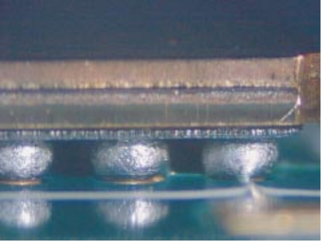
Acceptability for Electronic Assemblies :Soldering Acceptability Requirements

Acceptability for Electronic Assemblies :Soldering Acceptability Requirements


Target-Class1,2,3
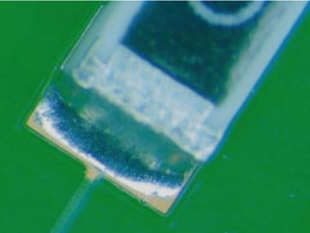
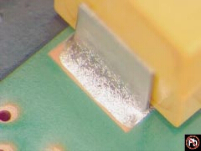
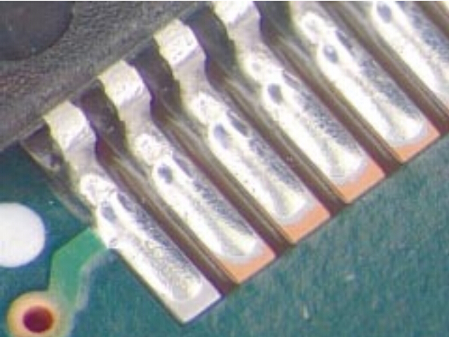
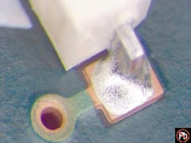
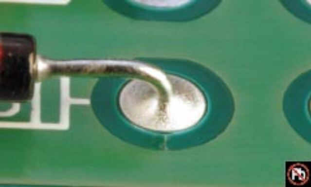
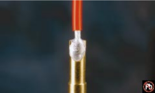
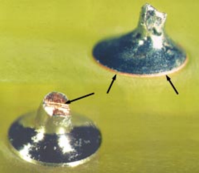
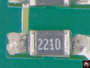
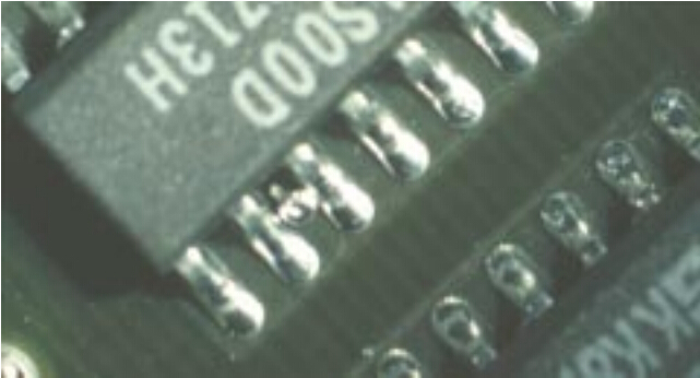
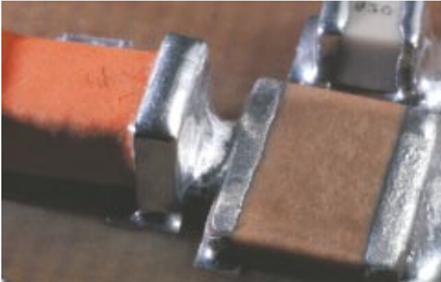
.Solder fillet appears generally smooth and exhibits good wetting of the solder to the parts being joined.
.Outline of the parts is easily determined.
.Solder at the part being joined creates a feathered edge.
.Fillet is concave in shape.


p1s1

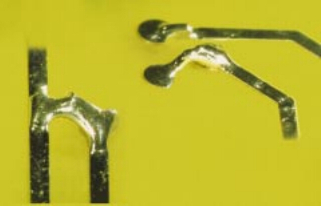
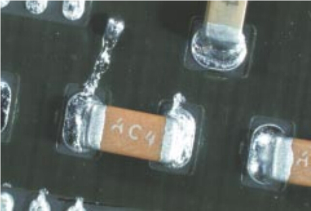
See pic for examples of soldering anomalies.

Acceptable-Class1,2,3
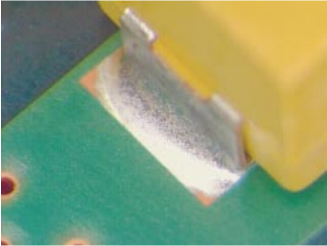
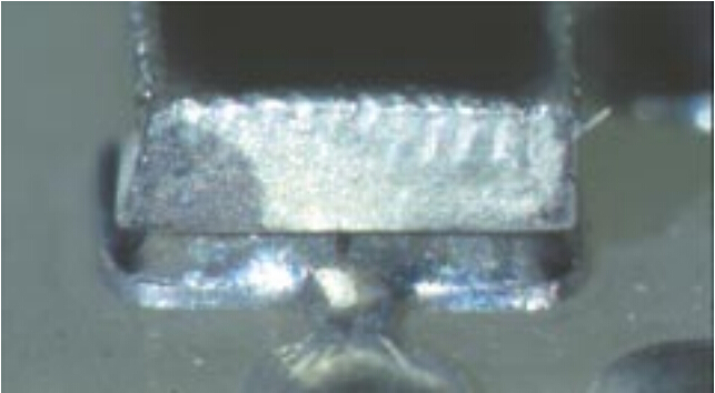
.There are materials and processes,e.g.,lead free alloys and slow cooling with large mass PCBs, that may produce dull
matte,gray,or grainy appearing solders that are normal for the material or process involved.These solder connections
are acceptable.
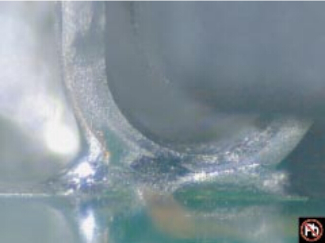
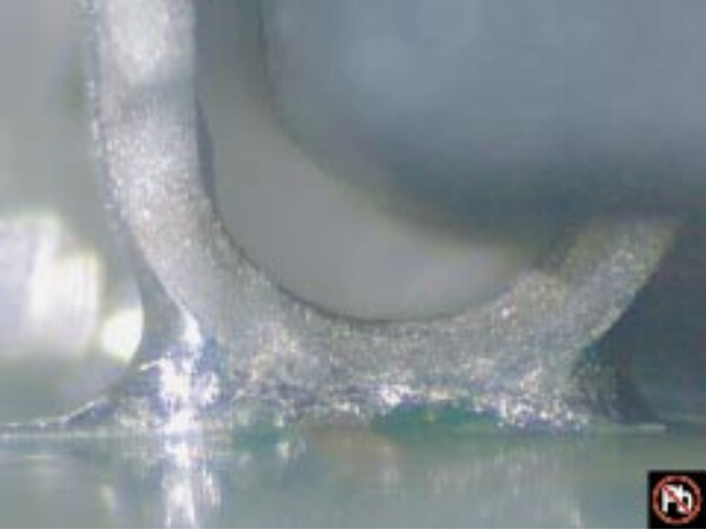
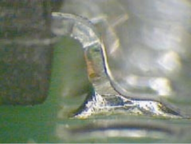
.The solder connection wetting angle (solder to component and solder to PCB termination do not exceed 90°(Figure).
.As an exception,the solder connection to a termination may exhibit a wetting angle exceeding 90°(Figure)when it is 

created by the solder contour extending over the edge of the solder able termination area or solder resist.


p1s2


Figures below illustrate acceptable solder connections with various solder alloys and process conditions.

p2s1 p2s2

SnPb Solder; No Clean Process                                     SnAgCu Solder;No Clean Process

p2s3 p2s4

    SnPb Solder;Water Soluble Flux                                 SnAgCu Solder;Water Soluble Flux

p2s5 p2s6

   SnPb Solder; Water Soluble Flux                                 SnAgCu Solder;Water Soluble Flux

p3s1 p3s2

     SnAgCu Solder;No Clean Process,N2 Reflow                 SnAgCu Solder,No Clean Process;Air Reflow

p3s3 p3s4

      SnPb Solder;No Clean Process                                  SnAgCu Solder;No Clean Process

p3s5 p3s6

     SnPb Solder;No Clean Process                                   SnAgCu Solder;No Clean Process

p4s1 p4s2

                        SnPb Solder                                                      SnAgCu Solder

p4s3 p4s4

                     SnPb Solder                                                           SnAgCu Solder

p4s5 p4s6

         SnPb Solder ; OSP Finish                                                       SnAgCu Solder; OSP Finish

p5s1 p5s2

                     SnAg CuSolder                                                      SnAg CuSolder

p5s3 p5s4

                 SnAgCu  Solder                                                         SnAgCu Solder


       Soldering Anomalies-Exposed Basis Metal

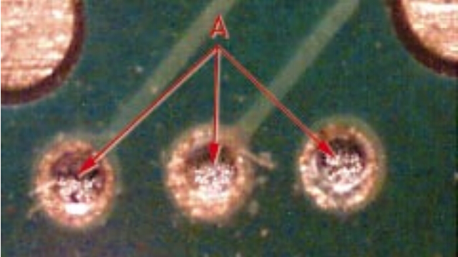
Exposed basis metal on component leads,conductors or land surfaces from nicks,scratches,or other conditions cannot exceed
there quirements of 7.1.2.3 for leads and 10.2.9.1 for conductors and      lands.
Component leads,sides of land patterns,conductors,and use of liquid photo image able solder resist,can have exposed basis
metal per original designs.
Some printed circuit board and conductor finishes have different wetting characteristics and may exhibit solder wetting only to
specific areas. Exposed basis metal or surface finishes should be considered normal under these circumstances,provided the
achieved wetting characteristics of the solder connection areas are acceptable.


Acceptable-Class 1,2,3
.Exposed basis metal on:
.Vertical conductor edges.
.Cut ends of component leads or wires.
.Organic Solderability Preservative (OSP) coated lands.
.Exposed surface finishes that are not part of the required solder fillet  area.

p6s1 p7s1


Acceptable-Class 1

Process Indicator-Class 2,3

.Exposed basis metal on component leads,conductors or land surfaces from nicks or scratches provided conditions

do not exceed the requirements of7.1.2.3 for leads and 10.2.9.1 for conductors and lands.

p7s2


 Soldering Anomalies-Pin Holes/Blow Holes


Acceptable-Class1
ProcessIndicator-Class2,3

.Blowholes (Figures 1,2),pinholes (Figure 3),voids (Figures 4,5),etc.,providing the solder connection meets all other requirements.


p8s1 p8s2                           

                          1                                                                                2                                                                        

p8s3 p8s4

                             3                                                                                 4

 p8s5                     

                                  5

Defect-Class 2,3

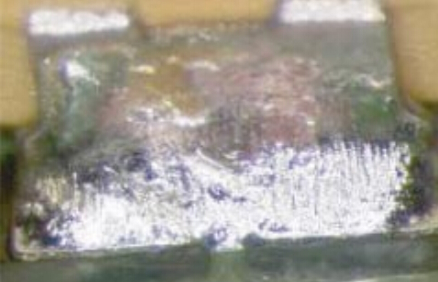
Solder connections where pin holes,blowholes,voids,etc.
reduce the connections below minimum requirements(not shown).


Soldering Anomalies-Reflow of Solder Paste

 Defect-Class1,2,3
.Incomplete reflow of solder paste.


p9s1

 p9s2


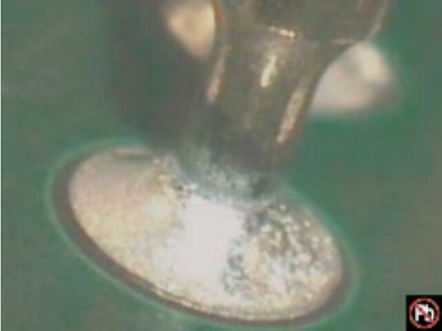
Soldering Anomalies-Nonwetting

IPC-T-50 defines nonwetting as the inability of molten solder to form a metallic bond with the basis metal.In this Standard,that
includes surface finishes.

Defect-Class 1,2,3
.Solder has not wetted to the land or termination where solder is required.
.Solder coverage does not meet requirements for this termination type.

p10s1

p10s2

p10s3

p10s4

p10s5


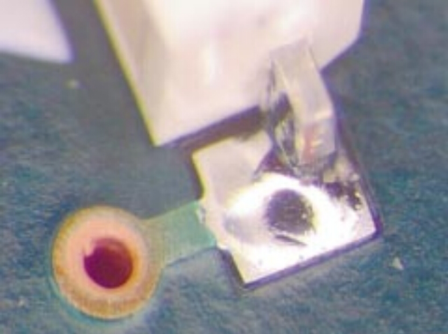
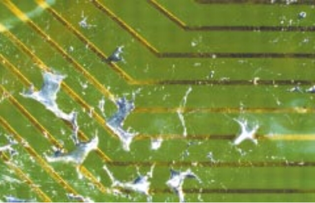
Soldering Anomalies-Dewetting

Defect-Class 1,2,3
.Evidence of dewetting that causes the solder connection to not meet the SMT and thru-hole solder fillet requirements.


p11s1

p11s2

p11s3


                          Soldering Anomalies-Excess Solder-Solder Balls/Solder Fines

Solder balls are spheres of solder that remain after the soldering process.Solder fines are typically small balls of the original 

solder paste metal screen size that have splattered around the connection during there flow process.


Target-Class 1,2, 3
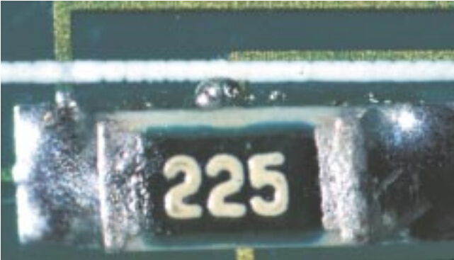
.No evidence of solder balls on the printed wiring assembly.

p12s1

Acceptable-Class 1,2,3
.Solder balls are entrapped/encapsulated and do not violate minimum electrical clearance.
 Note:Entrapped/encapsulated/attached is intended to mean that normal service environment of the product will not cause a solder ball to become dislodged.

p12s2


Defect- Class 1,2,3
.Solder balls violate minimum electrical clearance.
.Solder balls are not entrapped in no-clean residue or encapsulated with conformal coating,

or not attached(soldered)to a metal surface.

p13s1

p13s2

p13s3

p13s4


Soldering Anomalies-Excess Solder-Bridging


Defect-Class 1,2,3
.A solder connection across conductors that should not be joined.
.Solder has bridged to adjacent noncommon conductoror component.

p14s1

p14s2

p14s3

p14s4


Soldering Anomalies-Excess Solder-Solder Webbing/Splashes

Defect-Class 1,2,3
.Solder splashes/webbing.


p15s1

p15s2


Soldering Anomalies-Disturbed Solder

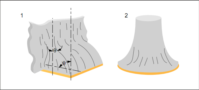
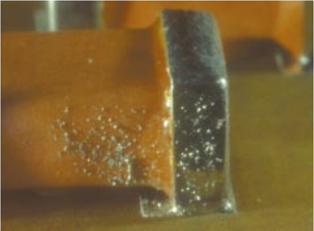
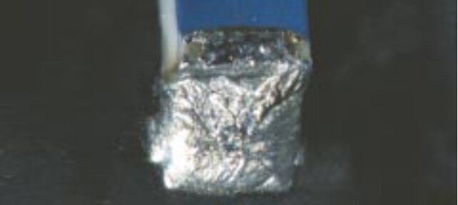
Surface appearance with cooling lines as shown in Acceptable pic is more likely to occur in lead free alloys and is not a disturbed solder condition.

p16s1


Defect-Class 1,2,3
Characterized by stress lines from movement in the connection (SnPb alloy).

p16s2

p16s3

p16s4

p16s5


Soldering Anomalies-Fractured Solder


Defect-Class 1,2,3
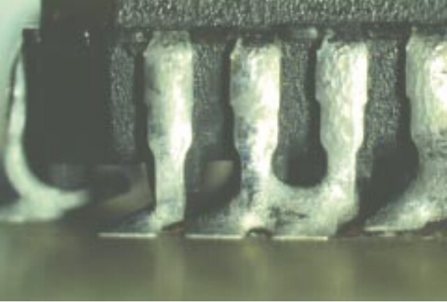
Fractured or cracked solder.


p17s1

p17s2


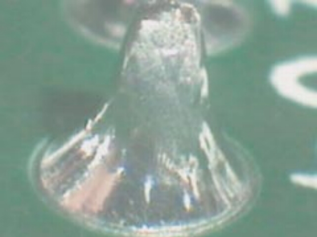
Soldering Anomalies-Solder Projections

Defect-Class 1,2,3
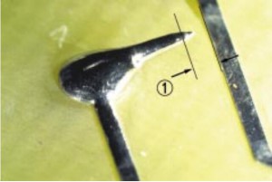
.Solder projection,figure 1,violates assembly maximum
height requirements or lead protrusion requirements.
.Projection,figure 2,violates minimum electrical clearance(1).


p18s1 p18s2

                       1                                                              2


p18s3


Soldering Anomalies-Lead Free Fillet Lift

Acceptable-Class 1,2.3
.Fillet lifting-separation of the bottom of the solder and the
top of the land(primary side of plated-through hold connection).

Process Indicator-Class 2
Defect-Class3

.Fillet lifting-separation of the bottom of the solder and the top of the land(secondary side of plated-through hold connection)(not shown).
Defect-Class 1,2,3
.Fillet lifting damages the land attachment.

p19s1


Soldering Anomalies-Hot Tear/Shrink Hole

Acceptable-Class1,2,3
.For connections made with lead free alloys:
.The bottom of the tear is visible.
.The tear or shrink hole does not contact the lead,land or
barrel wall.


Defect-Class 1,2,3
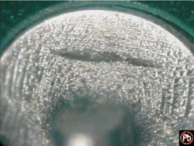
.Shrink holes or hot tear in connections made with SnPb  
solder alloys:

.For connections made with lead free alloys:
.The bottom of the shrink hole or hot tear is not visible.
.The tear or shrink hole contacts the lead or land.

p20s1

                                   end

FREQUENTLY ASKED S-K100 High Speed LED PICK & PLACE MACHINE QUESTIONS AND ANSWERS

1)What is high speed led tube and led strip pick and place machine ?

The high speed automatic SMT mounting machine is the equipment used to realize high-speed, high accuracy completely automatic mounting the electric elements like LED light sphere, electric resistance , electric capacity etc. It is the mot essential and most complex equipment in the entire SMT production. The mounting machine is the major machine in SMT production line, and it is already developed from the early low speed mechanical mounting machine to high-speed optics mounting machine, and to multipurpose, flexible connection modulation development.


2)What machines does the LED PCB board assembly need ?

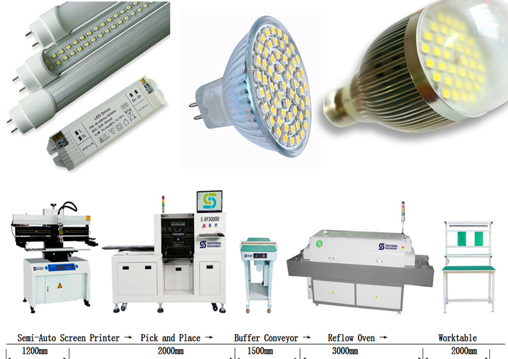
The LED mount technical process simplification is: Printing, Pick and placing, Soldering, Overhaul (in each part, you can join examine link to control quality)


3) What are the advantages of Langke smd pick and place machine?

A.Top high speed in the world, quicker than the main SMT pick and place machines brands like Siemens, Fuji, Samsung, Panasonic, Sanyo and Juki led pcb pick and place machines;

B.Lowest power consumption, 2.5-3.5KW/Hour, our machine has the smallest electricity consumption among the high speed pcb pick and place machine manufacturers in China

C.Match vacuum pumps along with the main machine, no need to match extra vacuum pump;

D.Electric control system is installed on the top of the main machine, easy to maintain, and has a good damp proof effect;

E.Integrated forming steel frame, guarantee stable performance on high speed running conditions.

F.The distance of sucking mouth can be adjusted manually, photoelectric will make sure the accuracy after adjust, allow you to mount different pitches PCB board.


4) What kinds electric components can use our automatic led smt pick and place assembling machine!

The main elements our machine can mount include: LED lights, electric capacity and electric resistance, sizes like: 0805,1206,2121,2835,3014,3528,5050,5630,5730,RGB; mainly for 1.2-1.5 meter LED light tube, LED panel light, 0.5-1.0 meter LED light strip , RGB strip.

Features & Benefits of Universal’s Axial Insertion machine — VCD/Sequencer 8

Feature

Benefit

High performance Positive Axis Control servo-drive system

Dynamic motion control for smoother,  faster,  more precise motion, yielding precise component insertion and clinching with less mechanical wear and noise.  PAC provides very high repeatability.

Insertion Head

The insertion head is direct servo-driven, with a robust and highly reliable rack-and-pinion drive. 

The rack and pinion coupled with the direct drive provide long life and precise positional accuracy, resulting in high cycle rates, greater insertion process control, and lower PPM, with less noise and wear.

Minimized manual set-ups and adjustments

Elimination of manual set-ups reduces downtime.  To ensure consistency, set-ups are now performed through IM UPS Diagnostics software.  

Insertion Tooling

Newly designed tooling has a significantly longer life –up to five times longer than the previous model.

Tooling has to be replaced less often, reducing down time, tooling inventory and cost.

Tooling uses carbide inserts and titanium nitride coating.

This extends the tooling life.

The new design better handles bent input component leads.

The robust design reduces machine interruptions & down time caused by bent input component leads.

Four tooling options are available:

5mm: insertion spans from 5mm (0.197”) to 21.59mm 

( 0.85”)

5.5mm: insertion spans from 5.5mm(0.217”) to 24.13mm (0.95”)

Standard: Insertion spans from 7.62mm (0.3”) to 24.13mm (0.95”)

Large Lead: insertion spans from 7.62mm (0.3”) to 23.88mm (0.94”)

These options satisfy most applications.  If you are unsure which tooling to choose, contact the Product Team

Centering System

New cam-actuated component centering system is driven by the insertion head motor

The new design significantly increases reliability.

The centering door has been eliminated.

Better visibility and accessibility to the insertion area.

Adjustments have been reduced by 50%.

Only five simple adjustments are required on the centering system, reducing maintenance time.

The new centering system is a simple design, with 50% part reduction over the previous model.

The design provides increased reliability and extended life, with significantly less maintenance.

The centering fingers have replaceable carbide inserts

The inserts keep costs down and reduce maintenance cost and time. 

Servo-Driven Cut and Clinch

The clinch is operated with a servo-driven rocker/slide mechanism.

This mechanism provides quiet and repeatable up/down operation, increasing reliability and reducing maintenance.

The servo-driven anvil mechanism operates in a two-step motion.  The lower position is used for table rotation and board transfer, while the mid-position to full up-position is used for cutting and clinching component leads.  

The two step motion reduces motion cycle time and increases operating life.

Right and left anvils are coupled.

The coupled anvils assure synchronous operation and simplify set-ups. 

Anvil height set-up is performed via IM diagnostics software.

Guesswork is eliminated.  The anvil height is consistently set to program dimensions through the software, for greater accuracy and precision.

All mechanical adjustments are in the front and on the top of the clinch base.

The adjustments are in easy-to-reach locations, making them quicker and easier to perform.

The clinch assembly is pinned to the frame.

Head alignment after clinch removal and replacement is eliminated.

The clinch cutters use the proven Universal pneumatic actuators.

The actuators assure a full range of operation on leads from 0.38mm (0.015”) to 0.81mm (0.032”).

Positioning System

The positioning system operates by new X-Y motors with tachometer feedback and more responsive servo amplifiers.

7.62mm (0.30”) table moves are possible with no effect on machine cycle rate.

The table motion is smoother and more controlled.

Improved table motion increases the life of mechanical parts.

Insertion Span Axis

The insertion span axis uses a direct drive system with a brushless DC servo motor.

This drive eliminates belts, external motors, and limit switches, for greater reliability and less maintenance, while providing more precise positioning.

Chain-to-Chain Transfer

The new scrap remover is mechanical.

The design is a passive mechanical device that is quiet, clean and reliable.

The sequencer chain drive is operated by a new brushless servo motor.

The drive gives more precise dynamic position control for improved component transfer, lowering PPM.

Board Error Correction (BEC) and “Teach”

BEC is a four quadrant electro-optical sensor, used to measure expected programmed PCB hole locations.  It provides feedback to the control processor to compensate for PCB hole misalignment, which drives the X-Y table to the desired hole location.

BEC adjusts a given pattern to a given board, significantly lowering PPM.  BEC compensate for circuit board construction variations between tooling holes and related patterns, improving insertion reliability.

“Teach”uses BEC to custom fit a pattern to a board.

“Teach”greatly improves pattern accuracy and lowers PPM. 

Add – On Sequencer Modules

The sequencer is available with up to 220 stations (in 20-station add-on modules).

The add-on modules provide flexibility in meeting a variety of applications.

Improved “Low Part’warning is displayed on the machine monitor, which indicates the module and level of the “low part”condition.

“Low Part”warning is more visible to the operator, defining the location better.  The warning is recorded, for better process control.

The dispense head guides and bearings are newly designed.

The new design improves reliability and ease of use.

The pneumatic valves are DC.

DC valve provide improved response for more consistent dispense head actuation.

Refire

Optical refire senses missing parts in the component input tape.

Refire reduces “Part Missing”errors by actuating the dispense head if a part is not sensed in the component input tape.

Easy-to-see LEDs show dispense head refire status.

The LED’s simplify input component loading by visibly displaying refire status and input component sensing in the dispense head.

Refire information is fed back to the machine controller

The feedback provides better information for machine performance analysis.

Jumper Wire Dispense System

Up to two jumper wire dispensers may be used in the machine.  Jumper wire dispensers may be placed on stations 3 and 23.   

Even the most “jumper wire intense”applications can be satisfied with no effect to machine cycle speed.

Jumper wire dispenser design improvements:

Improved wire feeder alignment

New drive bearing

The new design gives better cut length accuracy and increased wire dispense reliability, longer bearing life.

System Software

The VCD/Sequencer 8 utilizes IM-Universal Platform Software (IM-UPS)

This is the same Windows-based software used in Universal’s other through hole Series 8 machines and surface mount equipment, reducing the learning curve for operation, maintenance, and programming.

Graphical user interface with “pop-up”error screens

Easy to understand and use, especially for non-English speakers.

Advanced Product Editor (APE) offers a component library, graphical display of PC board, and insertion path.

APE makes programming quick, accurate, and easy.

Optimization feature

Optimization improves programs by ordering steps in the fastest insertion path.

Management data is generated & stored in a database

Machine performance can be tracked and graphed to provide a quick aid for decision making and reporting. 

Machine event messages are displayed and logged.

Machine activity can be traced, greatly aiding analysis.

Diagnostics are provided on-line

The diagnostics through software provide point-and-click simplicity for set-up and sub-system troubleshooting.

On-line manuals and user help is provided

Eliminates the need to keep manuals near the machine

Product trainer

Available in English, Spanish, and Chinese, Product Trainer provides operating and maintenance instructions through a CD.  This tool increases workforce competency and productivity  

Repair

The operator clears any misinserted component, and places a new component in the repair location.  If the ERV option is present, the machine verifies the correct part, inserts it, and clinches it automatically.

The “repair”mode enables outgoing board quality to reach 0 PPM.

Expanded Range Verifier (ERV) –Option

ERV provides on-line verification of component values and polarity.

ERV reduces the possibility of inserting defective, out-of-sequence, or incorrectly oriented components in the pattern location.

Other Features

Uninterruptable Power Supply

In the event of a blackout or brown out, the UPS provides up to 10 minutes of power.  This allows the operator to save patterns and end the current cycle.

Audible alarm

The audible alarm is programmable to alert operators of machine conditions. 

HIGH SPEED DISPENSING OF SURFACE MOUNT ADHESIVE BETWEEN SOLDER PASTED PADS

HIGH SPEED DISPENSING OF SURFACE MOUNT ADHESIVE BETWEEN SOLDER PASTED PADS


Introduction


Surface mount
adhesive has been a part of electronics manufacturing applications from
the beginning of SMT. It has been used, in conjunction with wave
soldering processes, to successfully solder millions of components to
the bottom sides of printed circuit boards. In an effort to make the
manufacturing processes more robust and to improve the quality of the
assemblies, a solder paste printing step and a reflow soldering step
have been added to many traditional bottom side assembly lines. These
operations are added in order to decrease defects such as missing
components and insufficient solder joints. Both SMT (double sided
reflow) and Through hole (mixed SMT/THT) processes can benefit from this
process utilizing adhesive and solder paste. Some of the process
considerations are nozzle design, pad design, PCB layout, stencil
design, and adhesive properties. This article will deal with the
characteristics that must be considered in setting up this process, how
it can be implemented successfully, and typical line configurations
associated with this process. The major foundation of traditional
bottom side assembly processes is the adhesive.


Adhesive Selection


 When selecting an
adhesive for applications involving the dispensing of surface mount
adhesives between solder pasted pads, it is important to choose an
adhesive that is formulated to give very specific rheological, or flow
properties. The adhesive selected should be formulated to allow for a
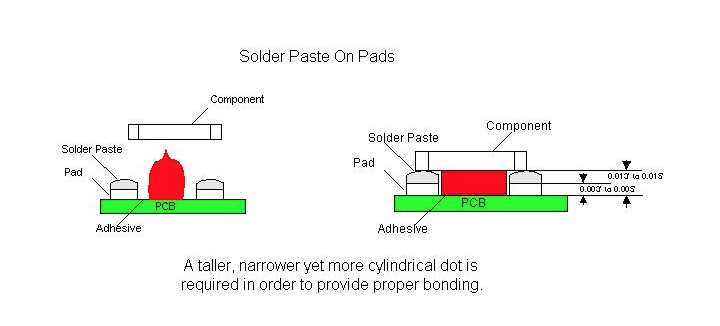
higher profile dot that exhibits very little slump. This will allow the
glue to contact the component, above the height of the solder paste
deposition, when the component is placed. Dots dispensed for this type
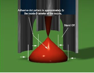
of application should have a tall, cylindrical shape as opposed to the
typical triangular Hershey kiss dot profile. The typical profile may
not allow the glue to properly adhere to the component prior to curing
and then hold the component through wave soldering. This will cause a
large number of missing component errors to be seen following the wave
soldering operation. Excessive missing components following manual
assembly may also be seen because the glue joint is not large enough to
provide the strength needed to hold the components in place.

 The surface mount
adhesive chosen for these applications must also have a high green
strength in order to hold the component prior to the curing process. It
is this green strength that also helps the adhesive to maintain the
tall cylindrical dot shape needed when dispensing between solder pasted
pads. Without it the adhesive deposit will slump, losing contact area
with the component, and causing a decrease in the strength of the
adhesive joints.

SMT,THT,PCB,PCBA,AI,wave soldering,reflow oven,nozzle,feeder,wave soldering,PCB Assembly, LED, LED lamp, LED display,


 In adhesive
dispensing processes utilizing heat, it is difficult to achieve the
necessary dot height. By applying heat to the adhesive, the material’s
viscosity is lowered, allowing it to flow more easily. This type of
flow characteristic will cause the adhesive dot to slump after
dispensing. Problems related to the adhesive not contacting the
component (missing components after wave soldering, etc.) will increase
in frequency, as well as the number of opportunities for defects such as
pad contamination to occur.


Board Design

SMT,THT,PCB,PCBA,AI,wave soldering,reflow oven,nozzle,feeder,wave soldering,PCB Assembly, LED, LED lamp, LED display,


 Typically,
surface mount component pads are designed for either adhesive deposition
or the screening of solderpaste. The pad spacing is generally smaller
for solderpaste application as opposed to that of adhesive deposition.
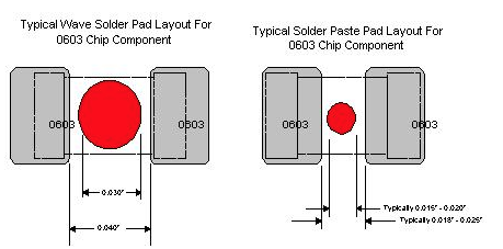
For example, the component pad spacing between the pads of a 0603 chip
cap/resistor is typically 0.020”, if the board was designed to be screen
printed with solderpaste. The pad spacing for the same board can be
0.040” if adhesive deposition was to be utilized. A 0.030” diameter dot
of adhesive would easily be recommended for use if the component pads
on the board were indeed designed for adhesive deposition. However, if
the pad design for the same board was originally designed for
utilization of solderpaste, as a method of adhering the component to the
board, obviously, an 0.030” diameter dot of adhesive would be too
large, as the spacing between the pads is now 0.020”. A 0.015” to 0.018”
diameter dot is required for this particular application.

 In designing pad
spacing and component spacing, the height of the pad and the solder
paste deposition must also be taken into consideration. Typically, the
height of an adhesive dot is one half the diameter of the dot.
Depending upon the material used for the pads, it would be possible
design a board which would be impossible to print and dispense adhesive
on. If the typical dot size for a 0603 component were 0.015” to 0.018”,
the height would be approximately 0.0075” to 0.009”. If the thickness
of the stencil utilized to print the solder paste was 0.006” to 0.007”
this might not allow the glue dot to contact the component body on some
types of board finishes. For example, a typical HASL finish is
approximately 0.003” thick. If the thickness of the stencil utilized
were 0.007”, the adhesive dot would have to be at least 0.011” to 0.012”
tall to properly contact the component. This would require
approximately a 0.022” diameter dot. This is why the rheology of the
adhesive is so important. If the adhesive slumps at all after
dispensing, it may not properly contact the component. The nozzle
design also plays a part in the development of the correct dot for each
application.


Nozzle Design


When selecting a nozzle for use in dispensing adhesives the main characteristics that must be considered are nozzle
design, standoff size and placement, and nozzle ID. A relationship
exists between these characteristics and the adhesive dot diameter.
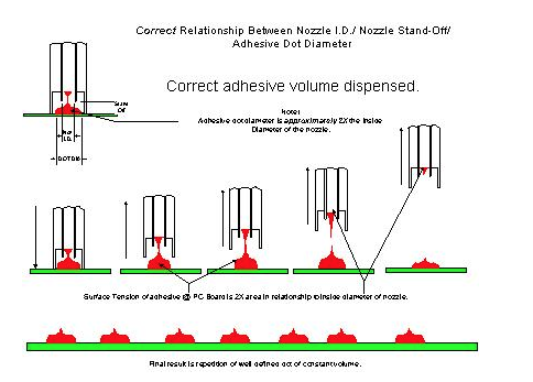
When the adhesive volume is dispensed, the surface tension of the
adhesive on the board, should be twice that of the surface area of the
adhesive at the nozzle tip. If this condition exists, as the nozzle
retracts, the adhesive will snap off clean from the nozzle and leave a
well-defined dot of constant volume on the board. The nozzle must be
chosen based upon the size dot that is required by the application.

SMT,THT,PCB,PCBA,AI,wave soldering,reflow oven,nozzle,feeder,wave soldering,PCB Assembly, LED, LED lamp, LED display,


Nozzle selection
refers in this case to specific nozzle specifications for a known dot
size requirement. The dot size requirements can be derived from the
board design being utilized or specifically the pad spacing of
components. Reference pad spacing previously discussed in this paper. It
is not uncommon for Manufacturing Engineer personnel or Quality
Engineering personnel of a printed circuit board manufacturing facility,
to inquire what a recommended adhesive dot diameter should be for a
particular component type. Much has been written in regards to
recommended surface mount component pad designs and layouts for bottom
side applications. Topside pad designs are also used on bottom side PCB
fabrication. However these guidelines are rarely utilized. The pad
spacing for a particular component for each individual customer product
is unique.

Because the pad
spacing for most typical surface mount components is not standardized
from one customer product to another, it becomes a challenging task when
recommending what tooling should be utilized to satisfy a particular
customers’ adhesive deposition requirement for a particular component.

Note that the
volume of adhesive needed to maintain the component in place during the
high speed placement or wave solder process may be larger than possible
for some specific pad designs.

The nozzle standoff
can be defined as the distance from the tip of the dispensing surface
to the end of the mechanical standoff. The nozzle standoff is used to
maintain the distance between the PCB and the dispensing tip. Most
dispensers in use today are designed to utilize some sort of mechanical
standoff with the nozzles. The standoff usually dictates, to some
degree, the height of the dispensed dot

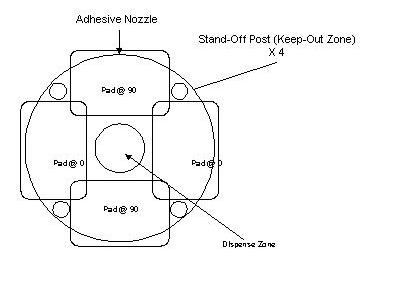
Typical designs for
nozzle standoffs are the castle design, the post design, or a dual post
design. For applications utilizing surface mount adhesive between pads
that have had solder paste applied to them, a single post design nozzle
is the most appropriate. In this type of application the standoff
should be set at 45
° , 135 ° , 215 ° , or 315 ° around the pad circuitry.

SMT,THT,PCB,PCBA,AI,wave soldering,reflow oven,nozzle,feeder,wave soldering,PCB Assembly, LED, LED lamp, LED display, 


When selecting the
correct nozzle ID a rule of thumb is that the nozzle ID should be one
half of the required dot diameter. This will allow for the correct dot
diameter to be dispensed so that the glue snaps away from the nozzle
without contamination. By beginning with this guideline, the
approximate nozzle diameter can be determined, and then adjusted based
upon the material utilized.

SMT,THT,PCB,PCBA,AI,wave soldering,reflow oven,nozzle,feeder,wave soldering,PCB Assembly, LED, LED lamp, LED display,


Stencil Printing Considerations


 When printing
solder paste prior to dispensing surface mount adhesive, there are some
stencil design considerations that must be taken into account. The
thickness of the stencil is important because it will determine the
height of the solder paste depositions. This also determines the
minimum height of the dot that must be dispensed in order to properly
contact and hold the component. In applications where wave soldering
will follow manual assembly, a smaller stencil thickness may be used
because the ultimate solder joint quality will be determined by the wave
soldering operation. It may also be beneficial, on pads with very
tight pads spacing, to undercut the stencil so that as much space as
possible is available for adhesive deposition.


Adhesive Curing


    When printing
solder paste and dispensing epoxy between solder pasted pads a
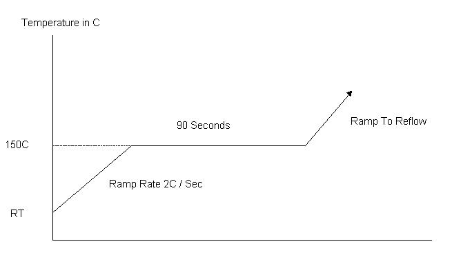
specialized cure cycle is required. Curing epoxy at 150º C is a
bondline temperature that should be verified with thermocouples at
various locations. Curing epoxy at temperatures above 160º C can cause
the adhesive to become brittle, leading to possible component loss
during the solder wave process. The solution for this is that the epoxy
must be cured at 150º C for about 90 seconds prior to ramping to the
reflow temp. This type of reflow takes into account the adhesive cure
as well as the solder paste reflow. Care should be taken to check the
quality of the solder joints achieved with this profile. The graph
below is a sample of what the cure cycle should look like. The final
profile should take into account the recommended profiles from both the
adhesive and from the solder paste manufacturers.


SMT,THT,PCB,PCBA,AI,wave soldering,reflow oven,nozzle,feeder,wave soldering,PCB Assembly, LED, LED lamp, LED display,


Placement Machine Considerations


 When selecting a
placement machine for use in a process utilizing the dispensing of
surface mount adhesives between solder pasted pads, it is important to
consider the accuracy and the repeatability of the placement machine
down line. In typical top side applications utilizing solder paste
printing, when the solder paste is reflowed, the forces associated with
the solder, automatically center the component, within reason, on its
pads. When glue is added to the process this does not occur because the
glue resists these forces since it is cured prior to the reflowing of
the solder paste. It is important to consider all of the machines in
the line when developing this type of process.


Typical Manufacturing Line Configurations


Traditional Bottom Side Line

SMT,THT,PCB,PCBA,AI,wave soldering,reflow oven,nozzle,feeder,wave soldering,PCB Assembly, LED, LED lamp, LED display,

  GDM Adhesive Dispenser

  Vitronics Reflow Oven

  HSP Chipshooter


Typically, a
traditional bottom side manufacturing line includes an adhesive
dispenser, a chipshooter to place the bottom side components, and an
oven to cure the adhesive. This line will be followed by a wave solder
machine, which will in turn be followed by an inspection and/or rework
station.

The first thing
that must be considered when setting up any manufacturing line is the
type of components and assemblies that are going to be used or built on
it. A traditional bottom side line can be used simply to apply glue to a
printed circuit board, place components on the board, and then cure the
glue in order to hold the parts onto the board prior and during wave
soldering and manual assembly. In this type of application the green
strength of the material determines whether components stay in place
during placement operation on the chipshooter. The post cure strength
of the adhesive determines whether or not the components will stay on
the board during manual assembly and handling. This makes the choice of
glue very important. After wave solder, using this type of line, parts
may be missing due to missing or unacceptable adhesive dots or some may
have be knocked off the board during manual assembly or handling. Care
should be taken to control the forces that these assemblies are
subjected to. This line is very basic in its functionality but can
reliably build products when implemented correctly.


Bottom Side Line With Solder Paste Application

SMT,THT,PCB,PCBA,AI,wave soldering,reflow oven,nozzle,feeder,wave soldering,PCB Assembly, LED, LED lamp, LED display,


  HSP Chipshooter

  DEK Stencil Printer

  Vitronics Reflow Oven

  GDM Adhesive Dispenser


A bottom side line,
that includes solder paste application, incorporates a system for
applying the solder paste (stencil printer or high speed dispenser), an
adhesive dispenser, a chipshooter for the bottom side components, and an
oven to cure the adhesive and reflow the solder paste. A wave solder
machine and an inspection and/or rework station will then follow this
line.

This type of
manufacturing line is more flexible than the previously discussed line.
For bottom side applications, this configuration provides greater torque
strength due to the adhesive being combined with solder paste. This
will assist in reducing the number of missing part defects present in
the assembly. This type of line also helps to reduce problems related
to the wave soldering operation (insufficient solder). In this type of
application, the dot height is important to consider because the dot
must be tall enough to contact the component even above the solder paste
deposit. Consideration also must be given to the design of the stencil
used to print the solder paste and the design of the nozzle used for
high speed dispensing operations. Both of these points can turn into
problems later if not considered properly.


Mixed Technology Top/Bottom Assembly with Solder Paste Application

 SMT,THT,PCB,PCBA,AI,wave soldering,reflow oven,nozzle,feeder,wave soldering,PCB Assembly, LED, LED lamp, LED display,

      Vitronics Reflow Oven

  HSP Chipshooter

  GDM Adhesive Dispenser

  DEK Stencil Printer

  GSM Flexible Placement


A mixed technology
line for assembling top and bottom side products includes a system for
applying the solder paste (stencil printer or high speed dispenser), an
adhesive dispenser, a chipshooter to place the bottom side components, a
flexible placement machine to place top and bottom side components, and
an oven to cure the adhesive and reflow the solder paste. A wave
solder machine and an inspection station will then follow this line.
The inspection station however, should see limited use because of the
robustness of this process.

This manufacturing
line is more flexible than either of the previously discussed lines.
Like the bottom side manufacturing line with solder paste, on bottom
side applications, this configuration provides greater torque strength
due to the adhesive being combined with solder paste. This assists in
reducing the number of missing parts present in the assembly. This
also helps to reduce problems related to the wave soldering operation
(insufficient solder). In this type of application, the dot height is
important to consider because the dot must be tall enough to contact the
component over and above the solder paste deposit. Consideration also
must be given to the design of the stencil used to print the solder
paste and the design of the nozzle used for high speed dispensing
operations. This line also can be used for topside applications
including the deposition of solder paste, chip placement and flexible
placement (QFPs and BGAs for example). This type of flexible
manufacturing line has become the choice for contract electronics
manufacturers because it offers a simple, total assembly solution.


Conclusion


 The dispensing of
surface mount adhesives has been a part of electronics manufacturing
since the development of surface mount components. In an effort to make
the processes involved more robust, solder paste has been added to many
manufacturing line configurations. This configuration helps to
eliminate defects such as missing components and insufficient solder
joints following wave soldering.

 In order to
implement this process there are a lot of considerations that must be
taken into account. The type of adhesive used must have rheological
properties that allow for a tall, cylindrical dot versus the typical
Hershey kiss shaped dot. This type of dot is required to properly
adhere to the component when it is placed on top of the solder paste
deposits. In order to obtain the correct dot height, the board design
must be considered carefully. By designing in the correct pad spacing,
implementation of this process is much simpler. The volume of solder
paste required must then be determined as well as the design of the
stencil. The required adhesive dot size must be considered when
designing the stencil. After the board is designed and the volume of
solder paste required has been determined, a nozzle must be designed to
provide the correct dot diameter with standoffs that will not become
contaminated with solder paste. After the adhesive is deposited and the
chips have been placed, the glue must be cured and the solder paste
must be reflowed. The profile used for this process must be developed
from the adhesive and the solder paste manufacturers’ recommended
profiles. Finally, the type of assemblies that are going to be built
must be considered when developing a manufacturing line that will meet
your needs now and in the future.

 By carefully
considering all aspects of your manufacturing process, the dispensing of
surface mount adhesives between solder pasted pads can help eliminate
defects associated with typical electronics manufacturing processes.
This process helps to eliminate problems such as insufficient solder
joints. In applications where only glue was previously utilized, this
type of process can help eliminate defects such as missing components,
that can occur as a result of handling and manual assembly. By taking
time to consider the characteristics of your manufacturing process, the
correct line configuration and process parameters can be developed to
build the highest quality assemblies possible.


How to evaluate SMT Auto Insertion machine supplier

Quality System Assessment Summary Report

Supplier:  

Commodity Team:

Primary Audit Contact:

Address:     


Supplier Commodity/Product Specialty:

Audit Team:


Phone: 


Fax: 


Elements


Max.

Audit Date:

Re-audit Date:

/ /

%

Improvement


Physical/ Logistical

Capabilities

(for information only)

Score

(0-3)


Score

Score

Score


A. Geographic location

3

1 Management Responsibility


B. Plant condition / size

3

2 Quality System


C. Employment / labor recruiting

2

3 Contract Review


D. Finance resources

3

4 Design Control


E. Pricing history

2

5 Document and Data Control


F.   Equip. Condition /age / application


2

6      Purchasing and verification


G. Backlog / capacity status

2

7 Customer Supplied Products


Yes/ No for following

8 Product Identification and Traceability

4


H. ISO / QS 9000 certified

Yes

9 Process Control


I. Design Capability

Yes

10 Inspection and Testing


J. Quick turn/prototype capability

Yes

11    Control of Inspection and Test Equip.


12


K. JIT capability / Kanban

Yes

12 Inspection and Test Status

2


13 Control of Nonconforming Product


14 Corrective and Preventive Action

6


Calculations:

15 Handling, Storage, Pack. and Delivery

9


1. Quality System Score (%):

16 Control of Quality Records

5


Total Audit Score x 100

17 Internal Auditing

10


(Total Max. Score – N/A Score)

18 Training

6


2. % Improvement:

19 Servicing

4


(New Score – Previous Score) x 100

20 Statistical Techniques

30


Previous Score

21 Continuous Improvements


Total Score


Auditor’s Signature:   


% Score


Date: 

Quality Control for Auto Insertion machine manufacturing


Quality Control


Every Auto Insertionl machine
is subjected to a Quality Acceptance Test (QAT) before being shipped to
its customer. There are 4 phases to a QAT:


Phase I – Pre-Dry Cycle


The
appropriate pattern program is loaded and the machine performs a short
part run with all motions and mechanisms functioning to check setups and
speed. All data is recorded on the machine’s event log.


Phase II – Dry Cycle


Can
only occur after successful completion of the Pre-Dry Cycle. The
machine is run with all motions and mechanisms functioning but without
boards or inserting components for a pre-specified period of time. All
data is recorded on the machine’s event log.


Phase III – Integrity Run (Final Run)


Can
only occur after successful completion of the Dry Cycle. This is a
simulated production run to check insertion performance and speed.
Results are recorded on the machine’s event log.


Axial Inserter

S4000

Radial Inserter

S3000

Phase I


Parts Run

2000

2000

Insertion PPM *

0

0

Intrinsic Availability **

100%

100%

Phase II


Length of Run

12 hrs.

12 hrs.

Intrinsic Availability

95%

95%

Phase III


Minimum Parts Run

20000

20000

Allowable Insert Errors

10

20

Intrinsic Availability

95%

95%

Acceptable PPM Levels

500 – 1000

1000

Confidence Level

95%

95%


* (# of good insertions / total # of insertions)

** (# of hours the machine is ready to run / total # of hours machine planned to run)


Phase IV – Customer Acceptance (Optional)


Can
only occur after successful completion of the Integrity Run. The
customer visits the factory to watch verify the machine’s ability to
meet performance requirements. The customer’s production run is
simulated and all options are verified and explained. 


 For any further questions regarding the customer acceptance procedure, please  contact:


 Albert Wen

 Albert@smthelp.net


Phase V – Preproduction Acceptance (At customer site)


Service engineer installs the machine and assures it is setup
and running with the same degree of operational efficiency as at the
factory.


Southern Machinery WARRANTY POLICY ON ALL NEW Machines

WARRANTY POLICY ON ALL NEW Machines

Southern Machinery warrants its products to be free from defects in materials and workmanship for a period of one year from completion of installation, provided the products are installed as specified by Southern Machinery, maintained by qualified service personnel and the products are operated in accordance with published operating procedures.  For purposes of the foregoing warranties the “completion of installation” shall be that date, within 90 days of shipment of Southern Machinery’s products from its factory, on which the products are installed and operating to the published specifications.  If the customer believes a product to be defective in material or workmanship, or failing to meet the specifications, the customer shall notify Southern Machinery of such alleged defect or failure.  Southern Machinery shall have a reasonable opportunity to investigate any alleged defect or failure, and upon confirmation of its existence Southern Machinery shall promptly remedy the same by repair or replacement, at its discretion and without charge.  The seller warrants parts repaired or replaced for the duration of the original warranty period.

The warranty does not apply to:

1. Consumable parts as they are defined in this document.

or

2. Defects or failures as a result of non-compliance with U Southern Machinery’s installation specifications.

or

3. The customer’s failure to perform the recommended normal maintenance, set up and the adjustment of the equipment.

or

4. The customer’s alteration / modification to the equipment without Southern Machinery’s prior written approval.

or

5. Damages to the equipment resulting from non-compliance with published operating procedures.

or

6. The use of replacement parts not supplied by Southern Machinery or Southern Machinery’s approved suppliers.

Definition of Consumable Parts (Non Warranty):

A) Machine parts that come in direct contact with component processing.

Examples are, but are not limited to, insertion head tooling, chain clips, lead cutter tooling, etc.

B) Maintenance/bulk items.

Examples are, but are not limited to, lubricants, adhesives, light bulbs, fuses, seals, o-rings, etc.

All other machine parts are warranted for 12 months from the machine in-service date, completion of installation.

Disclaimer Statement:  

The life expectancy of consumable tooling is dependent on proper preventive maintenance, proper machine set-up, and the type of component used by the customer.  A customer may experience greater life expectancy or less life expectancy depending on the above.

Auto Insertion machine Competitive Analysis – TDK AC7 vs Universal VCD

Axial Products Competitive Analysis

Competitor

Location

Key Weaknesses

Key Strengths

Comments

TDK 

(Rank 2)

Japan/U.S.

No Axial experience

No previous Axial machines in product mix, offering only a SH VCD (no Sequencer, DH, etc.)

Axial product offering is VERY similar to Dynapert V12000.  Possible patent infringements on Dynapert design.

Support infrastructure is inferior to UIC’s.

Low price machines

Field proven reliability of Radial Inserter

Large multi-national installed base for Radial Inserter

Japanese firm, thus strong JMA loyalty

Asian company, thus understands Asian business needs

Operates in Microsoft Windows interface, which provides immediate productivity feedback

Financially sound and stable

Offer a  SH VCD – Avisert AC-7

TDK Competitive Summary


AC-7 Avisert Features:

· Board offset correction

· Insertion hole correction

· Ammo or reel input packaging

· Push button control panel

· Microsoft Windows interface

· Intelligent operator message feedback

· Servo driven cam operated insertion head

· Servo motor driven rotary table

· Available Options: 

– Pass through capability

– Throughput optimizer

– Flexible work board holder

– Touch screen

  – Pattern repeat

– Multi tier security software

– Optical safety device

– Integrated machine enclosure

Key Sell Against Points:

Universal offers a complete Axial product line; Single Head, Dual Head, VCD Sequencer and Sequencers while TDK offers a single Axial machine.

Universal completes the IM product offering with Radials and Special Products which include Eyelet and Pin Inserting Machines, and 3-Span Radials.

We offer optional Universal board handling on most models.

Universal offers a superior training, service and support infrastructure.

We offer industry leading cost per insertion and the highest throughput per square foot of floor space.

UIC Strengths and Proof Points:

UIC Strengths

Benefit

For the Customer:

Machine designs allow flexibility in the production environment.

Universal offers a complete IM product line of Axial inserters, Sequencers and combination machines, as well as Radial product offerings.

Universal board handling is optional for machine integration.

Discuss customer need for  factory integration.

Possible future need for increased automation.

High value for the price, and  fastest inserters in the industry.

Dual Head machines provide  the highest throughput in the industry, 32,000 cph, a cost effective approach for high volume applications.

Ask the customer to compare cost per insertion.

Superior service, support and training.

Excellent investment protection.

UIC is a respected and secure provider of insertion equipment.

Pre and post sale assistance with specific applications and systems integration.

Ask the customer to compare UIC’s support infrastructure (tech. specialists, spare parts, FE response time) to Panasonic.  Also discuss unique value benefits – Uptime 100 and Tech Advisor.

TDK Strengths and Counter Points:

Competitor Strength

The Facts

For the Customer:

Perceived high throughput (16,000 CPH).

The throughput Nepcon Tokyo 觀appeared closer to 10,000 CPH.

Noisy.

Demonstrate UIC’s commitment to reducing customer costs by: 

1.  Comparing cost per insertion.

Single insertion head provides better stability and less maintenance and setup.

Dual head machine is the  highest throughput inserter in the industry with exceptional reliability and insertion performance.

Single head machine offers competitive cost per insertion with all the other values of UIC.

Demonstrate UIC commitment to customer support with:

1. Service and support, including PM schedules and maintenance manuals.

2. Uptime 100 program.

3. Tech Advisor.

4. Superior training program.  

Priced competitively in the 80K – 106K range.

Targeting existing Dynapert accounts where support requirements are minimal.

Demonstrate UIC’s commitment to reducing customer costs by: 

1.  Comparing cost per insertion.

Financial backing from a major IM provider.

Very similar to Dynapert V12000 machine 

Possible patent infringements on Dynapert design.

Not a complete product line, no complementary Sequencer available to date or board handling.  

May not have devoted TDK backing for service and support.

Determine if customer is will to obtain investment protection:

1. From a supplier that may not remain in business due to legal problems.

2. Has revived very old designs.

3. Discuss Broome Engineering products for low cost entry and their ability to allow trade-up. 

Appendix – Reference Accounts and Testimonials:

Account Name

Salesman to contact

Comments

AT&T Monterey, Mexico

Michael Lewis 

TDK offered AT&T accepted an all expenses paid trip to Boston to evaluate the AC-7 but still prefers the UIC Dual Head machines.