Meet the Needs of the SMT Age
Please read this user manual carefully before running

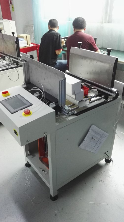
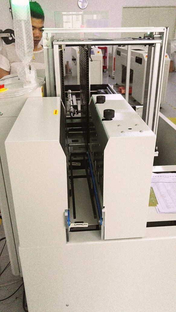
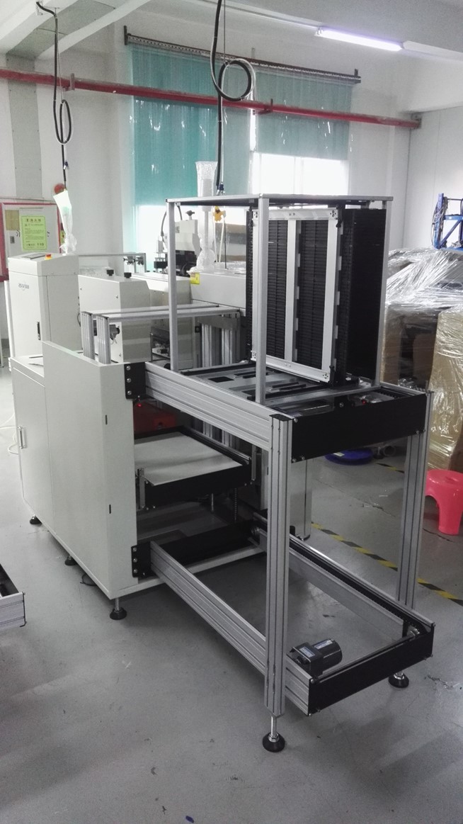
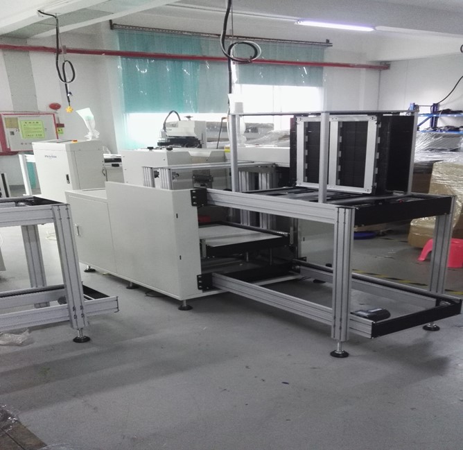
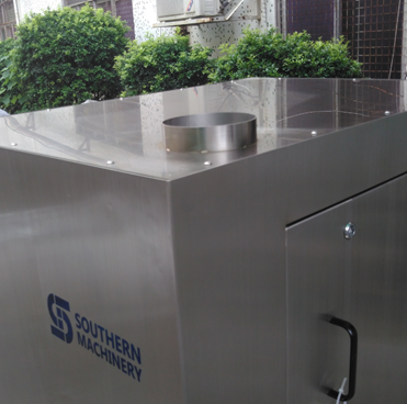
S-1688 Stencil Cleaner Machine
USER MANUAL
TEL : 0755-83203237
FAX : 0755-23240492
ADD : Room 1806, Block 3, Jinyun COFCO, Qianjin 2nd Road ,Baoan District,
Shenzhen City, China
CONTENTS
1.0 safety warning……………………………………………………………………………….3
2.0 product presentation
…………………………………………………………………3
3.0 installation requirements……………………………………………………………….4
4.0 Operations Guide……………………………………………..…….………………………………..5
5.0 The cleaning of the solvent is added, platoon and storage tank………………………………………………………..………….…………………………………………..13
6.0 Replacement of filter element………………………………………………………15
7.0 Product use precautions……………………………….…………..……………….…………………………………..16
8.0 working principle………………………………………….………………………………………..16
9.0 Maintenance, fault handling ……………………….………………………………………16
1.0 safety warning
1.1 Please read this manual carefully.
1.2 Please strictly follow the installation requirements in this instruction and the guide to operation. The installation and use of this equipment.
1.3 Please equip a person to operate the equipment
1.4 The operator must wear protective glasses, protective gloves, protective respirators and other protective products.
2.0 product presentation
2.1 Name: full pneumatic steel net cleaning machine
2.2 model: S-1688
2.3 Product features
1)
Use full pneumatic logic control, one-click operation, easy to finish cleaning and drying
2) No power supply, no fire hazard.
3) The cleaning frequency system is automatically counted to facilitate the replacement of consumables in time to ensure the quality of cleaning work.
4) The cleaning pressure can be adjusted according to the need to ensure the stability of steel mesh tension, thus ensuring the longer service life of the steel net.
5) The whole operation process is completely closed, avoiding the direct contact between the workers and the cleaning fluid
6) Various types of cleaning fluid can be used for efficient cleaning
7)
Can effectively remove solder paste, such as red glue residue and more from steel mesh, wire mesh, copper mesh, microporous network, scraper, fixture, PCB, etc.
8) The three – level filtration device ensures the recycling of cleaning fluid, and realizes the minimal loss of cleaning fluid.
9)
Asymmetric rotating spray arm: ensure the cleaning of fine PCB holes.
10)
Digital free setting cleaning and drying time
2.5. Main technical parameters:
| Application |
stencil, glue screen , copper screen |
| Stencil size |
Standard 29 inch and below |
| Clean liquid capacity |
Max 50L , Min 20 L |
| Cleaning fluid volume |
40L |
| Cleaning method |
Rotary double-sided pressure injection and
high-pressure air spraying ( cleaning and drying ) |
| Clean time |
2~4 min (stencil and copper net) |
| Rinse time |
2~4 min (stencil and copper net ) |
| Dry time |
2~5 min |
| External air supply |
0.4Mpa~0.6Mpa |
| Air consumption |
400~600L/Min*2 |
| Air outlet size |
?125*25mm |
| Weight |
320Kg |
| Dimension |
980mm(L)*700mm(W)*1730mm(H) |
| Tin filter method |
Three class filter (10?m,5?m,1?m) |
3.0 installation requirements…
3. 1. Installation site
In order to ensure safe production and prevent possible damage to the equipment, the equipment should be installed in a place that meets the following environmental conditions
1) Stay away from sources and heat sources
2?The air is dry and well ventilated
3) Clean, clean, flat and unshaken ground
3. 2. Installation accessories, required energy and precautions
1) The source pressure is : 0.4Mpa~0.6Mpa
2)Taken the air over diameter for ?: 12mm, a quick joint is needed
3) The top of the equipment is designed ?: The 125mm exhaust port shall be connected to the outside by independent air duct
4) matters need attention: In order to ensure safe production, customers must ensure that the following security measures are installed in place. Otherwise, the company does not assume any responsibility for security
?It is at least 3 meters away from the electric equipment, away from fire source and heat source
?The ground wire must be connected, and the earth shall not be connected to any other electrified equipment
?The exhaust duct of this equipment shall not be connected to any equipment that can produce heat source. (such as reflow soldering wave soldering of SMT, etc.)
3.3 installation space
To facilitate the maintenance and replacement of spare parts for equipment operation, please leave more than one meter space around the equipment
4.0 Operations Guide
A Preparation before operation
4.1.1 connect the air source to the machine, the gas source is connected well, the display lamp is highlighted and the subsequent work can be continued
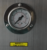
4.1.2 check if air pressure in the standard rating (04-0.6 MPa) range. Lower than 0.4mpa will affect the cleaning effect and reduce production efficiency (too low will not activate the machine).
Higher than 0.6mpa can result in damage to the mechanical gas system and all parts of the system.
Adjust the pressure method: pull upward gently to adjust the knob and rotate to the right————- Increase pressure
Go to the right ————– reduce stress
After reaching the required pressure, press the adjusting knob, air pressure lock and pressure to complete the gas connection, and the lamp is highlighted


4.1.3 check whether the top exhaust duct is unblocked or unblocked, which will result in damage to the environment and other consequences of the cleaning effect
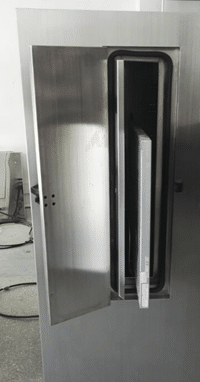
4.1.4 check the glass viewport of the door panel through the liquid road to check the solvent reserves. The normal state is above the M position, and the machine can meet the various cleaning effects. The amount of liquid stored in this model is the maximum amount (40L).

4.1.5 if the solvent is not enough, please add adding method in time: see adding solvent method
4.1.6 the pump access panel is opened with a randomly attached triangle key to check whether the ball valves are in normal condition
Ball (the ball valve of pump outlet filter) A ball valve D (pump inlet connection of the reservoir fluid Xiang ball valve) opens, B ((the ball) of white PE tube pump discharge ball valve C (white PE tube pump inlet ball valve) closed


4.2 time setting
4.2.1The setting of the cleaning time (see figure below), gently rotate the timer protection cap to the left and pull up the cover.
General cleaning time is
Minutes, depending on the actual situation, will be different.
This timer is measured in seconds (S) with a range of 10-999 seconds (S).
It can be set to 0, otherwise the machine will not start and may damage the timer and other components.

4.2.2 setting of drying time
Operation method and cleaning time setting.
The general drying time is 4-6 minutes depending on the actual situation.There will be an elongation of the aqueous solvents.
4.2.3The cleaning and drying time are automatic reset.
That is, one set, multiple times (N times).
When the pressure is less than the required number, the timer can be reset and the device cannot be started.
At this point, the black reset button on the upper row of the timer can be reset manually.

4.2.4The counter’s use of this counter is the increment counter, each cleaning a steel net, automatically into the system,
One of them is going up.
The count range is 0-999999.
Mainly used for cleaning work statistics, timely replacement of consumables (filter element), etc.
The filter cartridge should be changed when cleaning up to 1500.
Specific visual cleaning products are different and different.
When the counter displays the number to reach the target number, press the 4.2.3 method to open the cover, then press the black reset button on the left of the timer and the counter is reset.
4.3 placement of steel mesh
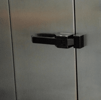
4.3.1 press the inner door safety button to open the cleaning room

4.3.2 lift the steel net with http://topmednorx.com both hands, gently place the front in the cleaning room chute roller and push it gently forward to the sliding channel steel
Fixed fixture on the net.
The steel net is in the middle of the fixture and chute. The top of the steel net is at the top of the cleaning room
Steel mesh fixture middle.(see below.)

4.3.3 when placing the steel mesh, the steel mesh shall not be in contact with the door to avoid damaging the steel net and sealant

4.3.4After the steel net is placed, close the cleaning door.
The inner door should be kept in good condition, otherwise, the solvent will be expelled outside, causing machine damage or environmental damage, more likely to cause personal injury

4.3.5 after the inside door is closed, continue to close the outer security door.
The security door is closed and the light is on, so that the following operation can be continued.
If the security door is not closed, the lamp will be retracted and the machine will not be able to start.
After closing the door again, the machine can be started

4.4 the start of the machine
4.4.1 press the start button lightly and the machine will start to run.
The machine will be automatically restored until the cleaning is completed

4.4.2 use the emergency stop button to press the emergency stop button when the emergency situation is in place. The machine will stop running.
The emergency situation is eliminated and the machine is restarted


4.5 adjustment of cleaning pressure
After the machine starts, pay attention to the pump input air source pressure and output cleaning pressure.
In order to achieve the best cleaning effect and maintain the tension of the steel mesh, the pressure should be adjusted

4.5.1 pump input air source pressure is generally maintained at about 0.4mpa
4.5.2 cleaning pressure is generally maintained at about 0.2-0.3MPa

4.5.3 adjustment of pump pressure: gently pull the adjusting knob of the pressure-reducing valve and turn the pressure on the right to increase the pressure to the left.
After adjusting well, press the adjusting knob to lock and adjust the work.
Note: this valve is the pressure reducing valve, the pressure adjustment will not be higher than the air source

4.6 the setting time is terminated and the machine is automatically stopped.
A cleaning cycle is over
5. Add, drain, and container for the solvent
5.1 addition of solvent
5.1.1 let the machine stop and open the access panel.
5.1.2 close ball valve B, D, open ball valve A, C.
Insert the “IN” pipe IN the ball valve C into the container containing the solvent.
Control the “IN” tube and start the machine until the machine drains the solvent.

5.2 discharge solvent and storage tank cleaning
5.2.1 open the liquid access panel and start the machine according to the normal procedure.
Close the ball valve D, open the ball valve C, and leave the machine idle for 1 minute.
In order to take out the solvent in the filter.
5.2.2 Open 8 screws on the tank and remove the reservoir cover..
5.2.3 press the stop switch to stop the machine.
Close the ball valve A and C, insert the “OUT” pipe of ball valve B into the container and slowly open the ball valve D.
Take care to control the “OUT” pipe at this time so as not to cause an accident.
5.2.4 when the solvent location of the reservoir is lower than the outlet filter of the reservoir, close the ball valve C and open the ball valve D.
Insert the white PE tube into the storage tank to remove the remaining solution
5.2.5When the solvent is removed, loosen the filter to fix the wire, remove the filter bag, remove the filter of the outlet and clean it with water or other means.
When the storage tank is cleaned and reloaded, cover the tank and lock the container
5.2.6 the liquid storage tank shall be cleaned and the solvent shall be drained and the machine shall be turned off.
Use a shovel knife to clean up the thick residues, leaving the small residue with a cloth strip
5.3 precautions for solvents
5.3.1 please wear protective equipment, such as protective gloves, protective glasses, protective masks, etc. to avoid direct contact with the human body and affect health and other safety accidents.
When operating, please pay special attention to the “IN” and “OUT” piping that controls the activity so as not to cause unnecessary security
6. Replacement of filter element
Replace the filter cartridge when cleaning a certain amount of steel net, the filter element needs to be replaced to satisfy the cleaning effect.
The replacement method is as follows
6.1. Remove the bottom of the filter with the left hand of the filter and remove the wrench into the disassembly hole, rotate the wrench to the left, remove the filter, then remove the filter element


6.2 installation of filter element
Wipe the filter clean and put in the new filter. (note that you can install a 5-micron filter on the outside by installing a 1-micron filter.
Then the left hand holds the bottom of the filter, and the right hand moves the filter nut.
When the hands are wrung, remove the wrench and hold it until it is unscrewed.
Pay attention to the filter cartridge when operating, the position of the filter should be put in place, for the positive
6.3 Replacement of seal rings
The sealing ring of the filter shall be soaked in the solvent for a long time because the chemical function will become larger. When the filter is removed, it will be difficult to install again.
The sealing ring should be removed at this time, with the spare ring installed.
Close the sealing ring after getting bigger, and substitute elastic back for backup
7. Use precautions
7.1. The installation site of the equipment is strictly prohibited near the source of fire, heat source and power supply.
The ground wire and exhaust duct must be installed and installed completely independently. It shall not be connected or connected with any other equipment
7.2. Replace the solvent, add, discharge the solvent, change the filter core, and when the steel net is taken, please wear protective equipment.To ensure the operator’s health and safety accidents.
7.3. Require strict access, adjustment and use of air source pressure according to the rated standard.Operate the machine according to the operating instructions and procedures of the machine.
7.4. It is not possible to bring cloth, paper scraps or other sundries into the machine cleaning room, or leave it in the storage tank, or it may cause blockage of the pipe and damage to the machine.
7.5. When operating the machine, please pay attention to the moderate intensity to avoid damage to the machine components.
7.6. No solvent cleaning machine surface or other non-stainless steel components shall be used to ensure the service life of the machine
8. Working principle

9.0 maintenance and fault handling
9.1 maintenance

9.2 fault handling