
Southern Machinery provides professional SMT peripheral equipment

HIGH SPEED DISPENSING OF SURFACE MOUNT ADHESIVE BETWEEN SOLDER PASTED PADS
HIGH SPEED DISPENSING OF SURFACE MOUNT ADHESIVE BETWEEN SOLDER PASTED PADS
Introduction
Surface mount
adhesive has been a part of electronics manufacturing applications from
the beginning of SMT. It has been used, in conjunction with wave
soldering processes, to successfully solder millions of components to
the bottom sides of printed circuit boards. In an effort to make the
manufacturing processes more robust and to improve the quality of the
assemblies, a solder paste printing step and a reflow soldering step
have been added to many traditional bottom side assembly lines. These
operations are added in order to decrease defects such as missing
components and insufficient solder joints. Both SMT (double sided
reflow) and Through hole (mixed SMT/THT) processes can benefit from this
process utilizing adhesive and solder paste. Some of the process
considerations are nozzle design, pad design, PCB layout, stencil
design, and adhesive properties. This article will deal with the
characteristics that must be considered in setting up this process, how
it can be implemented successfully, and typical line configurations
associated with this process. The major foundation of traditional
bottom side assembly processes is the adhesive.
Adhesive Selection
When selecting an
adhesive for applications involving the dispensing of surface mount
adhesives between solder pasted pads, it is important to choose an
adhesive that is formulated to give very specific rheological, or flow
properties. The adhesive selected should be formulated to allow for a
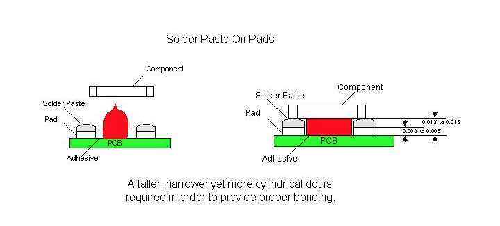
higher profile dot that exhibits very little slump. This will allow the
glue to contact the component, above the height of the solder paste
deposition, when the component is placed. Dots dispensed for this type
of application should have a tall, cylindrical shape as opposed to the
typical triangular Hershey kiss dot profile. The typical profile may
not allow the glue to properly adhere to the component prior to curing
and then hold the component through wave soldering. This will cause a
large number of missing component errors to be seen following the wave
soldering operation. Excessive missing components following manual
assembly may also be seen because the glue joint is not large enough to
provide the strength needed to hold the components in place.
The surface mount
adhesive chosen for these applications must also have a high green
strength in order to hold the component prior to the curing process. It
is this green strength that also helps the adhesive to maintain the
tall cylindrical dot shape needed when dispensing between solder pasted
pads. Without it the adhesive deposit will slump, losing contact area
with the component, and causing a decrease in the strength of the
adhesive joints.
In adhesive
dispensing processes utilizing heat, it is difficult to achieve the
necessary dot height. By applying heat to the adhesive, the material’s
viscosity is lowered, allowing it to flow more easily. This type of
flow characteristic will cause the adhesive dot to slump after
dispensing. Problems related to the adhesive not contacting the
component (missing components after wave soldering, etc.) will increase
in frequency, as well as the number of opportunities for defects such as
pad contamination to occur.
Board Design
Typically,
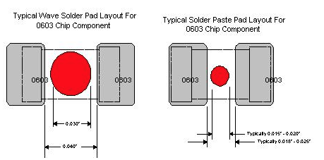
surface mount component pads are designed for either adhesive deposition
or the screening of solderpaste. The pad spacing is generally smaller
for solderpaste application as opposed to that of adhesive deposition.
For example, the component pad spacing between the pads of a 0603 chip
cap/resistor is typically 0.020”, if the board was designed to be screen
printed with solderpaste. The pad spacing for the same board can be
0.040” if adhesive deposition was to be utilized. A 0.030” diameter dot
of adhesive would easily be recommended for use if the component pads
on the board were indeed designed for adhesive deposition. However, if
the pad design for the same board was originally designed for
utilization of solderpaste, as a method of adhering the component to the
board, obviously, an 0.030” diameter dot of adhesive would be too
large, as the spacing between the pads is now 0.020”. A 0.015” to 0.018”
diameter dot is required for this particular application.
In designing pad
spacing and component spacing, the height of the pad and the solder
paste deposition must also be taken into consideration. Typically, the
height of an adhesive dot is one half the diameter of the dot.
Depending upon the material used for the pads, it would be possible
design a board which would be impossible to print and dispense adhesive
on. If the typical dot size for a 0603 component were 0.015” to 0.018”,
the height would be approximately 0.0075” to 0.009”. If the thickness
of the stencil utilized to print the solder paste was 0.006” to 0.007”
this might not allow the glue dot to contact the component body on some
types of board finishes. For example, a typical HASL finish is
approximately 0.003” thick. If the thickness of the stencil utilized
were 0.007”, the adhesive dot would have to be at least 0.011” to 0.012”
tall to properly contact the component. This would require
approximately a 0.022” diameter dot. This is why the rheology of the
adhesive is so important. If the adhesive slumps at all after
dispensing, it may not properly contact the component. The nozzle
design also plays a part in the development of the correct dot for each
application.
Nozzle Design
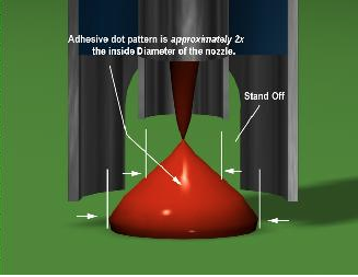
When selecting a nozzle for use in dispensing adhesives the main characteristics that must be considered are nozzle
design, standoff size and placement, and nozzle ID. A relationship
exists between these characteristics and the adhesive dot diameter.
When the adhesive volume is dispensed, the surface tension of the
adhesive on the board, should be twice that of the surface area of the
adhesive at the nozzle tip. If this condition exists, as the nozzle
retracts, the adhesive will snap off clean from the nozzle and leave a
well-defined dot of constant volume on the board. The nozzle must be
chosen based upon the size dot that is required by the application.
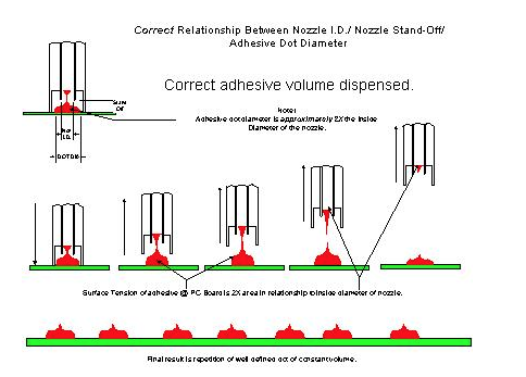
Nozzle selection
refers in this case to specific nozzle specifications for a known dot
size requirement. The dot size requirements can be derived from the
board design being utilized or specifically the pad spacing of
components. Reference pad spacing previously discussed in this paper. It
is not uncommon for Manufacturing Engineer personnel or Quality
Engineering personnel of a printed circuit board manufacturing facility,
to inquire what a recommended adhesive dot diameter should be for a
particular component type. Much has been written in regards to
recommended surface mount component pad designs and layouts for bottom
side applications. Topside pad designs are also used on bottom side PCB
fabrication. However these guidelines are rarely utilized. The pad
spacing for a particular component for each individual customer product
is unique.
Because the pad
spacing for most typical surface mount components is not standardized
from one customer product to another, it becomes a challenging task when
recommending what tooling should be utilized to satisfy a particular
customers’ adhesive deposition requirement for a particular component.
Note that the
volume of adhesive needed to maintain the component in place during the
high speed placement or wave solder process may be larger than possible
for some specific pad designs.
The nozzle standoff
can be defined as the distance from the tip of the dispensing surface
to the end of the mechanical standoff. The nozzle standoff is used to
maintain the distance between the PCB and the dispensing tip. Most
dispensers in use today are designed to utilize some sort of mechanical
standoff with the nozzles. The standoff usually dictates, to some
degree, the height of the dispensed dot
Typical designs for
nozzle standoffs are the castle design, the post design, or a dual post
design. For applications utilizing surface mount adhesive between pads
that have had solder paste applied to them, a single post design nozzle
is the most appropriate. In this type of application the standoff
should be set at 45 ° , 135 ° , 215 ° , or 315 ° around the pad circuitry.
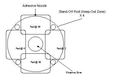
When selecting the
correct nozzle ID a rule of thumb is that the nozzle ID should be one
half of the required dot diameter. This will allow for the correct dot
diameter to be dispensed so that the glue snaps away from the nozzle
without contamination. By beginning with this guideline, the
approximate nozzle diameter can be determined, and then adjusted based
upon the material utilized.
Stencil Printing Considerations
When printing
solder paste prior to dispensing surface mount adhesive, there are some
stencil design considerations that must be taken into account. The
thickness of the stencil is important because it will determine the
height of the solder paste depositions. This also determines the
minimum height of the dot that must be dispensed in order to properly
contact and hold the component. In applications where wave soldering
will follow manual assembly, a smaller stencil thickness may be used
because the ultimate solder joint quality will be determined by the wave
soldering operation. It may also be beneficial, on pads with very
tight pads spacing, to undercut the stencil so that as much space as
possible is available for adhesive deposition.
Adhesive Curing
When printing
solder paste and dispensing epoxy between solder pasted pads a
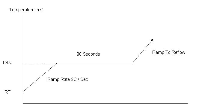
specialized cure cycle is required. Curing epoxy at 150º C is a
bondline temperature that should be verified with thermocouples at
various locations. Curing epoxy at temperatures above 160º C can cause
the adhesive to become brittle, leading to possible component loss
during the solder wave process. The solution for this is that the epoxy
must be cured at 150º C for about 90 seconds prior to ramping to the
reflow temp. This type of reflow takes into account the adhesive cure
as well as the solder paste reflow. Care should be taken to check the
quality of the solder joints achieved with this profile. The graph
below is a sample of what the cure cycle should look like. The final
profile should take into account the recommended profiles from both the
adhesive and from the solder paste manufacturers.
Placement Machine Considerations
When selecting a
placement machine for use in a process utilizing the dispensing of
surface mount adhesives between solder pasted pads, it is important to
consider the accuracy and the repeatability of the placement machine
down line. In typical top side applications utilizing solder paste
printing, when the solder paste is reflowed, the forces associated with
the solder, automatically center the component, within reason, on its
pads. When glue is added to the process this does not occur because the
glue resists these forces since it is cured prior to the reflowing of
the solder paste. It is important to consider all of the machines in
the line when developing this type of process.
Typical Manufacturing Line Configurations
Traditional Bottom Side Line

GDM Adhesive Dispenser
Vitronics Reflow Oven
HSP Chipshooter
Typically, a
traditional bottom side manufacturing line includes an adhesive
dispenser, a chipshooter to place the bottom side components, and an
oven to cure the adhesive. This line will be followed by a wave solder
machine, which will in turn be followed by an inspection and/or rework
station.
The first thing
that must be considered when setting up any manufacturing line is the
type of components and assemblies that are going to be used or built on
it. A traditional bottom side line can be used simply to apply glue to a
printed circuit board, place components on the board, and then cure the
glue in order to hold the parts onto the board prior and during wave
soldering and manual assembly. In this type of application the green
strength of the material determines whether components stay in place
during placement operation on the chipshooter. The post cure strength
of the adhesive determines whether or not the components will stay on
the board during manual assembly and handling. This makes the choice of
glue very important. After wave solder, using this type of line, parts
may be missing due to missing or unacceptable adhesive dots or some may
have be knocked off the board during manual assembly or handling. Care
should be taken to control the forces that these assemblies are
subjected to. This line is very basic in its functionality but can
reliably build products when implemented correctly.
Bottom Side Line With Solder Paste Application

HSP Chipshooter
DEK Stencil Printer
Vitronics Reflow Oven
GDM Adhesive Dispenser
A bottom side line,
that includes solder paste application, incorporates a system for
applying the solder paste (stencil printer or high speed dispenser), an
adhesive dispenser, a chipshooter for the bottom side components, and an
oven to cure the adhesive and reflow the solder paste. A wave solder
machine and an inspection and/or rework station will then follow this
line.
This type of
manufacturing line is more flexible than the previously discussed line.
For bottom side applications, this configuration provides greater torque
strength due to the adhesive being combined with solder paste. This
will assist in reducing the number of missing part defects present in
the assembly. This type of line also helps to reduce problems related
to the wave soldering operation (insufficient solder). In this type of
application, the dot height is important to consider because the dot
must be tall enough to contact the component even above the solder paste
deposit. Consideration also must be given to the design of the stencil
used to print the solder paste and the design of the nozzle used for
high speed dispensing operations. Both of these points can turn into
problems later if not considered properly.
Mixed Technology Top/Bottom Assembly with Solder Paste Application

Vitronics Reflow Oven
HSP Chipshooter
GDM Adhesive Dispenser
DEK Stencil Printer
GSM Flexible Placement
A mixed technology
line for assembling top and bottom side products includes a system for
applying the solder paste (stencil printer or high speed dispenser), an
adhesive dispenser, a chipshooter to place the bottom side components, a
flexible placement machine to place top and bottom side components, and
an oven to cure the adhesive and reflow the solder paste. A wave
solder machine and an inspection station will then follow this line.
The inspection station however, should see limited use because of the
robustness of this process.
This manufacturing
line is more flexible than either of the previously discussed lines.
Like the bottom side manufacturing line with solder paste, on bottom
side applications, this configuration provides greater torque strength
due to the adhesive being combined with solder paste. This assists in
reducing the number of missing parts present in the assembly. This
also helps to reduce problems related to the wave soldering operation
(insufficient solder). In this type of application, the dot height is
important to consider because the dot must be tall enough to contact the
component over and above the solder paste deposit. Consideration also
must be given to the design of the stencil used to print the solder
paste and the design of the nozzle used for high speed dispensing
operations. This line also can be used for topside applications
including the deposition of solder paste, chip placement and flexible
placement (QFPs and BGAs for example). This type of flexible
manufacturing line has become the choice for contract electronics
manufacturers because it offers a simple, total assembly solution.
Conclusion
The dispensing of
surface mount adhesives has been a part of electronics manufacturing
since the development of surface mount components. In an effort to make
the processes involved more robust, solder paste has been added to many
manufacturing line configurations. This configuration helps to
eliminate defects such as missing components and insufficient solder
joints following wave soldering.
In order to
implement this process there are a lot of considerations that must be
taken into account. The type of adhesive used must have rheological
properties that allow for a tall, cylindrical dot versus the typical
Hershey kiss shaped dot. This type of dot is required to properly
adhere to the component when it is placed on top of the solder paste
deposits. In order to obtain the correct dot height, the board design
must be considered carefully. By designing in the correct pad spacing,
implementation of this process is much simpler. The volume of solder
paste required must then be determined as well as the design of the
stencil. The required adhesive dot size must be considered when
designing the stencil. After the board is designed and the volume of
solder paste required has been determined, a nozzle must be designed to
provide the correct dot diameter with standoffs that will not become
contaminated with solder paste. After the adhesive is deposited and the
chips have been placed, the glue must be cured and the solder paste
must be reflowed. The profile used for this process must be developed
from the adhesive and the solder paste manufacturers’ recommended
profiles. Finally, the type of assemblies that are going to be built
must be considered when developing a manufacturing line that will meet
your needs now and in the future.
By carefully
considering all aspects of your manufacturing process, the dispensing of
surface mount adhesives between solder pasted pads can help eliminate
defects associated with typical electronics manufacturing processes.
This process helps to eliminate problems such as insufficient solder
joints. In applications where only glue was previously utilized, this
type of process can help eliminate defects such as missing components,
that can occur as a result of handling and manual assembly. By taking
time to consider the characteristics of your manufacturing process, the
correct line configuration and process parameters can be developed to
build the highest quality assemblies possible.
Southern Machinery WARRANTY POLICY ON ALL NEW Machines
WARRANTY POLICY ON ALL NEW Machines
Southern Machinery warrants its products to be free from defects in materials and workmanship for a period of one year from completion of installation, provided the products are installed as specified by Southern Machinery, maintained by qualified service personnel and the products are operated in accordance with published operating procedures. For purposes of the foregoing warranties the “completion of installation” shall be that date, within 90 days of shipment of Southern Machinery’s products from its factory, on which the products are installed and operating to the published specifications. If the customer believes a product to be defective in material or workmanship, or failing to meet the specifications, the customer shall notify Southern Machinery of such alleged defect or failure. Southern Machinery shall have a reasonable opportunity to investigate any alleged defect or failure, and upon confirmation of its existence Southern Machinery shall promptly remedy the same by repair or replacement, at its discretion and without charge. The seller warrants parts repaired or replaced for the duration of the original warranty period.
The warranty does not apply to:
1. Consumable parts as they are defined in this document.
or
2. Defects or failures as a result of non-compliance with U Southern Machinery’s installation specifications.
or
3. The customer’s failure to perform the recommended normal maintenance, set up and the adjustment of the equipment.
or
4. The customer’s alteration / modification to the equipment without Southern Machinery’s prior written approval.
or
5. Damages to the equipment resulting from non-compliance with published operating procedures.
or
6. The use of replacement parts not supplied by Southern Machinery or Southern Machinery’s approved suppliers.
Definition of Consumable Parts (Non Warranty):
A) Machine parts that come in direct contact with component processing.
Examples are, but are not limited to, insertion head tooling, chain clips, lead cutter tooling, etc.
B) Maintenance/bulk items.
Examples are, but are not limited to, lubricants, adhesives, light bulbs, fuses, seals, o-rings, etc.
All other machine parts are warranted for 12 months from the machine in-service date, completion of installation.
Disclaimer Statement:
The life expectancy of consumable tooling is dependent on proper preventive maintenance, proper machine set-up, and the type of component used by the customer. A customer may experience greater life expectancy or less life expectancy depending on the above.
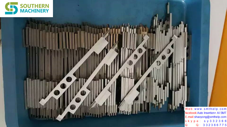
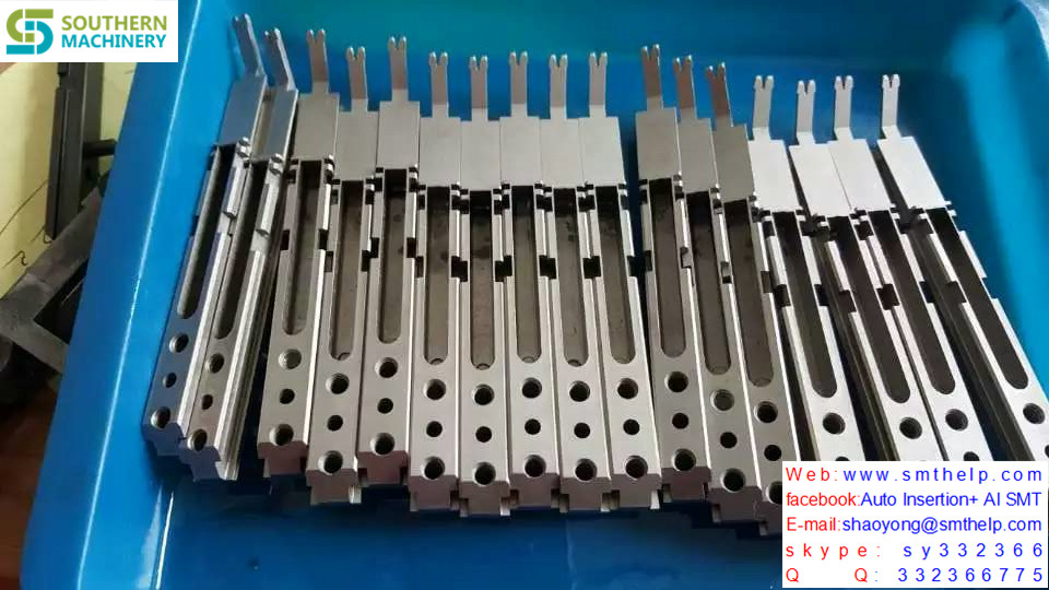
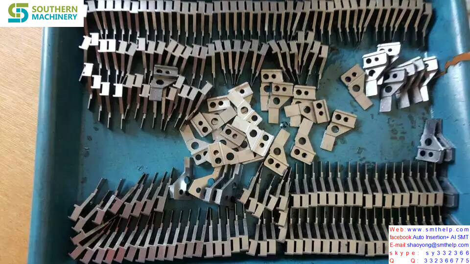
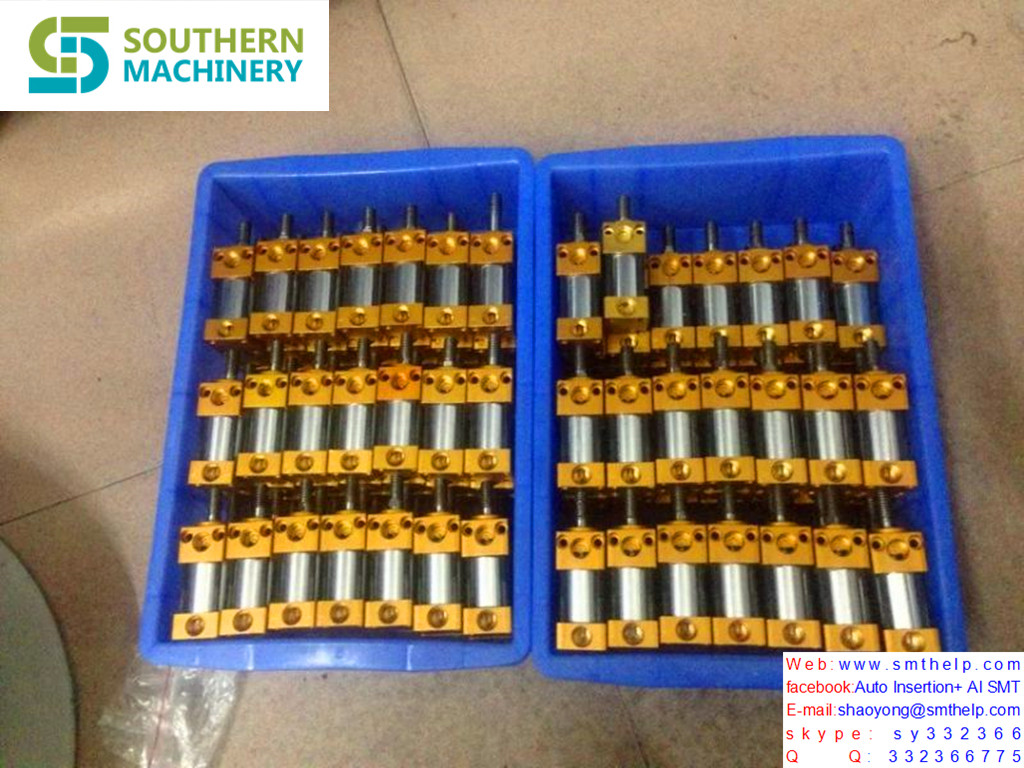
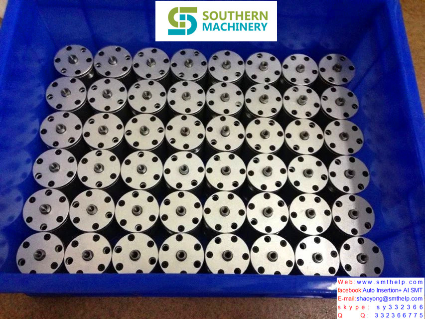
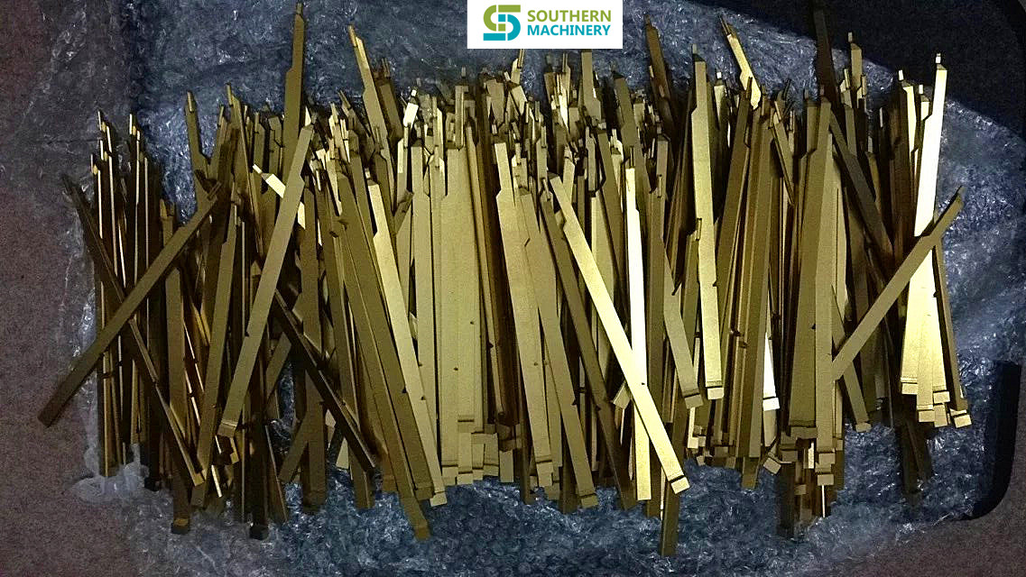
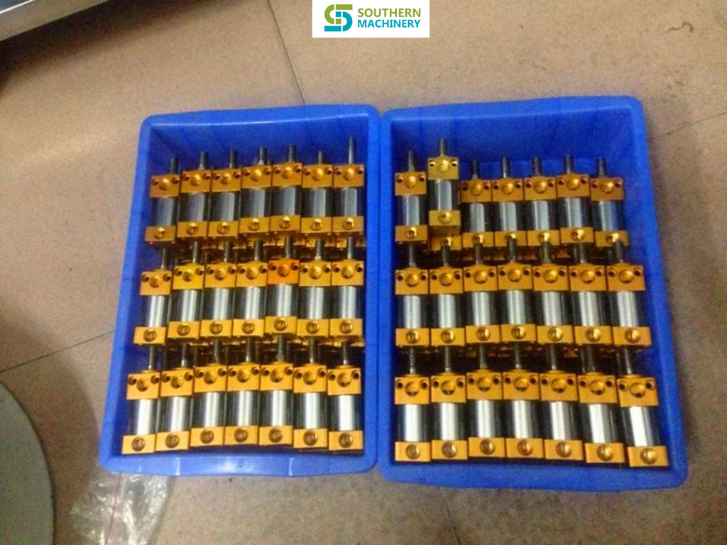
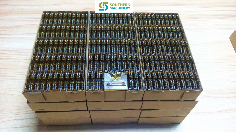
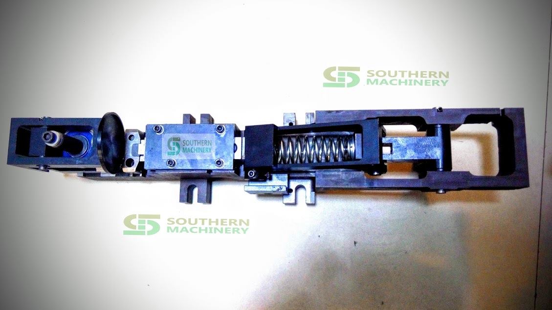
AI spare parts


How to analyze common failure case of reflow soldering
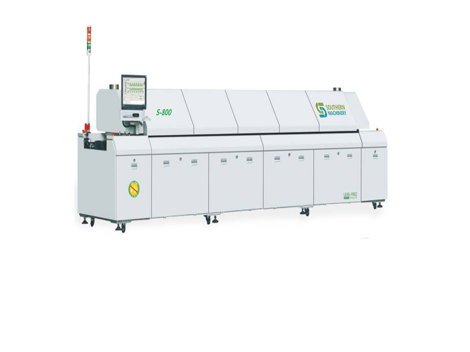
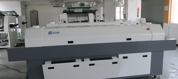
A common fault handling of reflow soldering is analysed
Reflow soldering heat alarm prompt temperature difference is too big or too small, in the process of computer tip ‘communication failure can’t start the machine, according to the two kind of phenomena, we had a lot of test and analysis work, draw the following conclusions:
1, in the process of reflow soldering heat suddenly alarm prompt “temperature range of a certain temperature too low or a certain temperature and set temperature difference is too large”.
Aiming at this phenomenon, we can preliminary judgment fault will occur in the heating or part overheating protection, and so will all overheat protection switch sub let its failure, and start the machine, found that seems to be normal.After further analysis, under the condition of the overheating protection switch sub machine can work, but in the event of heating, the temperature rise too high a less protection of defense, will bring more serious consequences.In order to solve this problem, we must put 16 from heating unit to find out one or several thermal protection switch failure, we will each heating unit with this problem apart, examine its overheating protection switch, found problems the second heating unit overheating protection switch, with a moving contact bimetallic strip fixed weak, cause the moving contact and the static contact point contact is not good, or not at all contact (normally two contacts should be contact together and conduction).Because there is no the second heating unit of the spare parts to replace we will switch sub to ensure production run smoothly.To this can solve the problem, but as soon as possible to the broken overheating protection switch is off, so as to achieve the purpose of protecting the second heating unit.
2, if the downtime is longer, when it turns switched on again reflow computer tip ‘communication failure and can’t start the machine for a long time to let the heat.
Aiming at this phenomenon, we preliminary suspect as the communication line fault, then replaced the telecommunication lines, the question remains, so denied this conjecture.After further observed, when the communication is not successful, the lights on the status of the controller is not normal, orange lights should be flashing, and should not go out.Based on manual measuring line 1001 and line voltage between 1007 found that the voltage is not constant for the + 5 VDC, about + 2 VDC when communication is not successful, the problem is out of here, why the voltage is too low, the original control panel in the end of the machine here are two simulated load resistance, resistance ought to be ‘5’R , but actual value only two ‘2’R, but I have measured the value to change it into ‘5’ R problem is resolved.
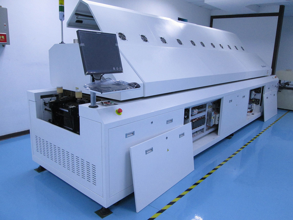

5 Reasons for you to choose LED SMT assemble line from Southern Machinery
24 hours online service for LED SMT assembly machines:

1)What is high speed SMT pick and place machine ?
The high speed automatic SMT mounting machine is the equipment used to realize high-speed, high accuracy completely automatic mounting the electric elements like LED light sphere, electric resistance , electric capacity etc. It is the mot essential and most complex equipment in the entire SMT production. The mounting machine is the major machine in SMT production line, and it is already developed from the early low speed mechanical mounting machine to high-speed optics mounting machine, and to multipurpose, flexible connection modulation development.
2)What machines does the LED board processing need ?
The LED mount technical process simplification is: Printing, Pick and placing, Reflow Oven (in each part, you can join examine link to control quality)
3) What are the advantages of Southern Machinery SMT pick and place machine ?
a.Top high speed in the world, quick than the main SMT machines brands like Siemens, Fuji, Samsung, Panasonic, Sanyo;
b.Lowest power consumption, 2.5-3.5KW/Hour;
c.Match vacuum pumps along with the main machine, no need to match extra vacuum pump;
d.Electric control system is installed on the top of the main machine, easy to maintain, and has a good damp proof effect;
e.Integrated forming steel frame, guarantee our mounting machine a stable performance on high speed running conditions.
f.The distance of sucking mouth can be adjusted manually, photoelectric will make sure the accuracy after adjust, allow you to mount different pitches PCB board.
4) What kinds electric elements can use our high speed SMT machine !
The main elements our machine can mount include: LED lights, electric capacity and electric resistance, sizes like: 0805,1206,2121,2835,3014,3528,5050,5630,5730,RGB; mainly for 1.2-1.5 meter LED light tube, LED panel light, 0.5-1.0 meter LED light strip , RGB strip.
5) What is our main business scope ?
We are the leading manufactuer of SMT LED mounting machines in Shenzhen, China, and we can produce and supply you all the SMT processing needed machines to you, mainly include: LED PCB board mounting machine, PCB board printer, PCB board reflow oven , and other related SMT devices.
For more detailed information about our LED SMT assemble line, email us freely, and you are warmly welcomed to visit our factory for SMT devices business !
What service you can enjoy if you purchase machine from us:
-
1. AI/SMT PCB Design Guidance
- How to improve machine’s efficiency,save more workers for you.
- Starting from the PCB layout and component specifications.
- Considering the potential of equipment,
- how to make the machine’s actual speed to be theoretical.PCB size ,
- how to custom can make more efficient
-
2. AI/SMT Technology Process Of Import
- First insert or pick&place?Step-by-step to guide you for designing your PCB production process.
- The new product programming, transfer line, how to deal with many varieties of small batch ?
- How to reduce the production process defective rate?
- Improve the continuous optimization
-
3. Equipment’s installation And Technology Training
- What position does your equipment should be installed in the workshop?
- Teach you how to layout the workshop for most conforms the technological process, save workers.
- Care about the more precise assembly and installing your equipment more than you.
- Equipment installation before/after have comprehensive training courses.
- We have English training courses and years of experience to install abroad.
- We not only training the AI/SMT machine, we study together, progress together.
- 4. Machine Trouble Shooting/Retrofit/Overhaul/Relocating
- Equipment production status 7X24 hours in the Cloud End, managers “anytime” “anywhere” insight into equipment production, state;
- Factory technical experts can 7 x24 hours online video consultation equipment technical fault, the cloud initiative to monitor and remind equipment maintenance;
- We upgrade your machine, you increase your productivity;
- And maintenance of the annual/full access to our professional engineer, they well, you must be able to get beyond your expectations of harvest;
- 5. AI/SMT Machine Accessories
- Equipment 7 x24 hours in the “cloud”, we offer equipment spare parts list according to equipment real-time state, and supported the use of PC equipment direct orders to buy;
- We have many years of AI/SMT machine accessories design, production and manufacturing experiences;
- We service life of spare parts, as well as spare parts affect the quality of the products for machinery and equipment and , and that, we willing to help our customers;
- We not only provide wearing parts replacement, more willing to provide you with technical guidance;
- We have professional engineers to electronic boards, motors and so on to provide maintenance services.
“Southern Machinery – World’s Choice for SMT/THT Machines & Spare Parts”
“Southern Machinery – World’s Choice for SMT/THT Machines & Spare Parts”
What is the high cost-performance of SMT spare parts
What is the high cost-performance of Smt spare parts from JianFeng Feng
Our compary provide professional solution of AI/SMT and SMT peripheral equipment,
if you want to learn more please contact us.
