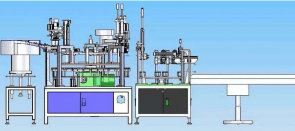
How to use Bowl vibration feeder for Bulk Electronic components for PCBA

For the last 20 years any odd-form components that did not come pre-packaged have been assembled BY HAND. Any PCB Assembly in today’s market can gain quick advantages by automating their assembly line. Huge costs are spent unnecessarily on labor and import fees.
If you are considering automation of odd-form components in your PCBA, consider these questions:
  1. Does your desired component come available in a package?
  2. Is your lead to hole ratio appropriate for automating?
  3. Is the quality and repeatability of the component suitable for automation?
  4. Does your component require lead preparation prior to insertion?
  5. Does your process require that the component is clinched?
Need help with these questions? Let us know and we will help design your Odd-Form Assembly tailored to your needs!


[Canvasio3DPro templateID=”15″ objectID=”18″]

How SMT solder paste is mixed. Is there any quick way?

How SMT solder paste is mixed. Is there any quick way?

The solder paste should be fully stirred before using
Purpose: To make the flux and tin powder evenly distributed, give full play to various characteristics;
Mixing method: manual mixing or machine mixing can be; mixing time: manual: about 4 minutes machine: 1 ~ 3 minutes
1) Manual Mixing: Remove the solder paste from the freezer and open the cover until it returns to room temperature (about three to four hours at 25 ° C). Stir the solder paste with a stirring knife. If the cover is broken, tin The cream will become tin pieces by absorbing moisture.
2) with automatic mixer:. If the solder paste is removed from the freezer, there is only a brief warm-up period and you will need to use an automatic mixer to use automatic mixing without affecting the solder paste characteristics. After a period of agitation, the solder paste will. Gradual warm-up If the mixing time is too long, it may cause the solder paste to be higher than the operating room temperature, causing the solder paste to be poured over the board in one piece, and flow (bleeding) during printing, so be careful. Due to different machines, room temperature and other conditions change, will result in different mixing time, so before proceeding, please prepare enough test.
Stirring effect of the judge: Scraping part of the solder paste with a scraper blade tilt, if the solder paste can slide down smoothly, that is, the right to meet the requirements of the appropriate mixing time due to the mixing method, the device and the ambient temperature and other factors vary, should Do more experiments in advance to determine.

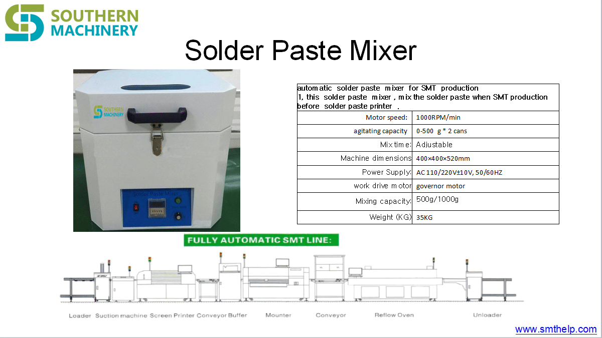
We have a fully automatic tin paste mixer which can solve these problems:

Solder Paste Mixer

automatic solder paste mixer for SMT production , this solder paste mixer , mix the solder paste when SMT production before solder paste printer .

Solder Paste Mixer-1

 the machine features Features:    

 1. 0 speed can reach 1000 rpm     

1.1 Solder Paste not need to first thaw stirring;     

1.2 do not have to open the container;    

 1.3 single-phase power supply 110v-220v:    

 1.4 No problem with water vapor:    

 1.5 does not destroy the shape of solder paste powder:  

  1.6 fixture for all kinds of 500g package Paste cans;    

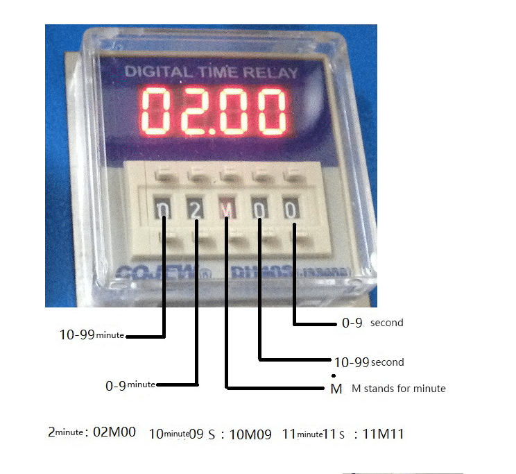
 1.7 mixing time can be set free;  

  1.8 with manual speed control


Solder Paste Mixer

Solder Paste Mixer

Solder Paste Mixer

DIP, PCB Assembly,Chip Mounter, Pick and Place, IC Mounter, High Speed Mounter, Wave soldering,LED lighting, LED Lamp, LED Display, LED tube,UPS, Power Converter, Power Adepter, Mobile Charger, PCB board handling system, Loader, Unloader, Conveyor,Shuttle, Chip Mounter, Pick and Place, IC Mounter, High Speed Mounter Induction Cooker, AC, Electric Cooker, Fan, TV, Settle Box

Reflow oven technology and precautions

Reflow oven technology and precautions

Far infrared reflow again

In 80s the use of far infrared reflow has the characteristics of fast heating, energy saving, stable operation, but because the printed circuit board and various components for different material, color and thermal radiation absorption rate to have very big difference, caused by a variety of different components and different parts of the circuit temperature is not uniform, the local temperature difference. For example, the black plastic package of integrated circuit will be overheated due to the high radiant absorption rate, and the welding part of it will lead to false welding on the silver lead instead of low temperature. In addition, the heat radiation blocked on printed boards, such as welding pins or small components in the shadow parts of big (high) components, will cause poor welding due to insufficient heating.

1.2 full hot air reflow again

Full hot air reflow oven  is a welding method by which the flow of airflow is forced through a convective nozzle or a heat-resistant fan, so that the welded parts are heated. This kind of equipment began to rise in 90s. Due to the adoption of this heating mode, the temperature of PCB and components is close to the temperature of the given heating area, which completely overcomes the temperature difference and shadowing effect of infrared reflow soldering, so it is widely applied now. In all hot air reflow oven  equipment, the convection velocity of the circulating gas is very important. In order to ensure that the circulating gas acts on any area of the printed board, the air flow must have a fast enough speed. To a certain extent, it is easy to cause the jitter of the printed board and the displacement of the components. In addition, in terms of heat exchange, the efficiency is poor and the power consumption is more.

1.3 infrared hot air reflow again

This kind of reflow oven is a more ideal heating method, which is based on the IR oven with hot air to make the temperature even more uniform insaide the oven. The characteristics of this kind of equipment to make full use of the infrared penetration, high thermal efficiency, energy saving, and effectively overcome the temperature difference of infrared reflow soldering and shadowing effect, and make up the influence of hot air reflow on gas flow caused by excessive demand, therefore  at international this kind of IR+Hot reflow is used most commonly  at present .

With the increase of assembly density and the appearance of fine spacing assembly technology, a reflow oven  furnace with nitrogen protection has appeared. Welding under nitrogen protection conditions can prevent oxidation, improve welding wetting power and speed up wetting speed. It is more suitable for uncleaning process to reduce the welding force and reduce welding beads.

2  The establishment of  temperature curve

The temperature curve is the curve of the temperature of a point on the SMA will change over time when SMA through the reflow oven. The temperature curve provides an intuitive method to analyze the temperature change of a component during the whole reflow process. This is very useful for obtaining the best weldability, avoiding damage to the components due to overheating, and ensuring the quality of the welding.

The following is a brief analysis of the preheating section.

2.1 preheating section

The purpose of this section is to put PCB at room temperature as soon as possible heating, to achieve second specific targets, but the heating rate should be controlled in the appropriate range, if excessive, will produce thermal shock, circuit boards and components may be damaged; if too slow, will not fully solvent, affecting the welding quality. Due to the rapid heating rate, the temperature difference in the rear section of the temperature zone is larger than that in the SMA. In order to prevent the damage of thermal shock to the component, the maximum speed is 4℃/s. However, the normal rise rate is set to 1-3℃/s. The typical heating rate is 2℃/s.

2.2 heat preservation section

The heat preservation section is the area where the temperature rises from 120℃-150℃ to the melting point of the solder paste. Its main purpose is to make the temperature of each element in the SMA stable and minimize the temperature difference.In this area, the temperature of the larger components can have enough time to catch up with the smaller components and ensure that the flux in the solder paste is fully volatile. The oxide of the soldering plate, the solder ball and the pin of the element is removed, and the temperature of the entire circuit board is balanced until the end of heat preservation section. It should be noted that all elements on the SMA should have the same temperature at the end of heat preservation section, otherwise, entering the reflux section will cause various bad welding phenomena due to the uneven temperature of each part.

2.3 reflow  section

In this area, the temperature of the heater is set to the highest, which makes the temperature of the component up to the peak temperature. In reflow sectionthe,the different of peak temperature is according to the solder paste to change, the general recommendation for solder melting point temperature plus 20-40℃. For 63Sn/37Pb solder paste with melting point of 183℃ and Sn62/Pb36/Ag2 solder paste with melting point of 179℃, the peak temperature is generally 210-230℃. Reflow time should not be too long to prevent adverse effects on SMA. The ideal temperature curve is the smallest area covered by the “tip zone” of the solder melting point.

DIP, PCB Assembly,Chip Mounter, Pick and Place, IC Mounter, High Speed Mounter, Wave soldering,LED lighting, LED Lamp, LED Display, LED tube,UPS, Power Converter, Power Adepter, Mobile Charger, PCB board handling system, Loader, Unloader, Conveyor,Shuttle, Chip Mounter, Pick and Place, IC Mounter, High Speed Mounter Induction Cooker, AC, Electric Cooker, Fan, TV, Settle Box

Reflow oven process principle and introduction

The reflow oven process principle and introduction

As we know,reflow oven is the most important welding technology in surface mount technology. It has been widely used in many industries including mobile phones, computers, automotive electronics, control circuits, communications, LED lighting and many other industries. More and more electronic devices are converted from through hole to surface mount, and reflow oven  replaces wave  soldering is a obvious  trend in welding industry.

So what is the role of reflow oven equipment in the increasingly mature lead-free SMT process? Let’s take a look at the whole SMT surface mount line:

The whole SMT surface mounting line consists of three parts, such as steel mesh solder paste printing machine, SMT machine and reflow oven furnace. For the machine, and compared with lead free, and no new demands on the equipment itself; for screen printing machine, and a lead-free solder paste in the physical properties there are some differences, so put forward some improvement on the device itself, but there is no qualitative change. the key of lead-free  is  in the reflow oven.

The lead paste (Sn63Pb37) melting point of 183 degrees, if you want to form a good weld must have the thickness of 0.5-3.5um intermetallic compounds in welding, intermetallic compound formation temperature is above the melting point of 10-15, the lead welding is 195-200. The maximum withstand temperature of the electronic device on the circuit board is generally 240 degrees. Therefore, for lead welding, the ideal welding process window is 195-240 degrees.

Because of the change of melting point of lead-free solder paste, lead-free welding has brought great changes for welding process. At present, the lead-free solder paste is Sn96Ag0.5Cu3.5 and the melting point is 217-221 degrees. Good lead-free solder must also be formed 0.5-3.5um thickness intermetallic compounds, intermetallic compound formation temperature is also above the melting point of 10-15 degrees, for lead-free welding, that is, 230-235 degrees. Since the highest temperature of lead-free solder electronic device will not change, therefore, for lead-free soldering, ideal welding process window is 230-245 degrees.
The substantial reduction of process window brings great challenge to ensure welding quality, and also brings higher requirements to stability and reliability of lead-free wave soldering equipment. Because the equipment itself is coupled with the electronic device transverse temperature difference, due to differences in size of heat capacity will produce temperature difference in the heating process, so in the process control of lead-free reflow oven can be adjusted in the process of welding temperature window becomes very small, this is the real lead-free reflow to the difficulty.


3D viewing SMT nozzle in THT PCB machine

[Canvasio3DPro templateID=”10″ objectID=”10″][/Canvasio3DPro]


We  Provide different spare parts and wearing parts of different brands and models.(UIC,TDK,Panasonic,Samsung,Fuji,Juki,SIMMENS……) Only need to tell us your partsmachine model and P/N. Fuji TDK Juki Samsung YAMAHA  UIC Panasonic

www.smthelp.com

Why Choice Us?

  • We owning 10 years experience in providing SMT/EMS services.
  • Familiar design and engineering capability both on Hardware and software.
  • Successful design experience in SMT line.
  • Lean manufacturing.
  • High mixed, high value, low volume business expertise service.
  • Flexible operation, fast response and total satisfaction.
  • Good after-sales and extra value creation services including logistics support, valet procurement, supplier audit service and in factory office offering.
DIP, PCB Assembly,Chip Mounter, Pick and Place, IC Mounter, High Speed Mounter, Wave soldering,LED lighting, LED Lamp, LED Display, LED tube,UPS, Power Converter, Power Adepter, Mobile Charger, PCB board handling system, Loader, Unloader, Conveyor,Shuttle, Chip Mounter, Pick and Place, IC Mounter, High Speed Mounter Induction Cooker, AC, Electric Cooker, Fan, TV, Settle Box

3D to show how SMT machine works

[Canvasio3DPro templateID=”7″ objectID=”5″][/Canvasio3DPro]

[Canvasio3DPro templateID=”6″ objectID=”4″][/Canvasio3DPro]

[Canvasio3DPro templateID=”5″ objectID=”3″][/Canvasio3DPro]

[Canvasio3DPro templateID=”8″ objectID=”1″][/Canvasio3DPro]