Please click below link to see 3D model:

Automated optical inspection machine (AOI) is a new type of testing technology. It has
developed very rapidly in recent years. The structure of AOI consists of four parts: workbench, CCD camera system, electromechanical control and system software. When testing, firstly, the circuit board to be tested is placed on the workbench of the AOI machine, and the detection
procedure of the product to be detected is called out through positioning. The X/Y workbench
will send the circuit board under the lens according to the command of the setting program. With the help of the special light source, the lens will capture the image required by the AOI system and analyze it, then the processor will move the lens toward the lens. The next position is
collected for the next image and then analyzed, and the image is subjected to continuous
analysis and processing to obtain a higher detection speed. The process of AOI image
processing essentially digitizes the extracted image, and then compares it with the pre-stored “standard”. After analysis and judgment, it finds the defect to make a position prompt, and at the same time generates image text, and the operator further confirms or sends the repair station. Overhaul
Please call me to chat:

Destacker Build Procedure SDM0029
Rev A
1. Obtain the proper shop packet and check order for build information. Pull all parts if any parts are missing, fill out a shortage sheet and give a copy to the appropriate material coordinator.
2. Pull the latest Electrical and Mechanical prints.
3. The following procedure is for a 29″ Destacker. Attach leg and control box to main beam. Leg should be flush to left side of main beam. Control box should be 3″ from right side of main beam. Attach width units to main beam, 4-3/8″ from either end square to main beam and Parallel to each other.
4. The following procedure is for the 44″ and 58″ Destackers Attach leg and control box to main beam. Leg 7-5/8″ from left end control box 7-5/8″ from right end. Attach width units to main beam 8.975″ from either end. Square to main beam and parallel to each other.
5. Attach rear rail to width supports parallel to main beam 3/8″ overhand from either end of main beam.
6. Level conveyor from side to side and front to back, off rear rail
7. Attach front rail to width supports. Match level to rear rail, especially front to back. Make parallel to rear rail. Make ends even with rear rail.
8. Install motors, pulleys, UHMW and belts on rails.
9. Attach Destacker assy to rails
10. Assemble valve pack assy and install
11. Attach air input assy
12. Attach front cover and wire into control box
13. Run pneumatic lines, load program software and test.
14. Complete check sheet, turn over to QC
End of Document


Preface

 When you shut off the machine power, please do it according to following sequence; if you do not follow the sequence and shut off the power or restart directly, the data can not be saved completely, it will also cause damage to hard disk. Exit/Shut off procedure: exit from application program exit from Windows turn off power
In order to avoid dust, you can cover up the machine(for example, put a cover), but must be moisture-proof.
Note: please pay attention to affairs mentioned above!
Chapter 1 Overview
S4000 series of machines can insert various kinds of tape packed components (electrolytic capacitor, porcelain capacitor, etc). The machine station can dispense material on special W-shape carrier clip, then carrier clips will be transferred to inserter and jump wire and various kinds of electronic component and jump wire will be inserted on PCB automatically, also showing the non performing status on display and detecting missing component, which shows the machine is a automatic equipment with high precision and performance.
One outstanding feature of this machine is: it is able to insert cylindrical jump wire to PCB directly without sequencing again, which can save 1/3 of jump wire. Supported by the self-developed software, the machine is featured with three functions all in one: it can not only insert jump wire alone, but also can insert axial electronic component alone, and can insert jump wire and axial component together as well. With one machine and one operator, it can achieve the output that equals to the yield of 40 workers inserting component manually.
1. Machine Technical Specifications:
| Item |
Technical Specifications |
| Insertion Rate | 24000 pcs/hr |
| Non Performing Rate | Less than 300PPM |
| Insert Theta | Parallel 0°,90°,180°, 270° |
| Component Span | Dual span 5.0mm-20mm |
| PCB size | Min:50mm*50mm; Max: 450mm*450mm |
| PCB thickness | 0.79-2.36mm |
| Component types | Axial tape packed material, such as capacitor, transistor, diode, resistor, blown fuse. |
| Clinch length | 1.2-2.2mm(adjustable) |
| Clinch degree | 0-35°(adjustable) |
| Station quantity | 60 stations(recommended),optional(10-100 stations) |
| Machine size (length×width×height) | Main unit 1700mm×1300mm×1600mm |
| Station size(length×width×height) | 510mm×1000mm×1410mm(10 stations) |
| Main unit weight | 1500KG |
| Auxiliary unit weight | 750KG(40 stations) |
| Power supply | 220V,AC(single phase), 50/60HZ, 2.0KVA; |
| System protection | Uninterruptible power supply (UPS) configuration, run 15 minutes after power outage |
| Working power | 1.6KW (Energy Saving) |
| Air pressure | 0.6–0.8MPA |
| Air consumption | 0.3m³/minute |
2. Machinery Part:
1) Mahcine stand
Based on scientific calculation, the machine stand structure is made of square iron tube welded with iron plate, then went through aging treatment, which ensures good rigidness and stability. The four corners of machine are installed with vibration-proof feet, whose height can be adjusted to achieve proper leveling of machine.
2) X, Y worktable assembly
This machine inserts component to each areas of PCB by moving the worktable, where the PCB is placed.
Each worktable assembly uses two hard steel shaft as rail, uses ball lead screw and servo motor in the middle to drive. Lead screw nut is fixed with platform board, and the two ends of lead screw is fixed, the motor is connected with it through timing belt. Motor drives lead screw to rotate, and lead screw drives lead screw nut and worktable to move in a straight line.
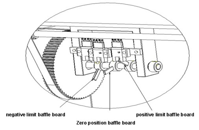
On X, Y worktable assemblies, there are positive and negative limits, reduction switch and zero position inspection optoelectronic switch. If the assembly moves out of first limit, the motor will slow down; if it exceeds second limit, the motor will slow down until stop to avoid destructive impact to servo system. The zero position inspection optoelectronic switch determines the position of worktable when it stops.
The X worktable assembly is installed on the main unit platform, Y worktable assembly is installed on X worktable assembly. The worktable board is made of imported aluminium of high quality, which helps to achieve light weight. Y worktable assembly is equipped with turning plate. The turning plate serves to allow the PCB to rotate in ±90°±180°±360° to insert electronic component in different directions. As to turning plate, there is a round rotating plate in Y worktable, the round rotating plate is supported and located by four bearing that are installed horizontally. At each side of round plate, there is V-shape locating bracket, normally, the “tongue” of locating structure of work plate stretches out and touches V-shape bracket closely to fix round plate. The locating structure is composed of two single-acting cylinders, one elastic “tongue” and locating board. When turning plate needs to rotate, air cylinder stretches out, “tongue” retracts and breaks away from bracket. The round plate rotation is driven by turning plate motor, the turning plate motor is connected with one elastic round wheel assembly through timing belt. The round wheel assembly is equipped with one air cylinder, when the round plate needs to rotate, this air cylinder stretches out, the edge of round wheel and round plate touches with each other tightly, the rotation of motor drives the rotation of round plate.
3) Inserter and housing assembly
The inserter is made up with encoder, motor, gear rack, bearing, and timing belt, etc. The inserter assembly is installed on square steel tube with size of 1001506. It is equipped with accessories of high precision and stability, such as motor, gear rack, bearing, synchronizing wheel, and a set of camera, etc.
The motion of inserter is realized by Panasonic servo motor controlling material transfer and insertion.
Note: the insertion motion steps as follows: material transferring is done by double chains of high precision carring component to inserter, then centering component by centering assembly which is of high accuracy, then the component is moved under the inserter by chain; at this time, insertion main shaft(H) gear shaft rotates after driven by servo motor, and brings gear rack to move downward as well as shear blade, then the component lead is cut off, the former moves down also and clinches the two leads of component, the whole component is bent into splayed shape; the pusher continue to move downward, and pushed the bent component into PCB. Meanwhile, driven by clinch motor, the two clinch air cylinder stretch out, and bends the two leads of component that is inserted already, and cut off the excess lead, then the component is fixed on PCB. After that, housing moves down and back to original position rapidly, insertion main shaft will move up and back to original position quickly. These motions will be repeated until next command is given.
4) Jump Wire Assembly
This machine can move jumper(jump wire) to the bottom of insertion head for insertion directly without being sequenced by sequencer. Feed motor rotates and drags jumper (jump wire) from left to right, while the jumper is straightened and moved to the bottom of insertion head to be inserted (same motion as electronic component insertion).
5) Electricity and Air Control Device
Electricity and air control device supplies power and control signal for machine.
All the motion command of this machine is input and output by computer. The detection signal is input to computer through I\O board, and motion command signal in input to I\O board or servo through computer.
This machine will use 220V AC, 24V and 5V DC, and it is equipped with UPS AC power source. There is leakage circuit breaker at AC power source trunk, and protective at each branch circuit. DC is supplied by switch power. Grounding system must be standard and reliable.
Every AC servo motor is controlled by one servo. All servo parameters can be read or adjusted through servo screen, or can be read and adjusted in computer with dedicated software. The servo scree can show error code of servo system, which means, the servo is able to “diagnose by itself”.
Air supply of machine is input by air control assembly and supplied to relevant aircylinder by each electromagnetic valve.
6) Camera Assembly
Camera assembly is used to on-line program and correct PCB insertion coordination automatically.
Camera assembly is composed of camera and light source. Camera is installed at the left side of insertion head, and locked on a holder that can be jogged up and down. The camera lens can adjust focus and distance; the light source is installed under camera lens and is used to aid shotting.
7) Servo Control
There are total 8 servo systems in this machine shown as below. The servo system ensures motion control with constant torque, wide-speed ration, high speed and high precision, which guarantees high performance of the machine. Since the motors use AC power, the machine is energy-saving.
Each servo motor is controlled by one servo. The signals of servo slow down, limit, and encoder are input to control computer; then servo is controlled by control card, station drive card and computer.
All servo parameters can be read or adjusted through servo screen, or can be read and adjusted in computer with dedicated software. The servo scree can show error code of servo system, which means, the servo is able to “diagnose by itself”.
Mature servo software and hardware technology ensures that error rate of servo system is almost zero.
| Item |
H shaft |
C1 shaft |
X shaft |
Y shaft |
C shaft |
C2 shaft |
B shaft |
W shaft |
|
Name |
head |
Sequencer chain |
X shaft |
Y shaft |
span |
centering |
housing |
jump wire |
|
power |
1000W |
750W |
400W |
400W |
400W |
400W |
400W |
100W |
8) Electric
This machine uses monophase power of 220V AC with frequency of 50HZ. Power consumption rate is 1600W.
This machine is equipped with UPS, which can keep the machine continue to work around15 munites and avoid waste of components waiting to be inserted when the plant has power outage.
Design of electric control circuit is very scientific,and material of electric component comes from famous brand with high quality.
Besides of 220V AC power, the machine also uses +24V DC and +5V DC through switch power.
9) Equipment / System Grounding
There is a grounding connecting wire on the machine for equipment/ system grounding. User is supposed to ground the machine properly to effectively control power obstruction and differential electric potential of large system.
Note: Please refer to international electric code and relevant local electric code to identify correct size and position of grounding connector. These grounding connectors are additional (not substitution) to the grounding wire for signal cable and power cable. The grounding connector of power cable also needs to be grounded, which is usually processed through conduit of wiring system. The ground must be powerless, not only neutral, you can not select power cable conduit as the only grounding point. If possible, the system power board should also be grounded. No matter what kind of grounding system is applied, the earth empedance must be maintained within DC-10mHZ and lower than 10OHmS. The grounding system should be separated from power obstruction source to prevent the obstruction from being transferred to equipement/ system through grounding system.
10) Adjust equipment leveling
After the machine is moved to target place, you can put down the machine foot and adjust the machine leveling by placing a leveling instrument on the machine. Proper machine leveling can minimize machine vibration and enable the machine to work more smoothly with less nosie and longer life.
Steps to adjust machine leveling:
Note: it will be rapid and efficient to adjust leveling by putting three feet on the ground.
11) File System Introduction
The D:\ disk in home directory contains following important file folders:
1) File folders S4000: the file used to keep application program S4000.exe.
2) File folders Installation: is to keep files that already registered for Southern Machinery AI equipment, it is temporary data file generated from registration.
3) File folders Southern Machinery data: is to keep parameters of equipment, component parameter, camera, original position test, statistic record, and factory default for relevant application program in Execl work sheet.
4) Equipment parameter: keep some parameters of AI equipment, such as insertion head excursion constant CX, insertion head excursion constant CY. Insertion head stroke constant HL, etc.
5) Component parameter: keep parameters of component specification, diameter, lead span for the equipment (the parameters can be added based on the type of component to be inserted).
Warning: Deletion or manual modification of above files is forbidden, otherwise the application program will be damaged and can not run normally, which will result in mal-function of equipment or even equipment destruction..
12) Industrial Control Computer and Software Installation:
1) Open mainframe box, install image collection card and motion control card
Matters need attention: be careful about ESD protection.
Installation and set up of motion control card: (1) make sure that your computer system is stable (2) make sure the computer is registered by Southern Machinery (3) make sure there are at least three PCI slots on computer mainframe (4) first run the file: D:\ install →Win2k_xp →PISO_DIO_Win2k_V241, then run REGIST2K in borad card, next run REG2K, then shut down the computer, insert the control card PISO-C64 into PCI1 slot, insert two DMC1000 (motion control card) into PCI2 slot and PCI3 slot seperately (5) open the computer, and copy Southern Machinery data and XG-2000E file folder into D disk, then install the safety dog into USB slot (6) after finish computer self-check and enter operating system, right click my computer attribute→hardware→ equipment device managers, click the “+” of Leisai Controjjer (motion control card), and find DMC1000, right click attribute driver→ update driver→ search for the suitable driver for my equipment → next step → appoint one place→ next step →browse (find D:\ install\board card\DMC100) and open→sure→ next step, the driver is installed automatically; the installation procedure of second motion control card is same, browse (find D:\ install\board card\REGISTER) open →sure→ next step, then the driver of the board card is installed automatically.
(7) Install P32-C32 motion control card, run PISO_DIO_Win2K_v241 in installWin2K and install. (8) Open and run S4000E.exe
2) Matters need attention: set up of computer mainframe BISO,
3) Divide computer into three areas: C: 20G; D: 30G; E: 30G; and formatting them all as NTFS system; NTFS formatting is more stable and reliable than FAT32. (Note: take 80G hard disk as an example, equipment does not have any special requirement for hard disk size)
4) Install system software WINDOWS 2000+SP3/SP4
5) Install computer mainframe driver
6) Install computer display card driver
7) Install motion control card
8) Install safety dog (4000) driver
9) InstallDatabase Driver
10) Install: WINRAR, five-stroke input methoh, Execl, etc. (not required by equipment, customer can install according to actual need)
11) Copy S4000E file folder
12) Copy Southern Machinery data file folder
13) File Backup
13) Computer Setup
1) Display color: 32 bits true color
2) Scree resolution: 1024×768 pixel
3) Set Screen Protection as “Non”, and Power Management as “Always on”.
4) Vertual memory: initial size: 500MB, maximum size: 1000MB
Attention: install and run antivirus software casually, because when AI is working, it needs to access to hard disk file frequently, and antivirus program usually first check read-write file, which affecting the AI performance and system stability. If the computer is suspicious of virus, you can create and install antivirus software, after destroying virus, uninstall the antivirus software or stop running it.
Warning: if data exchange with outside is needed, please make sure that outside device (USB flash disk, CD, Floppy disk) does not contain virus!
14) Safety Check before Operation
3. Machine Assembly Motion Chart:

Chapter 2 Installation
1. Tools come along with machine
1) One tool box;
2) A set of metric hex key spanner (9 pieces);
3) A set of open spanner (5.5-7 8-10 12-14 17-19 22-24 ) and a set of dedicated spanner;
4) A set of cross-shaped screwdriver and a set of slotted screwdriver;
5) sharp-nose pliers, diamond file, etc.
2. Install from “Part” to “Total”
Some parts of machine are broken down into pieces for the sake of packaging and transportation.
1) The sheetmetal door and front plate at both side of machine shell have been torn off, put the boards on the machine and lock the screw in relevant screw hole, and fit the boards to be aligned.
2) The warning light on machine shell has been torn off. First put wire through the installation screw hole of warning light, then turn metal tube into light installation screw hole and tighten the nut. At last, connect the wire one by one according to numbers.
3) Adjust equipment leveling
After the machine is moved to target place, you need to adjust machine leveling. Proper machine leveling can minimize machine vibration and enable the machine to work more smoothly with less nosie and longer life. The leveling of machine means adjust the stretch length of the adjustable plate on the four machine feet.
Steps to adjust machine leveling:
1) Place a leveling instrument on the machine workbench.
2) First adjust the machine right & left leveling; since the machine gravity center is in the rear part, thus adjust the two rear feet.
3) Then ajust the machine front and back leveling; you only need to adjust one front foot because three points finalize one surface.
4) Revolve down the foot hanging and revolve a little further, and tighten the locating nuts on four feet.
Note: it will be rapid and efficient to adjust leveling by putting three feet on the ground.
3. Connect Power and Air Resource
Attention please: before connect power, first make sure machine overall power and air supply are cut off.
Attention: please clean up the impurities in air pipe before supply air to machine.
Chapter 3 Operation
1. Safety Check before operation
Please you must pay attention: when machine is newly installed or in idle for long time, please do following safety check carefully before supply power and air to the machine and operate the machine.
1) Check if the power supply is appointed rated voltage
2) Check if power is connected to machine, if safety fuse is in good condition, and whether branch breaker is closed.
3) Check if the equipment is properly grounded.
4) Check if there are any irrelevant items left in power control panel and moveable part of machine.
5) Conveyor belt or timing belt derails during transportation.
6) Check the mechanisms that are of heavy load and running fast are connected well, such as lead screw, rail, insertion shaft.
7) Use hand to push and pull X, Y, H (insertion head), B(housing), C(span),C1(chain),C2 (centering), W( jump wire ) Assembly, whether they can move smoothly.
8) Check if each dispenser is retreat back at safe location.
9) Check if limit detection and limit assembly are dislocated.
10) Check if emergency switch is pressed down, check whether overall air supply and power supply are at OFF status.
11) Check if all connectors and air pipes of computer and power control panel are connected properly.
12)Check if UPS contains enough power, otherwire you need to charge it at least for 4 hours.
2. Power on and off
1. Power on
Before you turn on the machine, please make sure there is no impurity inside the machine, no jam in rear station, and no impurity on the chain; When power on, please do not put your hand or other stuff into the machine. This machine is controlled by industrial automation computer, it takes some time for it to start and be ready.
Operation order:
2. Power Off
In order to avoid damage to computer hard disk, and ensure completion of current production program and data, when shut off the power, please you must follow steps as below to shut down the machine properly.
Turning ON/OFF the machine repeatedly will be one of the causes of equipment and UPS errors. Once the power is off, please at least wait for 20 seconds before you turn on the machine again.
Operation order:


 Click Win2000 (Start) (shutdown), exit as normal procedure for Windows system shut down process.


Then switch off the general power of equipment, and turn UPS to Off status. If shutdown will last for more than 24 hours, please turn the equipment main power circuit breaker to OFF status.
3. Operation Interface Introduction, divided in 4 areas.

1. Control panel area: this area controls machine operation and production. (as picture above)
Explaination for buttons at control panel area:
Shift: It only shifts workbench, no feeding and insertion.
Idle spin: It moves workbench in order and idle insert, no feeding.
Insert: The sequencer chain and insertion chain run.
Single step: Except for “Start” button, in order to excute any function or open any file, you need to single click on it. During process of shift, and automatic insertion, if you click on it, shift will end and insertion will stop after every component. If you want to continue with automatic run, you must click on “automatic” again.
Automatic: Complete action in order based on program.
Single-cycle—continuous: It is a compound button. Normally, single-cycle means the machine stops after shift, idle spin or insert, and only after press start again, the machine starts to shift, idle spin or insert again. When you single click “Single-cycle”, the button becomes “Continuous”.
Feed jump wire: Click Jump Wire Assembly once, feed jump wire once.
Zero: Turn workbench, turn plate, H shaft, etc, to zero position. This is a must to zero all the mechanism before shift and insert for the first time.
Insertion head:It is head motor switch, green means effective, yellow means ineffective, at this time you can turn the head part manually.
Centering: C2 Assembly centers the material on the chain once.
Air Supply: Turn on or off all air supply of machine.
Rectify: Conduct visual rectify for coordinates in all programs, “Non” means no visual rectify, “√” means to do automatically rectify for the machine.
Start: Start the machine to conduct certain movement, and send out command of “Start”.
Stop: Stop all the motions.
Missing part inspection: Inspect missing part when inserting. Start missing part inspection function by putting “√” in the square grid; if no “√”, then no inspection for missing part.

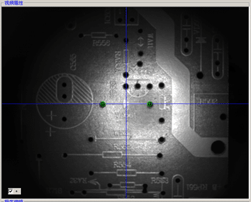
2. Vedio Attribute Area: This area shows the image of PCB taken by camera.
3.
Run-time information area: This
area shows production status and production information.
First, there is color indicating production status, green means normal, yellow means missing part, red means wrong part. Picture below shows the program names and program quantity of present production.
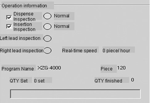
1) Program name: It shows the name of program that is going to run or has already run; it changes as you “run” different programs.
2) Quantity: It shows the total line quantities of the programs are running.(including 0S turn plate line)
3) Set quantity: Set the number of PCB to be inserted. When the quantity set is met, the machine will stop automatically. Normally, the quantity is set as 2 automatically. If you single click it, a dialogue box will pop out asking you “Do you want to set up target quantity?” If your answer is “Yes”, you can put the new target quantity directly. If the answer is “No”, click on “Cancel”, and return to previous interface.
4) Quantity completed: every time when inertion has done for one PCB, the production record will be updated automatically to show how many PCBs have been inserted.
5) Dispense inspection: it means inspect for missing part when transfeering components, if there is no component on corresponding chain, the machine will stop, and show yellow.
6) Insertion inspection: conduction inspection for missing part when inserting. Start missing part inspection function by putting “√” in the square grid; if no “√”, then no inspection for missing part.
7) Real time speed: actual speed of insertion.
4. Program edit area (such as picture): This area is to create or revise coordinate program where the program is open to manual edit. To enter program edit area, first click “single step” at control panel, then click the “edit” button at program edit area.

Edit: After click “single step” and “edit”, this button become yellow, and the chatacter becomes “exit edit” and the button box frame becomes dotted line, then you can edit the program. After you finish editing, click this button to exit. If you do not single click “Confirm” after editing, the dialogue box will pop up asking “The edit is not confirmed! Do you want to confirm?” if you select “Yes”, then the change will be saved, if “No”, the change is not saved. (Note:for founction column, only I1.I2.I3.I4 can enter into or exit from edit)
Visual correction: single step + edit, then click Visual correction, it turns to yellow, and image attribute area will show the image of PCB taken by camera.
Exit Visual correction: exit visual correction.
Excursion: when edit X and Y for the third row of program, this button will turn green, after you finish revising, and single click it before you exit from revision, then all the X, Y coordinates in all rows of the program will excurse automatically based on the revision done in third row. If you exit from revision after revising, and single click it, then the “excursion” is null. (Note: only under the condition of OS一the row is insertion row, there will be excursion.)
Enter: single click it, then all the revision done will be saved.
Up arrow: under the condition of “edit”, click it, will move to the program in last row. (Note: if the last row and next row is T1 or T2, then clicking on it is not allowed)
Down arrow: under the condition of “edit”, click it, will move to the program in next row.
Former: pusher tip goed down and bends component into U shape, but not insert.
Push: pusher tip moves down and push out component.
Reposition: pusher tip returns to original position.
Housing up: housing goes up..
Housing down: housing goes down and returns to original position.
Clinch clinch: clinch reaches out.
Clinch retract: clinch retracts to original position.
EXIT: After adjusting coordinate, if you want to repeal and you haven’t enter the adjustment, you can click it to return the coordinate to the previous value before adjustment.
Arrow button: when doing visual correcting, use arrow button to adjust coordinate. The direction of arrow indicated the movement direction of insertion head (namely the movement direction of workbench).
Number selection: the numbers 2, 10, 100, and 1000 means the movement distance of coordinate, you can select the movement distance by using “arrow button”. The ration is 100=1 mm.
C+: increase the width of C shaft.
C-: reduce the width of C shaft.
Rectify: choose “rectify current row” in control panel area, if you click it, the current row will be automatically rectified.
5. Explaination on Toolbar

1) File
single click: single step + file = open program, save program, save image, and exit(text format explaination: click on『single step』, then click on『file』 , then the fuction buttons like『open program, save program, save image, exit』will pop out, following same format are applicable to the same analogy)

Open program: open existing production program.
Save program: save production program to the appointed file folder.
Save image: save vedio image to the file folder at the same location as program.
Exit: exit from production menu, return to previous oprating system.
2) Quantity
Single click on quantity, function buttons like quantity set up, revise, end submenu will pop up. After ending submenu, you can revise the relevant quantity.
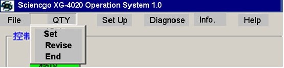
Set up:
set up the quantity needed for production.
Revise: revise the production quantity set as above. (Quantity needs to be smaller than the set up)
End:
end after the set up production quantity is achieved. (stop after all the componnets on the chain are inserted)
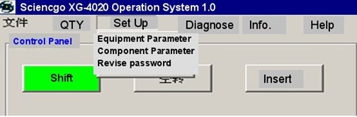
3) Set up
single click set up button, the dropdown menu,including equipment parameter, component parameter, and revise password. (shown as picture below)
(1) Equipment parameter (as picture):
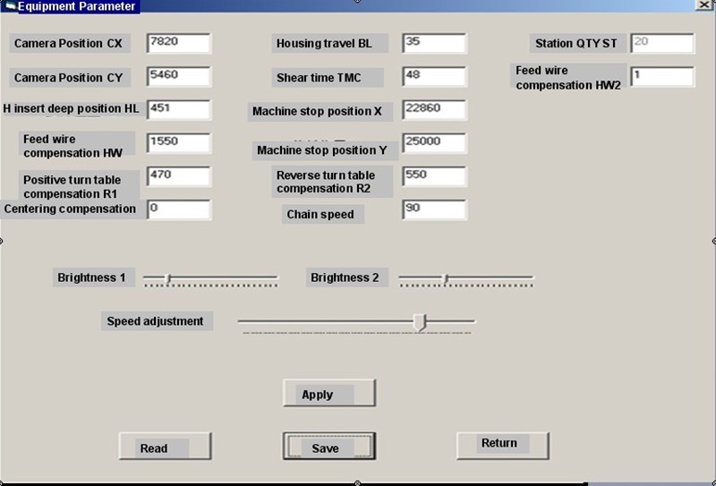
All machine parameters adjustment is done in equipment parameter, including camera position CX and CY, H deep insertion position HL value, feed compensation, turn table compensation R1 and R2, housing travel distance BL value, clinch time TMC value, machine stop position X(Y), camera brightness adjustment, etc. After you revise the parameter, you need to click application, save then click return.
Camera position CX: the coordinate for the center of a pair of former at X shaft based on camera center as zero position.
Camera position CY: the coordinate for the center of a pair of former at Y shaft based on camera center as zero position.
H deep insertion compensation HL: compensation for insertion depth of insertion head.
Feed compensation: compensation for jump wire length.
Centering compensation: compensation for travel distance of centering assembly.
Forward turn table compensation R1: when turn table rotates forward, compensation for the time to allow motor continues to rotate.
Reverse turn table compensation R2: when turn table rotates in reverse, compensation for the time to allow motor continues to rotate.
Clinch time TMC: working time of clinch motor.
Machine stop position X: after workbench zeros, the actual position of X shaft is bigger than zero position, usually is 22860.
Machine stop position Y: after workbench zeros, the actual position of Y shaft is bigger than zero position, usually is 22860.
Centering compensation: backup item.
Housing travel distance BL: compensation of rising height of housing.
Chain speed: adjust the speed of carrier chain and sequencer chain (C1).
Speed adjustment: adjust the overall insertion speed.
Station quantity ST: show total quantity of machine stations.
Feed compensation HW2: compensation for error value of feed wheel.
Camera brightness adjustment: adjust the brightness of picture taken by camera.
Application: apply default values that are saved.
Read: single click read, the default value will show up.
Save: save the parameters that get revised.
Return: exit from current page, return to previous operating system interface.
(2) Component parameter: component parameter is to classify all the components in insertion program according to certain criterion, and describe features of component. (If you want to add the component type, you can add it in component bank at D disk Southern Machinery data)
When you single click it, the following parameters will show up. (See picture):

Serial number: serial number of component.
Type: type of component, based on watt level.
Diameter: diameter of component body.
Lead diameter: diameter of component lead.
Component length: length of component body.
H speed: speed of insertion shaft H.
XYC speed: move speed of workbench and C shaft.
 + : single click it, the parameter of component with last “serial number” will show up. .
 : single click it, the parameter of component with next “serial number” will show up.
 Read: single click read, the default value will show up.
Save: save the parameters that get revised.
Return: exit from current page, return to previous operating system interface.
(3) Revise password:
Setting up equipment parameter password can prevent random change, if there is no password, revise can not be done. Before the machine leave the factory, the password for equipment parameter is set usually as 0000.
4) Diagnose
It is to diagnose the current status of input singal and output singal as well as the status of servo system movement.
Single step + diagnose= common input singal, common output singal, dedicated input singal, station driver, servo system, turn table, etc.
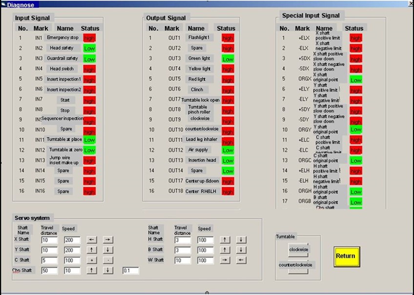
(1) Common input singal: it show current signal status of input channels, such as each photoelectronics, magnetic induction, safety switch, etc (input to computer through machine). The status described down is the machine standby status, when the machine works, the status changes between “high” and “low”, “high” and “low” are short terms of high level and low level. This control software is effective for low level.

Emergency stop switch: when press down the emergency stop switch on the shell, the status will change from high to low, all power of servo motor will be shut off.
Head safety: this in optoelectronic switch detection signal is used to prevent the H shaft from going down to unsafe position.
Guardrail safety: this switch is set up to proctect the moving door of machine. When you open the door, if you do not turn the safety switch manually, the low level will be released and all the working machines will stop.
Head switch: it is the enable control switch singal for servo of H shaft.
Insertion inspection: inspect the insertion status of two component leads. L and R represent the singal of left and right clinch. When inserting, if the component is not inserted into the hole or the clinch does not touch the component lead, the machine will stop or alrm. The normal status is high, otherwise it is low. The singal is from clinch, and the theory is that when the process is normal, the clinch and ground will form loop.
Start: when press down the start switch at machine shell, its status will change from high to low, the vise versa.
Stop: when press down the stop switch at machine shell, its status will change from high to low, the vise versa.
Sequencing inspection: when carrying the component while inserting, if there is no component on the chain, the machine will stop, its status will change from high to low, the vise versa.
Spare: the singal interface not used.
Turn table at place: when “at place” magnet on turn table approaches the “at place” magneto sensitive component of turn table sensor, turn table sensor will send out this singal. This determines the turn table whether stops or continues to rotate.
Turn table zero position: when “zero position” magnet on turn table approaches the “zero position” magneto sensitive component of turn table sensor, turn table sensor will send out this singal. This determines the turn table whether returns back to zero position.
(2) Special input singal: It is the signal status of current output (input to computer) by the optoelectronic switches on each shaft.

X, Y shaft: workbench shaft.
C shaft: the width shaft for cutting, forming and clinch.
H shaft: main insertion shaft.
C1 shaft and C2 shaft: insertion chain, sequencer chain shaft and centering.
Positive and negative limit: they are short terms for the optoelectronic switch singals of the maximum position at positive and negative direction of each shaft.
Positive and negative slow down: it is to send out signal of “start slow down”. They are installed in front of optoelectronic switch of positive and negative limit. When inspection sensor blocks the light emitter of optoelectronic switch, servo motor will start to slow down gradually and stop until it reaches the limit.
Original point: is to set up the detection signal of machine “zero point”.
——You can put a piece of paper between the light emitter and light receiver of each optoelectronic switch, normally the signal will change from low to high as the paper goes in and out. Otherwise the optoelectronic switches are broken or circuits are abnormal.
(3) Common output singal. It shows the status of each motion signal sent by computer. If you single click each buttom under “status”, movement status will change between “high” and “low”. “High”, means there is no movement; “low”, means there is movement.
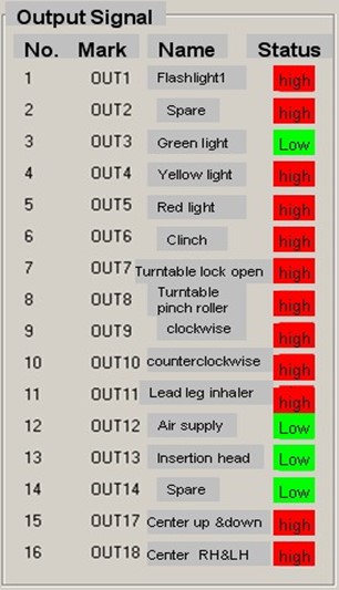
Flashlight: it is the light source of camera. This machine only needs one flashlight.
Spare: the singal interface not used.
Green, yellow, red light: the warning lights on the shell.
Clinch: control signal of electromagnetic valve for air cylinder of clinch.
Turn table lock: the electromagnetic valve for air cylinder on turn table lock assembly.
Turn table clamping roller: the electromagnetic valve for air cylinder on turn table lamping roller assembly.
Clockwise: relay singal that controls turn table rotate in clockwise.
Counterclockwise: relay singal that controls turn table rotate in counterclockwise.
Lead leg inhaler: signal of lead leg inhalation, not useful temporarily.
Air supply: singal for general air supply.
Insertion head: signal for head motor.
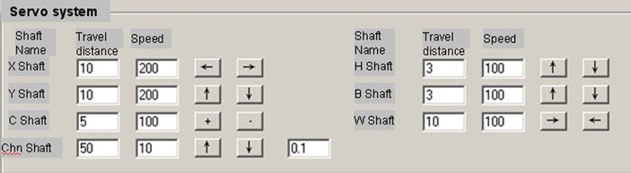
(4) Servo system (dedicated diagnose area for each servo shaft).
Input value within limit (blue number) in the input boxes of “travel distance” and “speed”of relevant shaft, when you single click the direction arrow (or direction button)once, the shaft will move once according to the value input and direction chosen, until the shaft reaches the limit and get protected (except for W shaft).
Among them, W shaft is shaft for feeding jump wire, and it only moves in one direction. B shaft is housing motor, C2 is centering,C1 shaft is insertion and sequencer chain, and other shafts have been introduced before.
(5) Turn table: It is the worktable that turns.

Clockwise: worktable rotates in clockwise.
Counterclockwise: worktable rotates in counterclockwise.
Return: exit from present operation interface and return to previous operation interface.
6) Station driver (shown as picture below):
 Press “-” button, station position will move one step forward.
You can put the target station in number input area directly.
Press “+” button, station position will move one step backward.
Press driver button, program start to execute the command input above, and test the station.

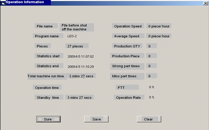
7) Statistics:
current production program information and operation information. If you select appropriate information, the selected information window will pop out and conduct statistics.

(1) Program information: show information of current production program. For example:

(2) Operation information: information including yield, standby time, insertion time, etc.You can save the information automatically into D disk “Southern Machinery data” file folder, “statistic record” file folder directory, the file is named by the time when it gets saved, when you click drop-down menu and exit from production menu, the information will also be saved here automatically.
Attention:
Save: press save button, then the information will be saved in D disk “statistic record”.
Zero clearing: press the zero clearing button, all operation information will be 0.
■Operation information: information including yield, standby time, insertion time, etc.You can save the information automatically into D disk “Southern Machinery data” file folder, “statistic record” file folder directory, the file is named by the time when it gets saved, when you click drop-down menu and exit from production menu, the information will also be saved here automatically.
6. Panel button explaination.


USB interface
1) Start: same function as the “start” on operation interface.
2) Stop: same function as the “stop” on operation interface.
3) Jump wire supplement: press the button, the jump wire missing will be supplemented at the same position.
4) Emergency stop: stop button under emergency, press the button, machine will shut off power of all servo motors.
5) USB: USB input\ output interface.
4. Operation procedure
1. Turn on machine power: switch on the main power circuit breaker at the left side of machine mainframe.
2. Turn on computer: “computer” button. The computer is installed right under the operation panel, after the machine cover is open, the computer will be seen.
3. Supply air to machine: click “air supply” buton on the operation control panel, the housing will get air supply.
4. Turn on emergency stop switch:
turn on the emergency stop switch on shell in clockwise.(the button will go up)
5. Conduct diagnose: check if singal status is normal, check if there is motion, check if machine control system is normal. Please see operation in Chapter 3, explaination of “diagnose” of each function “button” on operation interface.
6. Programing: Please see operation in Chapter 3, explaination of “program editting” of each function “button” on operation interface, as well as “program editing” in Chapter 4.
7. Access program: single click “file” on interface, single click “read program”, then single click the program name that you want to execute;set up “target quantity”.
8. Execute “visual correction” first then “idle spin”: “Visual correction”, please see
explaination of each function “button”, “program editing” on operation interface. The purpose of executing this operation is to check if the coordinates in the program are correct, and also check if X\Y workbench moves within safe range, ortherwise, the equipment will be damaged when conducting “Idle spin”. “Idle spin”, please see
explaination of each function “button”, “Idle spin” on operation interface. The purpose of executing this operation is to check if insertion shafts can move normally, and also “warm up” each working assembly.
9. Insertion, insertion chain and sequencer chain work.
1) First do: single step+ insertion, check the result of component insertion. If the insertion result is bad, please see Chapter 5, Adjust and Maintenance, “machine, computer parameter adjustment”.
2) After finish insertion of one board, check insertion result, see if component position is correct, is there any miss, otherwise add program……..
3) Conduct continue + insertion
10. Shut down the machine
1) Exit from operation system: Please see operation in Chapter 3, explaination of “exit from program” at operation interface for each function “button”.
2) Turn off computer: Please see operation in Chapter 3, explaination of “shut off computer” at operation interface for each function “button”.
3) Emergency stop: press down the emergency stop button on machine shell.◎
4) Switch off main power: switch off the main power circuit breaker at right side.
Warning: operating and maintaining this quipment by more than two persons is strictly prohibited, when maintaining the machine, please you must press down the emergency stop button on panel or shut off the power.
Chapter 4 Program Editting
Before inserting component to PCB, you must input a specific insertion program to computer. This program shows clearly: insertion sequency—-1,2 ,3…….;The position of first component on the machine workbench —X, Y coordinate value, namely OS position; the absolute coordinate(X, Y) value for the hole position of each component;and lead span value (C) of component, etc. This process of creating program, we call it as “program editting”.
1. Program Introduction
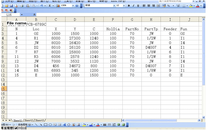
1) This equipment use Execl to edit program, and use metric absolute coordinate, then multiply by 100, and you can inreoduce the program of universal machine, DYNA machine, and masterplate, and edit it into the program applicable to this equipment. The picture below shows an example of program for a big board (wider than 20cm):
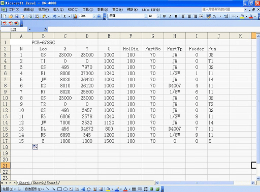

2)All the English letters for function code in above program sheet must be capital.
3) All the dimension value is actual metric mm multiply by 100.
4) Explaination of program content shown as below:
File name: first row and first column of program, you can name it at will.
Program name: first row and second column of program, you can name it at will, but need to make it clear that it is program for which kind of PCB.
N: second row and first column of program, serial number column. The sequency of machine executing programs (also the sequency of insertion).
L: second row and second column of program, position serial number of insertion point on PCB board, better to be completely same as the serial number on PCB board.
X: second row and third column of program, X coordinate column.
Y: second row and fourth column of program, Y coordinate column.
C: second row and fifth column of program, C coordinate column, namely the span of component holes.
H: second row and sixth column of program, diameter of PCB insertion point.
PartNo: second row and seventh column of program, serial number of component inserted.
PartTp: eighth column of program, the parameter colume tells machine that what is being inserted, component or jump wire component, it also controls the insertion depth of H shaft.
Feeder: second row and nineth column of program, station set up, feed material at which station.
Fun: insertion function column, code meaning shown as below ——
T1. command the workbench to rotate 90°in clockwise.
T2. command the workbench to rotate 90°in counterclockwise.
OS. Offset row of program, namely original point (OFFSERT) , this row is nominal row only, does not insert.
It is mandatory row; the next row right after it is the adjusting row for the coordinate.
I1. Insertion row, and conduct component missing inspection.
I2. Insertion row, but does not conduct component missing inspection.
I3. Norminal insertion row, it is error inspection row to detect off-standard insertion; this row executes insertion and inspection. When the PCB is not changed, or sequencer order error occurs or sequencer goes ahead, insertion will stop, this row is optional. It is set as the previous row of first insertion row with same coordinate as first insertion row.
I4. Jump wire insertion row, and execute inspection.
I5. Jump wire insertion row, and does not execute inspection.
E. Program end row.
2. Program editing procedure
1) Prepare tools: one digital caliper, two oil pens of different color, a sheet to create program.
2) First, based on BOM requirement, use oil pen to mark the component hole to be inserted and jump wire hole, use different color to mark the 0°and 90 °, because when insert component at 90°,turn table needs to rotate 90°.
3) Connect the marks with a line, based on the connect order, the insertion sequency will be defined. Connection principle: first, the line should be effective and shortest, that is to say, try to avoid idle travel of machine when inserting, it helps to enhance insertion speed and production efficiency;second, 0° and 90° need to be linked in two separate lines, because when insert component at 90°,turn table needs to rotate 90°.
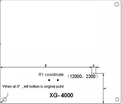
4) After drawing insertion sequency, use caliper to measure the coordinate data, the unit of data is mm. Before measuring the data, need to first confirm the two insertion locating holes on PCB board. Take clockwise continuous turn table insertion as an example, when machine zeros, the round plate rotates 90°and truns into 0°insertion status, after rotating the two locating holes on PCB board will be at left side of board, one up and one down, when we measure the coordinate data, we can use the left-bottom corner of PCB as O point (namely original point), the bottom edge of PCB can be considered as Y shaft of axis, the left side of PCB can be considered as X shaft of axis, thus, measure from left to right, the result is X coordinate data, measure from bottom to top, the result is Y coordinate data; when measuring X coordinate data, use the fixed tip of caliper to clip on left side of board, and use movable tip to clip on the right side of the insertion hole, the data shown on caliper is X coordinate data, need to keep two decimal places. When measuring Y coordinate data, use the fixed tip of caliper to clip on bottom of board, and use movable tip to clip on top of the insertion hole, the data shown on caliper is Y coordinate data, need to keep two decimal places as well. The distance between the centers of two holes on insertion component is span, namely C in Southern Machinery data. After measuring all coordinates at the 0° surface, then measure the coordinate at 90°surface. The picture below is the placement status of PCB board when measuring coordinate at the 0° surface:

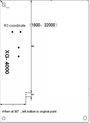
5) During normal production process, after inserting at the 0° surface, machine round plate will rotate 90° again, at this time , the two component locating holes are at the top of PCB, one left and one right. When we measure the coordinate data at 90°, we can still use the left-bottom corner of PCB as O point original point; when use caliper to measure from the left side of board to the right side, the result is X coordinate data; when use caliper to measure from the bottom of the board to the top, the data shown on caliper is Y coordinate data. The distance between the centers of two holes on insertion component is span. The picture below is the placement status of PCB board when measuring coordinate at the 0° and 90°:
6) After measuring coordinate data, create a EXECL worksheet in the file folder of D Disk “Southern Machinery data”, put down file name, and key in all the coordinate data into worksheet, and multiply the actual data with 100, and create the production program needed by Southern Machinery machine, when PCB is narrower than 20CM, the program shown as below: (following is the program of turn table rotates in clockwise, and insert continuously)

7) Following is the program of turn table does not rotate, only insert in one direction:
8) For the two program examples above, need to pay attention to following aspects:
(1) In the program of turn table insertion, the OS coordinates of every two turn tables must be aligned, and the sum of X, Y of T1 or T2 plus X, Y of OS on turn table is approximately 23000.
(2) Coordinate of I3 and I1 must be aligned, because I3 is to execute wrong component inspection, so its coordinate must be aligned with that of I1.
(3) The HolDia in program must be filled, and all English letters need to be in capital.
(4) The sum of insertion row OS and coordinate value of X, Y for I1.I2.I3.I4.I5 must not be smaller than 0 or bigger than 45000, if it is not in this range, then it is out of limit of X, Y.
(5) When inputting the items, no “space” is allowed in between, otherwise the machine can not recognize.
(6) In machine parameters, component type must be included; otherwise the machine component can not be inserted in place or not clinched.
(7) If the component span is in the range of 500-2000(5mm-20mm), then the program must be in in first worksheet of EXECL file.
(8) In editing area, if in last row turn table, it is not allowed to click up arrow ↑, otherwise workbench will hit shear pin.
7. Turn on computer, enter insertion machine operation system and keep machine at normal status.
8. (Shortcut) single click “file”——”open”, select the newly created insertion program file
Click—open or double click, then the system opens the program file, machine will execute this program.
9. Start “zeros”.
10. Start “shift”——”single step”, move to the first insertion row under OS, namely offset row.
Apply “program edit” and “Visual correction”, select the editing correction arrows up, down, left, right, and move unit distance 2, 10, 100, etc based on actual situation, and confirm the coordinate position of new offset row, when camera aligns with insertion hole, click offset confirmation button, and confirma new offset coordinate.
11 Apply “program edit” and “Visual correction”, according to above method, confirm the coordinates of each insertion rows under offset row, but you need to click “confirmation” button after revising the coordinate of each row. After corretting all coordinates, click file — save, save new coordinate program file.
12. When creating a new program in Southern Machinery format, input component position in column L (component serial number);input the diameter of insertion point in column D;input the component type in column P(parameter), JW is jump wire, **W is the watt of component;input the function code of machine motion T1 or T2 in column F(i.e. turn table rotates 90° in clockwise or counterclockwise);OS is OFFSET position, it determines the position of the first point on workbench; I1, I2,I;E is ending row, machine does not run this row.
13. After all machine insertion programs are corrected and saved, click panel shift — automatic— start, let the machine operates idle to see if the coordinate positions are correct. If all are correct, then you can start normal production next.
3. Verification program:
1)Set the PCB board in program stay at the original position.
2) After machine zeros, start single step + shift, shift to the second row of program (i.e.current row is insertion row), then click “edit” and “visual correction” in program edit area, see if the pount set and the cross picture of camera are concentric (standard insertion postion need to be concentric with cross picture),otherwise, use “edit” to correct.
3) Then click “exit from visual correction”, then click “Head” in the servo enable area of operation interface, turn off H shaft motor servo enable, hold H shaft adjust wheel and press down insertion head (need to have component clinched and to be inserted on the insertion head), see if the component lead can center the hole on PCB and be inserted properly, if can not center or can not insert, then you need to adjust the “equipment parameter” until the component can center and insert properly.
4) In “program edit” area, click down arrow, check if coordinates of each row are correct, if not right, thencorrect it.
5) At last (current row is
insertion row) , click “exit from edit”, then click “file”→”save program”.
4. Introduce other program:
1) Use “bitmap coordinate editor” to intruduce program.
The program created by “bitmap coordinate editor” is in text format; need to transfer the text file into EXECL. Open the text file with “EXECL”, and save, copy the content you need into the standard program format of this machine, and optimize other content.
2) Use”Board mold” data to introduce
You can transfer the format of PCB board data —-PROTEL99 into the program format can be used on the machine. This data is in text format also, and usually in British system, so you need to transder it into metric, and transfer the format from text to EXCEL. We only take the component lead hole WID X and WID Y data, copy the content you need into the standard program format of this machine, and optimize other content.
Attention: our company has the PROTEL99 software, you can ask for it. In order to keep the machine computer operate stablely, it is not allowed to install this software to the machine computer and use.
3)You can introduce the program used in other machine into this machine for usage.
Chapter 5 Adjustment and Maintenance
1. Machanical adjustment
1) Shear adjustment
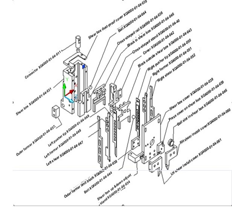
There are six shears in the shear box, left and right shear S4000-01-04-047, S4000-01-04-052, left and right outer former S4000-01-04-048, S4000-01-04-051 and pusher tip S4000-01-04-49, S4000-01-04-050, left and right bottom former S4000-01-04-046 , S4000-01-04-065. The installation standard of the shear: the clearance between top former and bottom former is 0.1mm,use your hand to feel the shear shking from left to right and no gap, and can move up and down smoothly; for bottom formers, the height of both sides must be the same, the S4000-01-04-069 and S4000-01-04-055 that fixing bottom formers can no have gap, otherwise it can not form properly. The picture below shows the break down pictures of each part of head assembly as well as relevant component serial number:
 2) Adjust of shear box S4000-01-04-031 and left and right shear stand S4000-01-04-026, S4000-01-04-027.
(1) there is a standard shear block for adjustment, the detailed adjust steps: first put the block into S4000-01-04-031, make it fits with blade guiding slots of S4000-01-04-026 and S4000-01-04-027, install S4000-01-04-060 and S4000-01-04-061 and lock the screw, then install the connecting pieces bottom U shaft lead screw left and right S4000-01-04-024., S4000-01-04-025, and the connecting pieces is to connect left and right spinning lead screws and S4000-01-04-026, S4000-01-04-027. The installation standard: after all connecting pieces are installed firmly, use hand to push the block up and down, you can feel the block can slide up and down in the shear box smoothly.


(2) After the core parts of S4000-01-04-026 and S4000-01-04-027 are installed, you can adjust the left bottom former and right bottom former. Adjust method shown as below:


After install and adjust above assembly, you can hang it onto head alumnium block.
3) Adjustment of component centering assembly
(1).component centering assembly is to conduct centering of component certer and insertion center in carrier clip before the component is inserted into the PCB board. Work theory—when air cylinder moves from fartherest dwell point to nearest dwell point, left and right certering arms will move backwards to component, while the left and right centering air cylinders decline gradually, V shape slot of left and right centering arms will move close towards center; with the clamp force of V shape slot of left and right centering arms, component is centered with insertion center by carrier clip through moving left and right horizontally; then air cylinder returns back to original position, left and right centering arms exit and return to original reposition. Break down picture of centering assembly as below:
Shown as above picture: 1. to adjust the centering clip to center left and right 3. it is up and down air cylinder 2. to adjust the downward depth of centering clip 10. it is left and right air cylinder, 6.to adjust the centering clip and component not aligned in Y direction.
4) Zero position adjustment
(1) Head optoelectronic switch adjustment
After original point optoelectric inspection block is settled down, open the diagnose in menu, use hand to rotate H shaft, and check the signal change of H shaft in dedicated input signal. There are three optoelectric inspection switches on H shaft, shown in picture below, they are: H shaft original point, H shaft positive limit, head safety, H shaft negative limit. The movement sequency is: when H shaft goes up, it will first meet head safety, H shaft original point, H shaft positive limit;rotate head in reverse direction, when insert down it meets with H shaft negative limit.

Adjustment method of H shaft optoelectronic switch as below:
a. To adjust the H shaft positive limit optoelectronic switch, rotate H shaft manually from bottom to the highest top, then move down by 1mm, move positive limit optoelectronic switch inspection piece from bottom to top, and tighten the screw of inspection piece immediately when it is triggered.
b. To adjust H shaft original point optoelectronic switch, rotate H shaft manually from bottom to the highest top, then move down by 2mm, move original point optoelectronic switch inspection piece from bottom to top, and tighten the screw of inspection piece immediately when it is triggered.
c. To adjust the H shaft negative limit optoelectronic switch, with the premise of normal distance between up former and PCB board, push the pusher tip farther than former by 1.5mm, adjust H shaft negative limit optoelectronic switchfrom buttom to top, and tighten the screw immediately when it is triggered.
If the sequency is recerse, H shaft will not return to original point position, it will move in reverse direction. Turn on H shaft power switch, and let H shaft retun to original position automatically, and see if the position adjustment can meet requirement, if not, then adjust again until the result is OK.
(2) Adjustment of C shaft

(3) Adjustment steps of C shaft and zero point limit switch:
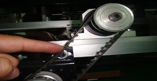
5) Adjustment of each motor timing belt
There are total six timing belt in the equipment transimission system, timing belt should be tight moderately. When the timing belt is too tight, they will be wron out easily, and affecting the equipment precision and efficiency. For example, if the clinch driver is too tight, the relevant bar will be bent slightly; if the transmission belt is too loose, then the issues of center span incorrect and clinch length change will occur together. The adjustment method of timing belt for each transmission part as below:
(1) Insertion head driver timing belt
The tensile force of this timing belt will change the set of H shaft limit switch, and will also affect the insertion tightness. If you want to check whether the tensile force is correct, you can put pressure on the driver belt span—0.45kg(1 pound), the pressure will pull down the driver belt radian by 10mm, if still need to adjust, please do as following steps:
(2) Housing synchronizing driver timing belt
If you want to check whether the tensile force is correct, you can put pressure on the driver belt span center—0.45kg (1 pound), the pressure will pull down the driver belt radian by 12mm.
(3) Adjust the X, Y driver timing belt
Put pressure on the center of X/Y driver belt span—0.45kg (1 pound), the pressure will pull down the timing belt radian by 6mm, if not achieved, please do as following steps to adjust:
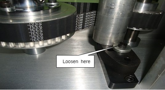
(4) Adjust the chain motor timing belt
Shown as picture below, loosen the screw and push the assembly up and down to adjust the tightness of belt to achieve proper tightness, then lock the screw.
6) Turn plate adjustment
Adjusting the rotating round plate should be done under normal operation environment temperature; it allows the round plate to rotate smoothly instead of having too much gap. Need to use gauge to support adjustment of rotating round plate. Only trained and professional personnel do following adjustment. Adjusting the driven bearing of round plate surface can allow it to rotate smoothly, there are four driven bearings on each turn plate, the driven bearing at right side is used to adjust centering, and the driven cam at left side is used to adjust over gap. After the turn plate in in place, the two driven wheels will control the turn plate when it rotates.
You should be careful when conduction following steps: do not move the four driven bearing plate at the bottom of turn plate, they are all calibrated precisely and can not be adjusted. (Note: before using gauge to adjust turn plate, the clamp must be work condition)

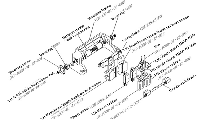
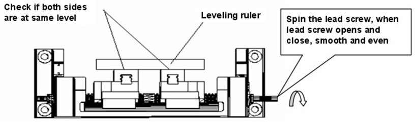
Fasten the left and right spin lead screw with long slider, connect the S4000-01-04-061 and S4000-01-04-062 on lead screw and slider, install two short sliders on the inner slot of S4000-01-04-061 and S4000-01-04-062; Adjust requirement: rotate the lead screw manually, lead screw opens and closes smoothly with proper strength, the two short sliders are sliding at the same horizontal level. You can use leveling rule to measure the alignment of the two sliders when they opens and closes.


(1) Adjust the clinch head
Install the O ring to piston bar S4000-01-12-020, and install them inside the clinch air cylinder S4000-01-12-014, seal back cover of the clinch air cylinder S4000-01-12-015, pull the piston bar S4000-01-12-020 manually, piston can move smoothly; when test air system, no air mix and no leak at each joint. You can also duck it in water to see if there is any bubbles to test the air tight, this method is visual and direct, and it is easier to judge there the installation is proper.

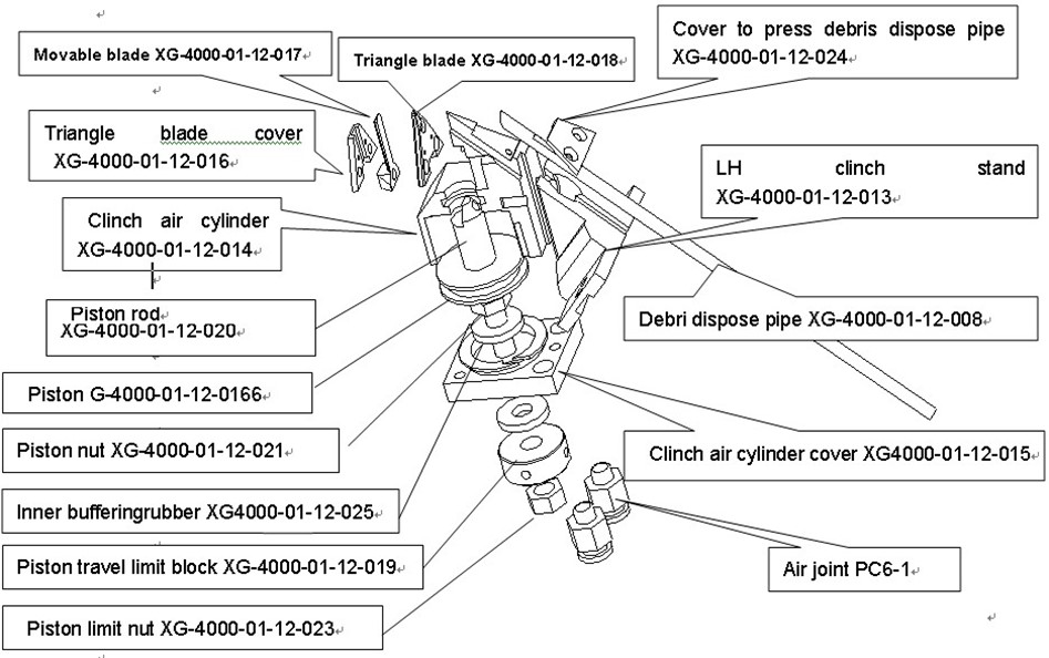


Overall housing structure as picture below:

Note: as picture above:
(3) Adjust housing clinch height
Housing clinch height is determined based on PCB board position, first put PCB on turn plate,since housing clinch is synchronized with housing motor, so we need to adjust the servo parameter of housing motor(when adjusting parameter, please make sure when housing motor is running, the highest point that clinch can reach can not higher than PCB board,otherwise you need to do machinery adjustment to lower down the clinch slightly) to adjust the height of housing clinch; when adjusting the parameter, you should adjust the parameter with small degree, then check the height of clinch. Normally the highest point that clinch can reach can not be higher than PCB, but the clinch can not be too low either, ortherwise it can not reach and clinch. The clinch should be lower than the bottom of PCB board slightly, you can press the center of PCB board, see if the PCB sinks down a little, then it is OK ( you can adjust the height according to actual productionrequirement)
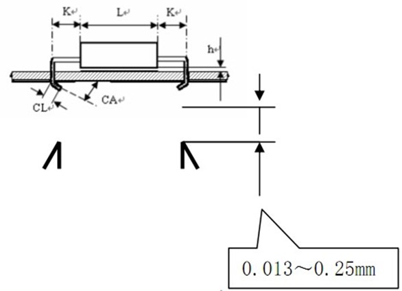
(4) Adjust the component lead angle:
When adjusting, you can put housing under the PCB at the proper position, but can not adjust the clinch length; when adjusting, you should turn on the air supply and the housing shoude be at up position. When the hosing is at up position, check if shear and clinch units are aligned horizontally and under the PCB by 0.013~0.25mm.
Adjust movable shear can increase or decrease the clinch angle of component lead. Adjust method as below:
Adjust outer former and PCB board


Set the clearance between outer former and PCB as 0.25mm (0.010in). When the thickness of PCB changes and causing change to depth locking, then you need to do following adjustment:
Move the insertion head up and down for several times, and check the gap again
 8) Adjust feeder chain
(1) Picture below shows the position of adjust chain
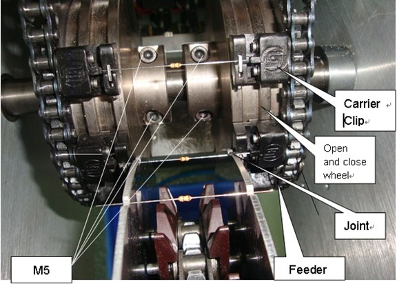
Steps as the picture shows:
1. First loosen the two M5 screw at the left open and close wheel, and tighten the two screws at right side.
2. As picture shows, place the component in the center approximately, left and right chains clamp the component leads tightly, and pull the left chain slowly, and set the two chain clips and component clamped at one line, then tighten the two screws at left side.
3. Enter machine operation system, diagnose interface, click Chr moving forward button slowly, the chain will move slowly. Use the special tool comes along with the machine to test the stablility of component (no leaning, no departure, no bend, no drop off, and material is under the shear by certain distance).
4. If the issue of leaning, bend and dropping occue, please adjust based on steps above until the component is stable.
9)Adjust material catching
1. Adjustment of material catching is the key of the whole machine, which affects the insertion quality directly. The parts need to be adjusted for material catching: material catching wheel, sequencer chain of W shape chain clamp, station. Work procedure: drive station to shear component → component falls on the W shape chain clip precisely and move with sequencer chain→sequencer chain moves component to material ctaching wheel → material catching wheel moves the component to the chain clip of feeder chain, the component is clamped and moved forward, material catching completed.
Shown as picture below: (1) driver station cuts component → component falls on the W shape chain clip precisely and moves forward with sequencer chain

(2) Sequencer chain moves component to material catching wheel

(3) material catching wheel moves the component to the chain clip of feeder chain, the component is clamped and moved forward:
1) Picture below shows adjustment of material catching wheel position:
1). Since the design dimension of two material catching wheel is same, and thereare two pin holes on each wheel at the same location, the two pin hole and the center forms a right angle, thus you can put special pin into the pin hole on the wheels to locate, which makes the V shape slot of the two material catching wheels at one line with proper balancing. Based on this theory, when adjust the material wheel, first loosen the locking screw of material catching where shown as picture below, then put the special pin into the holes at the edge; because the screws are loose, the material catching wheel can move left and right. Attention, the joint area of two material catching wheel and feeder chain clip, the distance between left material catching wheel and left feeder chain clip is 2 mm, the distance between right material catching wheel and right feeder chain clip is also 2 mm. After adjustment, tighten the screw of material catching wheel, and pull out the special pin, done.

2) Adjust material catching wheel and feeder chain clip
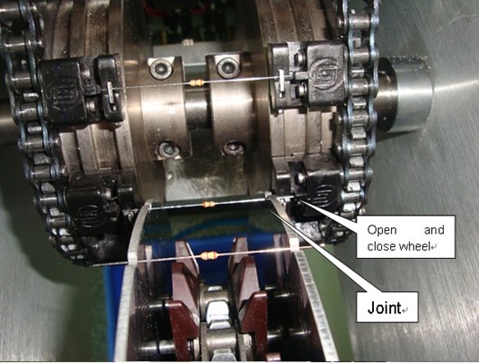
Theory: due to unique design of feeder chain clip and open and close wheel, when clamp piece of feeder chain clip moves to the joint area shown in the picture, under the force of open and close wheel, clamp pieces of feeder chain clip both hand are opened maximumly, and open position does not change. Since material catching wheel and open wheel are moving in synchronization, when material catching wheel moves to the joint area shown in the picture, component falls on the open feeder chain clip just right; due to unique design of feeder chain clip and open and close wheel, feeder chain continues to move forward, and the component is clamped and transderred. By this way, the next component falls on next feeder chain clip, thus the component is catched continuously. Because the open position is fixed, you only need to adjust the coordination between material catching wheel and feeder chain clip.
Adjust material catching wheel steps as below:
(1) Loosen the screws marked in the picture below at left side (total 3)
 (2) Remove the material shiedler marked in the picture below at the right side (it has 3 functions: adjust the component jump amplitude up and down; adjust the component move distance right and left; there are two brushes on the joint area, they can help component to fall on feeder chain clip up more precisely).
(3) After removing the material shielder, fix the special spanner on the shaft as picture above shows, put some components on the sequencer chain, roll the spanner in counterclockwise slowly, at the same time, see if the component can fall on material catching wheel precisely, after approximate adjustment, tighten the screw mentioned in first step, roll the spanner again, now see if if the component can fall on material catching wheel precisely. If component dislocates or drops off, please repeat the step 1.2.3 until it is stable,
(4) After it is stabilized, re-install the material shielder back, adjust the movement distance left and right, amplitude up and down, tightness of brush pressing component , after finishing these 3 steps, fix the spanner on the shaft and roll it at certain speed, see if each component can drop on feeder chain and get clamped tightly.
If component drops off, lead bends or not centering; please adjust the movement distance left and right, amplitude up and down, tightness of brush pressing component. (pay attention to tightness, if too tight, the component lead will get bent, if too loose, the component will not be pressed or drop off, so the tightness needs to be appropriate)到By now, the material catching is done.
(5) adjust the C shaft original point. After the material is caught, we can move the material on chain toward the upper former slot by 1mm further, now rotate the C shaft optoelectronic switch inspection plate to light up the optoelectronic switch and lock up.
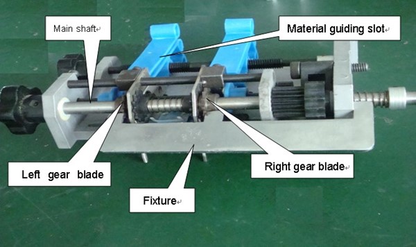
10) Adjust station. Replace the dull left and right main shears that not sharp enough.
(1)Loosen the set screw of main shear, take off the broken shear.
(2) Replace with new shear, and hang on the screw, but do not tighten it.
(3) Put the special fixture on the station as the picture. The tooth at the right side of fixture locates on the station surface, left side of the middle tooth fixes the outer surface of right gear shear, the right side of left tooth fixes the outer surface of left gear shear, and thus, the gear shear is fixed.
(4) Let the main shear blade surface stick to the outer surface of gear shear, and tighten the set screw of main shear.
(5)Remove fixture.
(6) Rotate the main shaft gentally, if not smooth, please install the fixture again, loosen the set screw of main shear to make the gap between main shear and gear shear bigger, then tighten the set screw.
(7) Load tape component, rotate main shaft, and check component lead the cutting, if the component lead bent after cut, please reduce the gap between main shear and gear shear again, or replace the main shear.
11) Adjust rear brake belt. Due to servo motor and other mechanic reasons, chain is not steady enough at the moment of start and stop, in order to minimize the unsteadiness; the brake belt is installed at the rear chain shaft. If not steady enough, when adjusting, need to tighten adjustment screw to tight up the brake belt; if the belt is too tight, the chain can not move smoothly, so the belt needs to be adjusted based on actual situation.

2. Adjust value
1) Adjust the parameter in computer
Refer to the introduction at Chapter 3 “each function button on operation interface”
2) Adjust servo parameter
Refer to servo introduction book comes along with machine
3) Adjust switching power this machine uses DC 24, 5 V power supplied by independent switching power.
1) The input voltage of switching power can select between 220V and 110 V, this machine uses 220 V, already set, do not adjust.
2) The output voltage can be adjusted around the nominal value, use multimeter to monitor the output, use slot type screw driver to rotate adjust button, when rotates in clockwise, the output voltage increases;when in counterclockwise, it decreases.
4) Adjust
camera
Attention: camera is precision component, it affects the coordinate and H shaft insertion position, break apart or adjust the camera at will is strongly prohibitted.
(1). Height height of camera determines the object distance and focus. First do rough adjustment, we set it as a rule: the distance between the camera bottom and PCB is around 148 mm. Then do fine tuning, need to use dedicated measuring scale, and adjust under Visual correction, select 1,5 or 10 mm as unit distance; click once, see if the cursor moves accordingly on the scale of measuring rule once; if not, need to adjust the camera position up and down; if still not right, then adjust the object distance and focus until it is right, then fix the position.
Please pay attention: after moving camera position, the H shaft parameter in “equipment parameter” may also need to be adjusted, because those parameters are set based on camera being “zero point”.
(2) Focus can be adjusted on camera lens. From top to buttom, the first is used to adjust object distance, rotate in clockwise and counterclockwise, the basic standard is the image is clear, then check if cursor move distance is same as measuring scale, then lock up.
(3) object distance can be adjusted on camera lens. From top to buttom, the second is used to adjust object distance, rotate in clockwise and counterclockwise, the basic standard is the image is clear, then check if cursor move distance is same as measuring scale, then lock up.
2. Equipment Maintenance
1) Daily maintenance
Daily maintenance should be done every 8 operation hours, if the environment is poor, then the machine should be maintained with higher frequency.
Warning: can not use compressed air to blow out debris, otherwise the debris will be blowed into all bearings, insertion head, shear/clinch or electric cabinet.
Note: if need to use lubricant to lubricate the machine, you can use 300B lubricant or equivalent.
(1) Add lubricant through the oil filling hole at the top of direction reversing shaft stand to lubricate the shaft sleeve shear/clinch unit.
(2) Use vacuum or brush to clean away the lead debris on shear/clinch unit or machine stable
(3) Clean up the waste in waste bin
(4) Clean up residual in waste pipe
2) Weekly maintenance
Weekly maintenance should be done every 40 operation hours, if the environment is poor, then you should shorten the cycle time.
Air driven lubricate device:
Warning: in lubricate device or air system, phosphate and chlorinated hydrocarbon compound can not be used.
(1) Check oil amount in lubricate device, if necessary, can add 100CKR lubricant.
(2) Shear/clinch unit.
a. Use cloth without soft flocks to wipe ball lead screw.
b. Lubricate ball lead screw slightly.
(3) Insertion head driver device
a. Use cloth without soft flocks to wipe ball lead screw.
b. Lubricate ball lead screw slightly.
(4) Feeder wheel driver device
—— lubricate both ends of connection bar
—— lubricate feeder wheel driver cluch.
—— Check if U shaft limit switch inspection board is loose.
(5) Workbench
—— Wipe and lubricate ball bearing part.
—— Check if limit switch inspection board is tight.
(1) Check the consistency of insertion head and zero point limit switch.
3) Monthly maintenance
Monthly maintenance should be done every 200 operation hours, if the environment is poor, then you should shorten the cycle time.
(1) Air driven lubricate device (air control assembly). Through sightglass, check the flow rate of air driven lubricant. Flow rate should be 3~5 drops every 5 minutes. Method to adjust flow rate: rotate the groove screw at the top of lubricate device towards the back of hopper cover, rotate counterclockwise/ clockwise can increase/reduce the lubricant flow rate, at beginning should set it open within 1/4~1/2.
(2) Shear/clinch unit
——clean rotating lead screw.
——add 20MR oil to the guide rail bottom.
(3) Insertion head
——add 20MR oil to the inner part.
Note: when breaking apart and assmble insertion head, need to add lubricate oil
(4) Check the leveling of PCB fixed plate
(5) Turn plate rotate device
——add 20MR oil to sliding device driver shaft, cam sliding device, stop trigger and set sliding device.
(6) Workbench
——use oil pot to apply 300SL36 oil on liner guide rail.
——add 300SL36 oil to the path of turn platedriven bearing wheel.
4. Regular Check
1) Round plate consistency
2) Check insertion head.
a. Check up and down bearing stands consistency.
b. Check for inner trap.
c. Check former travel distance back and forth
d. Check if the distance between inner and outer formers is same
e. Set correct C dimension.
f. Shear and clinch consistency.
g. Relieve timing belt tensile force.
h. Housing consistency.
i. Centering of up and down insertion heads.
j. Clinch angle.
5. Air driven part maintenance
A set of air driven device, if not get maintained properly, it will be damaged too early or break down frequently, and shorten working life greatly. When maintaining air driven device, if accident signal is seen, you need to take countermeasure timly to minimize or prevent breakdown from occurring, and prolong the working life of component and system. Thus, company should create maintenance managemen regulation for air driven device, strengthen management and education, and manage it strictly.
The key task of maintenance is to ensure supply clean and dry compressed air to air driven system, ensure air driven system seal tightness, ensure oil spray lubricate component to be lubricated properly, ensure air driven component and system to operate in regulated work conditions (like using pressure, voltage,etc) ,to make sure air driven execute assembly work according to requirement.
1) Air cylinder maintenance
The structure and theory of air cylinder is shown as picture1.

picture1
1. rear cylinder cover 2. Seal ring 3.buffering seal ring 4. Piston seal ring 5. Piston
6. buffering plunger piston 7. Piston bar 8.Cylinder barrel 9. Buffering throttle 10.guiding sleeve
11.front cylinder cover 12 dust-proof seal ring 13. Magnet 14.guiding ring
After break down air cylinder, first clean each component, then lubricate or seal one by one.
Piston maintenance air cylinder piston is pushed by air pressure and slides in side the barrels, which requires high flexibility of piston as well as good seal between piston and cylinder. The seal is achieved by YX shape seal ring, thus the YX shap seal ring is quick-wear part, please see its structure in picture 2.
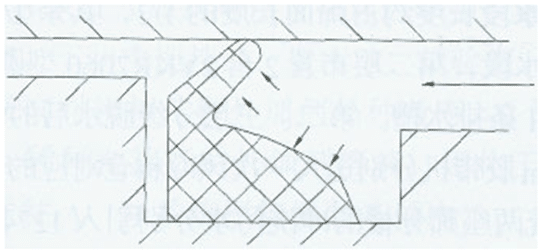
Picture 2: YX shape seal ring
There are two lips of same length at the fracture surface of YX shape seal ring, the seal ring is installed in the slot of piston, when its right side is pushed by air pressure, the seal ring lip will open due to the pressure, and stick to cylinder barrel tightly to achieve good seal. Please observe closely after the air cylinder is broken apart, if the YX shape seal ring lip has been worn out, the you should remove it and replace with a new lip; apply lubricate oil. Besides, the buffering plunger piston touches with cylinder cover frequently, so it also needs to be applied with lubricate oil.
Cylinder cover maintenance
When the air cylinder is working, piston will hit cylinder cover, so the cylinder cover buffering seal ring is quick-wear part; if the buffering seal ring is worn out badly, the buffering effectiveness will be affected due to poor seal between buffering plunger piston and buffering seal ring before the air cylinder stops. After using air cylinder for long time, it usually required to replace seal ring, and apply lubricate oil.
Cylinder cover buffering tends to be ignored easily, please be careful, screw down the buffering throttle, use thin iron wire to clean the buffering hole carefully (be careful do not damage throttle thread),otherwise, buffering venting hole will be blocked, which may cause piston bar can not be at proper place.
Cylinder barrel maintenance
Apply lubricate oil onn the inside wall of cylinder barrel, and install piston bar, at the same time pull and push it several times to ensure good lubrication and seal quality between cylinder barrel and piston.
After maintenance, you can assemble it.
―- When maintaining the air cylinder, you should pay attention to following issues:
After air cylinder is broken apart, you should first clean the cylinder barrel, piston, piston bar and cylinder cover, and remove the rust on surface.
(1) The lubricate oil can not contain solid additive.
(2) Select seal material according to the specific work, better choose polytetrafluoroethylene (teflon), the friction factor of this material is low( about 0.04), corrosion resisting, so the material can work within the temperature range of -800℃~+2000℃.
(3) When installing YX shape seal ring, be careful about the installing direction.
2) Electromagnetic valve maintenance
(1) The best method to make electromagnetic valve work reliably with long life is to do regular examination and repair one or two times per year. The following four kinds of situations inside electromagnetic valve are reason for electromagnetic valve abnormal and short work life.
A. medium changes during usage process
B. rust inside jointer
C. air compressor oil oxidizes, producing carbon granule, oil tar and so on, get into pipes
D. impurities like dust and dirt inside pipes
(2) Breaking apart electromagnetic valve coil block is not recommended.
(3) When break apart electromagnetic valve for cleaning, you can use some liquid like kerosene and triclene and so on, but please be careful the runner part may swell, so you need to replace the rubber part.
(4) When breaking apart the equipment for cleaning, please place the components in order, which helps you to install later.
3) Air supply filters use cleaning cloth to wipe and clean every three months.
4) Air lubricator better fill the air lubricator once every week, when filling, please pay attention to the oil reduce status. If the oil consumption amount is too little, you shoule adjust the drops of oils; if after adjusting, the drops of oils is still too little, then you should check if the oil mouth is installed resersely, and oil tunnel is blocked or not, whether the air lubricator specification is proper.
6.Dust cleaning
1) Computer mainframe check the cooling fan of mainframe once every month, use cleaning cloth or brush to remove dust.
2) Servo, motor check servo shell and its cooling fan once every month, use cleaning cloth or brush to remove dust.
3) Machine inside use cleaning cloth or brush to clean once every week, or use cleaning agent to wipe, and pay attention to moistureproof.
4) Machine shell use cleaning cloth to clean once every week. Using organic solvent to wipe is strictly prohibited to avoid damage to the paint on equipment shell. Please you must never use plate washer water, IPA to clean the printed letter.
Chapter 6 Basic Error Analysis and Solutions
1. Basic error analysis and solutions
Skills: first need to identify which part causes the breakdown, electricity, air system, machinar, or computer. Then check whether electricity, air, or power source are introduced or not, are they nominal values. Next check the connection or demountable section connected or not, or locked stably (wire connector, synchronizing wheel……). Check whether safety switch, protective switch, limit switch are under protective locking (scram switch, protective tube, limit optoelectronic switch, electric leakage switch, air-brake switch).
| Failure Area |
Symptom |
Root Cause |
Failure Resolution |
| Computer |
computer and display can not open |
panel computer power switch broken orconnection wire broken |
Replace or connect again |
|
Can not turn on computer, but display normal |
|
|
|
|
Mainframe can work normally but no display |
Check internal memory stick for loose connection or CPU for poor connection |
use eraser to rub the gold bar on internal memory stick, or replace CPU |
|
|
Shut off automatically after turn on the computer less than10 minutes |
CPU cooling fan loose, broken, or power voltage unstable |
Replace CPU cooling fan or check power circuit |
|
|
execl file format incompatible, can not open operation system |
Infected with virus ,Office has been damages |
Use lastest updated anti-virus software to kill the virus, delete all the execl files, re-install Office |
|
| XY servo system |
motor does not move |
Let servo exit from power connection, pull off the wire between servo and motor, push XY Assembly slightly, see if it can move or not | |
|
limit inspection board touches limit optoelectric switch |
Retreat the machine to original reposition, exit from limit position |
||
|
servo has no monophase 200 V output |
Check servo enable singal, I/O, replace servo |
||
|
Connector between servo and motor does not actuate |
Make emergency stop reposition, replace connector |
||
|
motor moves but abnormal |
motor broken |
replace |
|
|
Computer error (example:drift phenomenon) |
|||
|
synchronizing wheel not tighten |
Tighten it |
||
|
Improper parameter setting |
set up again |
||
|
timing belt aging |
replace |
||
|
servo or motor error |
check and repair or replace |
| Failure Area |
Symptom |
Root Cause |
Failure Resolution |
| Image |
5V power error |
Check 5V switch power, relay, wire connector |
|
|
light source not bright enough |
5V voltage too low |
Adjust standard |
|
|
LED broken |
replace |
||
|
Vedio no image |
Singal wire error |
Re-connect or replace |
|
|
Image vague, not clear |
camera not adjusted well |
Adjust aperture |
|
|
light source not bright enough |
Check 5 V or LED |
||
|
camera parameter setting in the system incorrect |
Tone up again andadjust exposure time |
||
|
Board too dirty |
clean |
||
| Machine back to zero position |
When machinezeros,click zeros, machine does not move |
Press down emergency stop switch |
Turn on the emergency stop switch in clockwise,turn on 24V power |
|
Turn off the organic glass door protective switch, make stop switch red light extinguish |
|||
|
turn table small board broken |
replaceturn table small board |
||
|
zero position switch is triggered, machine does not stop,continue to run |
zero position optoelectronic switch broken |
replace optoelectronic switch |
|
| feed |
feed length not same |
feed device is not adjusted well, or component broken |
Check and confirm the error and adjust again |
|
shaft joint loose |
Check if shaft joint set screw and anchor ear are loose or tightened, if trips, replace the worn out part |
||
|
Block when feeding |
Feeder stretched part is not adjusted well |
Adjust again |
|
|
feed pipe is blocked |
Clean the pipe |
||
|
S4000-01-04-054 broken, causing hook knife no elasticity |
replace spring S4000-01-04-054 |
||
|
servo parameter setting improper |
set up again |
||
|
S4000-01-04-065 broken |
replace left bottom shear S4000-01-04-065 |
||
| Coordinate displacement |
After adjustment, good for some time, then displace |
timing belt too loose |
adjust timing belt tightness |
|
X.Y shaft screw under the turn plate loose |
Check and tighten the loose screw |
||
|
anchor ear not tight |
replace anchor ear |
||
|
encoder singal wire broken |
replace |
||
|
motor or driver broken |
replace |
| Failure Area |
Symptom |
Root Cause |
Failure Resolution |
| Component falls down |
Component falls down |
S4000-01-04-058 , S4000-01-04-059 shakes heavily |
Replace S4000-01-04-055 or S4000-01-04-056, S4000-01-04-057 |
| Inner and outer formers broken |
Replace |
||
|
clinch air cylinder poor seal |
Check and repair |
||
| Shear |
Shear but not bend |
Housing cylinder breakdown |
Replace |
| Not shear |
Electronic valve that driving housing cylinder breakdown |
Check and replace |
|
|
Hollow pin brake or loose |
Check and replace |
||
|
S4000-01-12-017 or S4000-01-12-018 worn out |
Replace blade |
||
| Lead |
Lead is bent , but not sheared |
program coordinate problem |
Calibrate program coordinate |
| Insertion | wrong insertion |
S4000-01-04-040 pin loose |
Replace S4000-01-04-040 |
|
Forming issue |
Check gap between up former and low former and wearing degree,replace |
||
|
S4000-01-04-011worn out , big gap |
Replace S4000-01-04-011 |
||
| Turn plate |
Turn plate lock not release , turn plate not move |
Electronic valve that driving turn plate breakdown |
Replace |
|
Turn wire breaks |
Use multimeter to check and replace |
||
|
The two small cyliders that releasing turn plate are loose ,causing lock device can not open enough to drive turn plate |
Check and adjust again |
||
|
Turn table motor breakdown |
Replace |
1)Computer basic error analysis and solutions
Skills: first need to identify which part causes the breakdown, electricity, air system, Assembly or computer. Then check whether electricity, air, or power source are introduced or not, are they nominal values. Next check the connection or demountable section connected or not, or locked stably (wire connector, synchronizing wheel……). Check whether safety switch, protective switch, limit switch are under protective locking (scram switch, protective tube, limit optoelectronic switch, electric leakage switch, air-brake switch).
(1) Installation of driver
Normally for a hard disk that just get system installed or recovered ,still there are several drivers not installed, such as mainboard, display card, sound card, USB controller, etc.
a. Installation method:
First check the driver that not installed yet, go to device manager, see picture as below, if there is mark of “!” or yellow “?” in the yellow circle for the option, then it means the driver of the option is not installed. Right click the option, and install the driver by selectting “Update Driver” or using the disk that come with computer (shown as following picture).

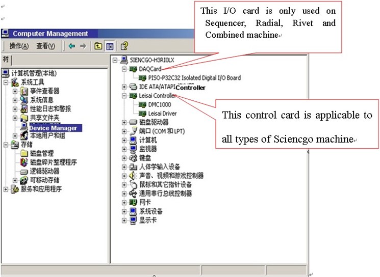
This screen shows the driver is installed for control card (PISO-P32C32 and DMC1000)
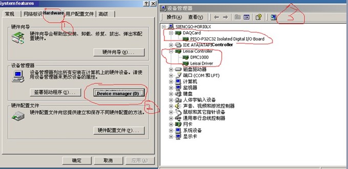
b. File backup
In order to avoid loss of production data, we recommend every two or three days, use clean USB falsh disk that without virus to copy the Southern Machinery data folder and camera folder as backup.
If the machine shows “execl table incompatible” or “file format incorrect “, please conduct overall virus detection and destruction under safe mode, and install Office software again, then delete all files that have execl table.
c. Set up of Display
1.Display color: 32 bits true color
2.Scree resolution: 1024×768 pixel
3.Set Screen Protection as “Non”, and Power Management as “Always on”.
Attention: install and run antivirus software casually, because when AI is working, it needs to access to hard disk file frequently, and antivirus program usually first check read-write file, which affecting the AI performance and system stability. If the computer is suspicious of virus, you can create and install antivirus software, after destroying virus, uninstall the antivirus software or stop running it.
Warning: if data exchange with outside is needed, please make sure that outside device (USB flash disk, CD, Floppy disk) does not contain virus!
d. Basic error analysis and solution
Skill: first need to identify which part causes the breakdown, electricity, air system, Assembly or computer. Then check whether electricity, air, or power source are introduced or not, are they nominal values. Next check the connection or demountable section connected or not, or locked stably (wire connector, synchronizing wheel……). Check whether safety switch, protective switch, limit switch are under protective locking (scram switch, protective tube, limit optoelectronic switch, electric leakage switch, air-brake switch).
(1) Unable to turn on computer and display
◆error analysis: usually happen when UPS breakdown and no power in store, or panel power button or power wire burns out or has poor connection.
◇Solution:
Step 1: check whether computer power wire is connected to UPS, and whether UPS is working normally. Connect the power of computer and display to outside.
Step 2: check whether soldering joint between panel button and connection wire is loose or connected wrong; connec the button wire again or replace the button.
Step 3: check power wire joint loose or connected poorly, replace power wire or pull out and insert power wire again.
(2) Unable to turn on computer maframe, but display is normal
◆error analysis: 1.check memory bank for copper foil falls off or IC burnout
2. Check mouse and keyboard linked correctly 3. System is destroyed or crashed.
◇Solution:
Step 1: use clean eraser to clean copper foil on memory bank, replace memory slot and install it on mainframe again, or replace memory bank.
Step 2: switch the socket of mouse and keyboard or pull out mouse and keyboard.
Step 3: system is destroyed by virus or by people (delete system file by mistake), install system again or recover the system.
(3) Mainframe can work normally, but there is no display
◆error analysis::this problem usually occurs on memory bank, mainboard, and display card; also it may occur on displayer.
◇Solution:
Step 1: remove memor bank, clean up the dust on mainboard, use clean rubber to rub the copper foil on memory bank, change memory slot and install again on mainboard, or replace memory bank.
Step 2: if there is discrete graphic card, then remove it and clean the dust, and install it on mainboard again.
Step 3: remove CPU, memory bank from mainboard and install again, or replace mainboard directly.
Step 4: pull out the vedio connecting wire andplug again, or replace.
(4) Computer shuts down or restarts automatically after operating less then 10 munites, or restarts frequently; Turn on emergency stop switch, computer shuts down.
◆error analysis: this problem usually occurs due to poor CPU heat emission or unstable power voltage. For turn on emergency stop switch, computer shuts down, it is because of the emergency stop switch is pressed for too long time.
◇Solution:
Step 1: CPU cooling fan is stuck by dust or feed snap can not rotate, replace CPU cooling fan.
Step 2: the thermal conductive silicon under CPU cooling fan heat emission fin is dried up, tear up CPU cooling fan heat emission fin and apply thermal conductive silicon on the surface evenly.
Step 3: Turn on emergency stop switch, computer shuts down or restart, UPS voltage is not stable, sepereate the power of computer and machine, do not link the two both to UPS.
(5) turn on computer operating system, Execl file can not be recognized.
◆error analysis: this issue is difficult to diagnose cause. 1. may caused by Office2000 File Format Converters damage; 2. Office is infected by virus; 3. The computer is shut off illegally or accidentally, and data is damaged.
◇Solution:
Step 1: use lastest anti-virus software to detect and kill virus, install Office2000 software again, delete all previous Execl file.
Step 2: Use “ExeclRecovery” to recover damaged Execl 2000 files. This software will add recover program to Execl software automatically, showing the command of “Recovery” is added under “File” menu, it will open damaged file in the way of automatic recovery.
Step 3: if all above methods can not recover the file, try to re-install or recover the system.
(6) Insertion head back to zero position, no movement.
◆error analysis: usually caused by optoelectronic switch, signal wire, control card or IO board.
◇Solution:
Step 1: distinguish the serial no. of control card, replace data wire for control card, inspect control card’s signal staus or replace control card.
Step 2: check IO board for loose screw, or burnout, or IC burnout; replace IO board.
Step 3: check if optoelectronic switch is blocked.
Step 4: check if sensor is at best place or falls off.
(7) Blue screen code: 0x0000007B:INACESSIBLE_BOOT_DEVICE
◆error analysis: in starting procedure, Windows can not visit system partition or. It usually happens after mainboard is replaced; start for the first time, mainly because IDE controllers for new mainborad and old mainboard are equipped with different chip. Sometimes, it may be caused by virus or hard disk damage.
◇Solution:
Usually it can be solved by starting computer with installation disk and conduct recovery installation. For virus, can use DOS version anti-virus software to kill the virus (kv2005DOS version is available for download in main station). If hard disk has problem, please install it into other computer, and use “chkdsk /r” to check and correct disk error.
(8) Open the computer and skip Windows2000 interface scroll bar, black screen, re-start automatically or shut down.
◆error analysis: 1.Windows system file is damaged or crushes; 2. hard disk damage causing Windows can not start normally.
◇Solution:
Step 1: use system installation disk to recover the system.
Step 2: re-install the system or recover system.
(9) Open operating software, error code: E0001, E0002, E0003, E0004
◆error analysis: E0001 is becaused of the hard disk is not registered. E0002 is caused by the same reason as E0001. E0003, safetydog is not installed properly; E0004, there is no operation board driver.
◇Solution:
Step 1: register the hard disk installed in system at Southern Machinery.
Step 2: make sure the safety dog is installed properly.
Step 3: install all drivers, and the two files in “My computer” D disk installation board.
Step 4: check files in Southern Machinery for any miss of following files: 0001 bitmap image, alast, aslast, rlast, mdlast, slast, camera, original point debug, TESTT, equipment parameter, component parameter.
(10) turn on machine operating software; the tip that there is no relevant user lock pops out.
◆error analysis: 1. safety dog is not installed; 2. safety dog is loose, poor connection; 3. if there is USB extended wire, it may burnout.
◇Solution:
Step 1: re-install safety dog to USB slot.
Step 2: replace USB extended wire or change to another USB slot, connect safety dog again
(11) Driver initializing error!!!
◆error analysis: board DMC1000, PISO-P32C32 or PISO-C64 driver is not installed.
◇Solution:
Usually the problem can be solved by installing board driver according to above Installing Method of Movement Control Card and re-start the computer.
(12) Run-time error “1004” or Run-time error “91”
◆error analysis: run-time error, code 1004, lack of alast.xls (Axial) file or rlast.xls (Radial) file in Southern Machinery data.
◇Solution:
Open “My computer” D disk Southern Machinery data and check if alast.xls(Axial) file or rlast.xls (Radial) file exists, copy one alast.xls (Axial) file or rlast.xls(Radial) file into it from USB, or copy one program named by alast.xls (Axial) file or rlast.xls(Radial) file.
(13) Run-time error “53 can not find dmc1000.dll
◆error analysis: this computer has not been registered at Southern Machinery
◇Solution:
Please contact Southern Machinery technician, register the hard disk for the computer, and debug the software program.
(14) P Card Error; Driver initializing error!!!
◆error analysis: run-time PISO control card initialize error, PISO control card is not readable.
◇Solution:
At control panel- system –hard ware- device manager, check if PISO-P3C32 control card driver is installed or not, or remove the PISO control card and install again.
(15) Error code SN, please contact Southern Machinery; or erroe code SK, please contact Southern Machinery (1000)
◆error analysis: 1.this hard disk is not registered with Southern Machinery software; 2.safety dog is not installed properly, can not detect driver; 3. log in user name has been changed.
◇Solution:1. Check if the hard disk is formatted and the system is installed again; 2. Check if safety dog is pulled oout; check in control panel, if the login name for user account has been changed or not.
(16) Run-time error “91”, Object variable or with block variable not net
P Card Error, Only one Card in system (3000)
◆error analysis: Run-time error “91”, target is variable or block is invariant, P Card Error, Only one Card in system.
◇Solution: go to D disk, equipment parameter in Southern Machinery data, change the last item, the quantity for dispenser.
(17) When exit from software or use certain function, it show: Please exit EXECL running.
◆error analysis: check Windows, if EXECL file is opened, or EXECL.exe process does not stop in task manager.
◇Solution:
1. Close the open EXECL file in Windows
2. Use combination key Ctrl+Alt+Del to open task management, stop the EXECL.exe process.
3. Copy Southern Machinery data and necessary software to “My computer” D disk, and overlap previous data.
CPU and cooling fan


PISO-P32C32
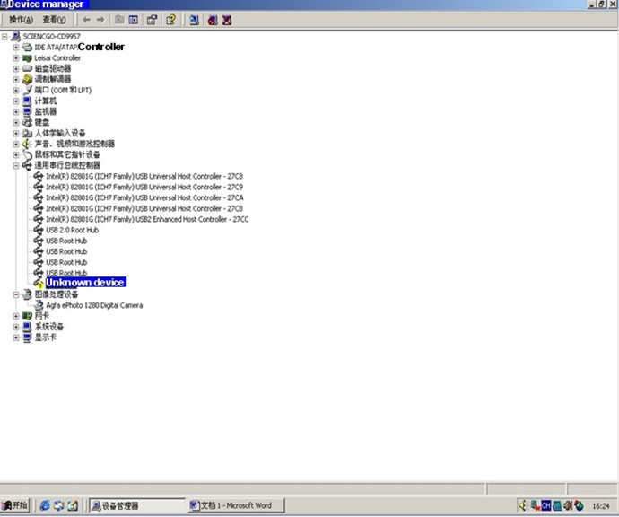


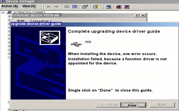
Chapter 7 Machine Circuit Schematic
1 .Circuit wiring diagram
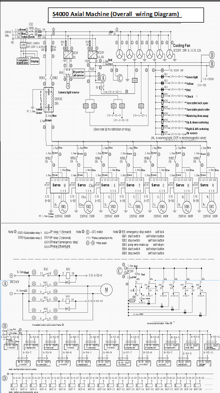
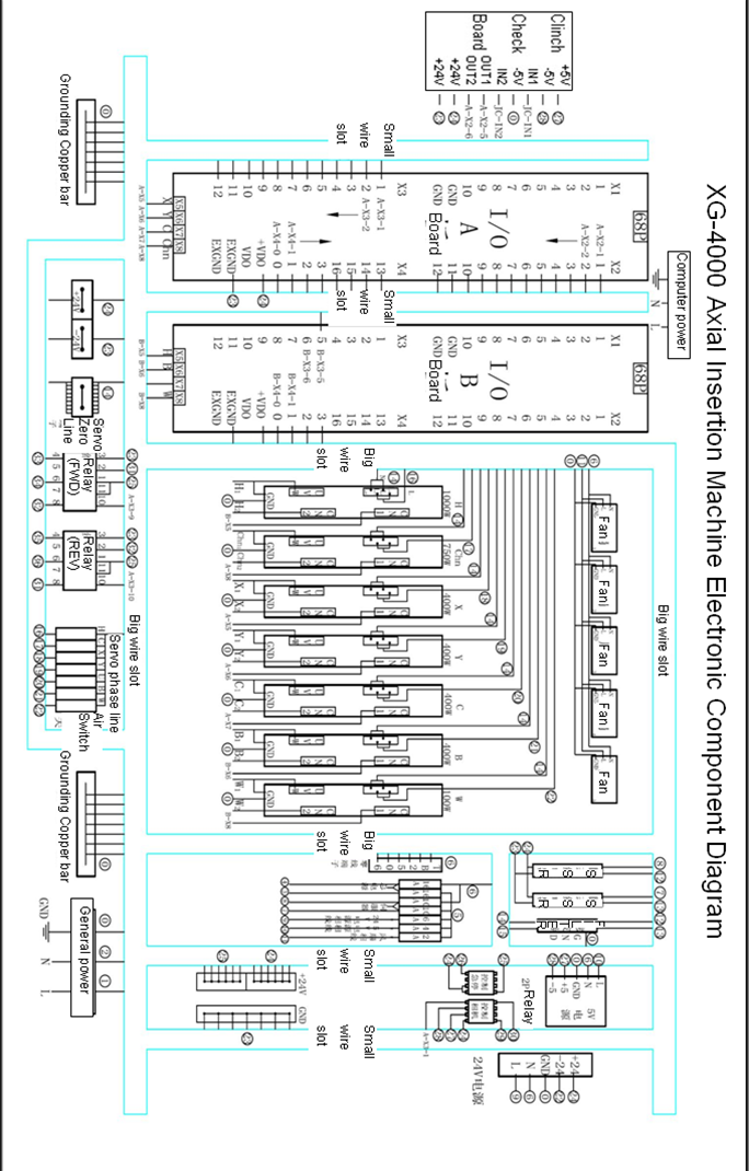
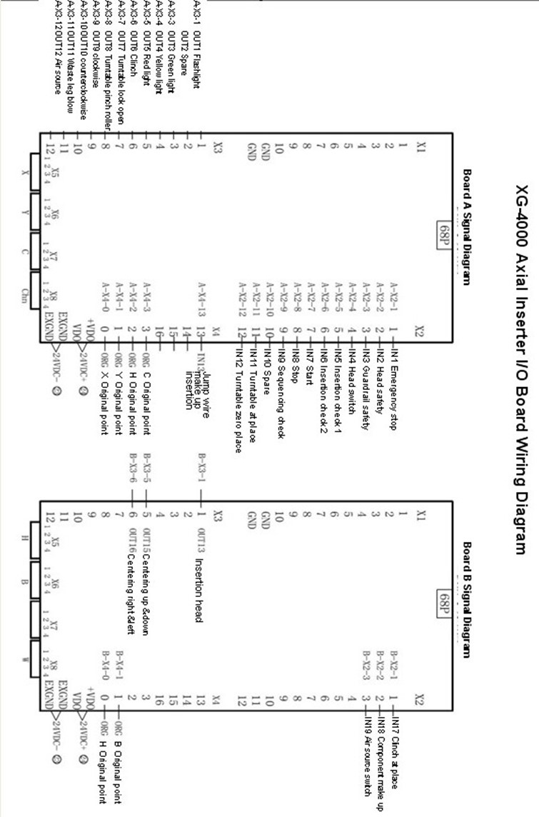
三.I/O A board signal comparison chart 1
| I/O A board wire connection chart | |||||
| Interface board |
Signal mark |
Signal name |
Interface board |
Signal mark |
Signal name |
| 1 |
35 |
PULC+ |
C servo X5–3 |
||
| 2 |
PULX+ |
X servo X5—3 |
36 |
PULC- |
C servo X5–4 |
| 3 |
PULX- |
X servo X5—4 |
37 |
DIRC+ |
C servo X5–5 |
| 4 |
DIRX+ |
X servo X5—5 |
38 |
DIRC- |
C servo X5–6 |
| 5 |
DIRX- |
X servo X5—6 |
39 |
PULChn1+ |
Chn1 servo X5—3 |
| 6 |
PULY+ |
Y servo X5—3 |
40 |
PULChn1- |
Chn1 servo X5—4 |
| 7 |
PULY- |
Y servo X5—4 |
41 |
DIRChn1+ |
Chn1 servo X5—5 |
| 8 |
DIRY+ |
Y servo X5—5 |
42 |
DIRChn1- |
Chn1 servo X5—6 |
| 9 |
DIRY- |
Y servo X5—6 |
43 |
OUT1 |
Flashlight |
| 10 |
ELX+ |
X+ limit |
44 |
OUT2 |
Spare |
| 11 |
XLX- |
X- limit |
45 |
OUT3 |
green light |
| 12 |
SDX+ |
X+ slow down |
46 |
OUT4 |
Yellow light |
| 13 |
SDX- |
X- slow down |
47 |
OUT5 |
Red light |
| 14 |
ORGX |
X original point |
48 |
OUT6 |
clinch |
| 15 |
ELY+ |
Y+ limit |
49 |
OUT7 |
Turn plate lock open |
| 16 |
XLY- |
Y- limit |
50 |
OUT8 |
Turn plate clamping roller |
| 17 |
SDY+ |
Y+ slow down |
51 |
OUT9 |
Clockwise |
| 18 |
SDY- |
Y- slow down |
52 |
OUT10 |
Counterclockwise |
| 19 |
ORGY |
Y original point |
53 |
OUT11 |
Blow away waste leg |
| 20 |
ELC+ |
C+ limit |
54 |
OUT12 |
Air source |
| 21 |
ELC- |
C- limit |
55 |
IN5 |
insertion inspection 1 |
| 22 |
56 |
IN6 |
insertion inspection 2 |
||
| 23 |
57 |
IN7 |
Start |
||
| 24 |
ORGC |
C original point |
58 |
IN8 |
Stop |
| 25 |
ELXChn1+ |
59 |
IN9 |
sequencer inspection |
|
| 26 |
ELXChn1- |
60 |
IN10 |
||
| 27 |
61 |
IN11 |
Turn plate in place |
||
| 28 |
62 |
IN12 |
Turn plate at zero position |
||
| 29 |
ORHChn1 |
Chn1 original point |
63 |
IN13 |
|
| 30 |
IN1 |
Emergency switch |
64 |
IN14 |
|
| 31 |
IN2 |
Head safety |
65 |
IN15 |
|
| 32 |
IN3 |
Protecting cover safety |
66 |
GND |
24VDC- |
| 33 |
IN4 |
Head switch |
67 |
VDD |
24VDC+ |
| 34 |
GND |
Groundwire |
68 |
IN16 |
|
|
X |
X motor |
||||
|
Y |
Y motor |
||||
|
C |
C motor |
||||
|
Chn1 |
Chn1 motor |
||||
I/O B board signal comparison chart 2
| I/O B board wire connection chart | |||||
| Interface board |
Signal mark |
Signal name |
Interface board |
Signal mark |
Signal name |
| 1 |
35 |
PULChn2+ |
Chn2 servo X5—3 |
||
| 2 |
PULH+ |
H servo X5—3 |
36 |
PULChn2- |
Chn2 servo X5—4 |
| 3 |
PULH- |
H servo X5—4 |
37 |
DIRChn2+ |
Chn2 servo X5—5 |
| 4 |
DIRH+ |
H servo X5—5 |
38 |
DIRChn2- |
Chn2 servo X5—6 |
| 5 |
DIRH- |
H servo X5—6 |
39 |
PULW+ |
W servo X5—3 |
| 6 |
PULB+ |
H servo X5—3 |
40 |
PULW- |
W servo X5—4 |
| 7 |
PULB- |
H servo X5—4 |
41 |
DIRW+ |
W servo X5—5 |
| 8 |
DIRB+ |
H servo X5—5 |
42 |
DIRW- |
W servo X5—6 |
| 9 |
DIRB- |
H servo X5—6 |
43 |
OUT1 |
Servo enabling |
| 10 |
44 |
OUT2 |
|||
| 11 |
45 |
OUT3 |
|||
| 12 |
46 |
OUT4 |
|||
| 13 |
47 |
OUT5 |
|||
| 14 |
ORGC2 |
C2 original point |
48 |
OUT6 |
|
| 15 |
49 |
OUT7 |
|||
| 16 |
50 |
OUT8 |
|||
| 17 |
51 |
OUT9 |
|||
| 18 |
52 |
OUT10 |
|||
| 19 |
ORGB |
B original point |
53 |
OUT11 |
|
| 20 |
54 |
OUT12 |
|||
| 21 |
55 |
IN5 |
|||
| 22 |
56 |
IN6 |
|||
| 23 |
57 |
IN7 |
|||
| 24 |
ORGH |
H original point |
58 |
IN8 |
|
| 25 |
59 |
IN9 |
|||
| 26 |
60 |
IN10 |
|||
| 27 |
61 |
IN11 |
|||
| 28 |
62 |
IN12 |
|||
| 29 |
63 |
IN13 |
|||
| 30 |
IN1 |
64 |
IN14 |
||
| 31 |
IN2 |
65 |
IN15 |
||
| 32 |
IN3 |
66 |
GND |
24VDC- |
|
| 33 |
IN4 |
67 |
GND |
24VDC+ |
|
| 34 |
GND |
Groundwire |
68 |
N16 |
|
|
H |
head motor | ||||
|
B |
housing motor |
||||
|
CHn2 |
feeder motor |
||||
|
W |
Jump wire motor |
||||
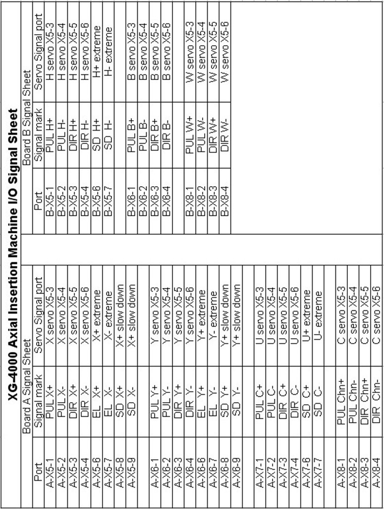

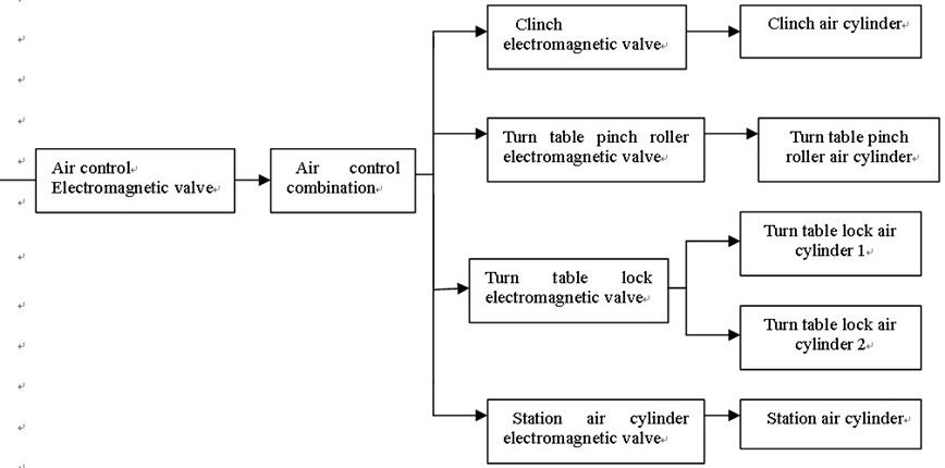
S4000 Pneumetic Connection Chart
2. Computer control chart

Chapter 8 Machinery Break down chart
1.Machinery plane sketch:
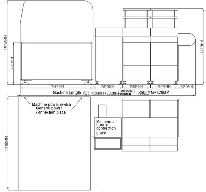
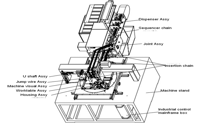
2.Component list
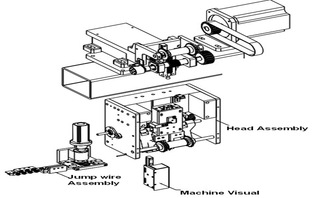
Head Assembly Sketch
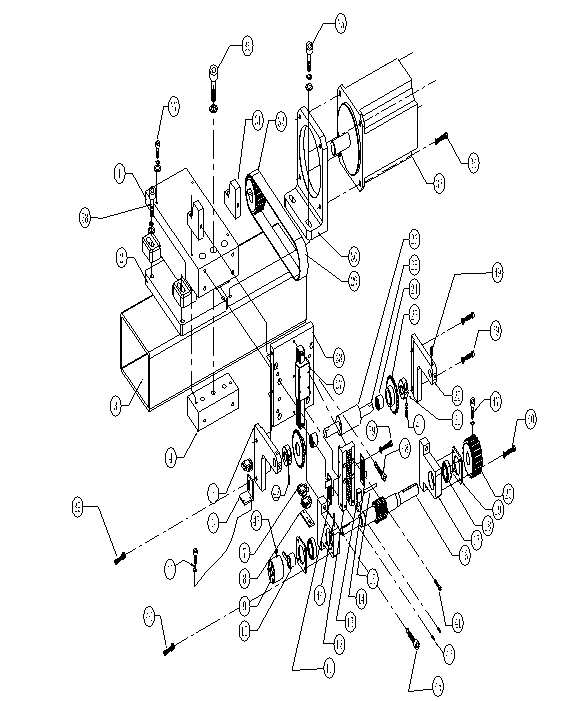
Head Assembly Break down Sketch 1
| Head component list 1 | ||
| No. |
Name |
Part # |
| 1 |
Head stand |
S4000-01-04-001 |
| 2 |
Weld block |
S4000-01-01-014 |
| 3 |
Stand rack (partial) |
S4000-01-01-008 |
| 4 |
Head stand seat pad |
S4000-01-04-072 |
| 5 |
feederchain wheel holder 2 |
S4000-01-11-004 |
| 6 |
Optoelectronic switch holder |
S4000-01-04-016 |
| 7 | ||
| 8 |
H shaft Optoelectronic switch holder |
S4000-01-04-070 |
| 9 |
H shaft adjust wheel |
S4000-01-04-074 |
| 10 |
H shaft zero position spacer |
S4000-01-04-013 |
| 11 |
H shaft detection piece 1 |
S4000-01-04-014 |
| 12 |
H shaft gear rack |
S4000-01-04-007 |
| 13 |
H shaft connector |
S4000-01-04-011 |
| 14 |
H shaft detection piece 2 |
S4000-01-04-071 |
| 15 |
H shaft connecting pin |
S4000-01-04-075 |
| 16 |
H transmitting gear shaft |
S4000-01-04-008 |
| 17 |
H bearing housing |
S4000-01-04-009 |
| 18 |
bearing 6004ZZ |
S4000-01-04-085 |
| 19 |
H bearing cover |
S4000-01-04-010 |
| 20 |
H shaft driven synchronizing wheel |
S4000-01-04-006 |
| 21 |
Anchor ear D14 |
S4000-01-11-036 |
| 22 |
feeder chain wheel housing 1 |
S4000-01-11-003 |
| 23 |
18 toothed chain wheel |
S4000-01-11-014 |
| 24 |
bearing TLA1416 |
S4000-01-11-039 |
| 25 |
feederchain wheel fulcrum bar 2 |
S4000-01-11-007 |
| 26 |
POM bushing 1 |
S4000-01-11-025 |
| 27 |
H shaft liner guide |
S4000-01-04-083 |
| 28 |
H shaft guide rail mounting plate |
S4000-01-04-002 |
| 29 |
Timing belt 240L*28 |
S4000-01-04-084 |
| 30 |
H shaft motor housing |
S4000-01-04-004 |
| 31 |
Fixed housing |
S4000-01-04-003 |
| 32 |
H shaft motor synchronizing wheel |
S4000-01-04-005 |
| 33 |
1000W servo motor |
|
| 34 |
Cup head screw M8×25 |
|
| 35 |
Cup head screw M8×30 |
|
| 36 |
Cup head screw M6×35 |
|
| 37 |
Cup head screw M4×35 |
|
| 38 |
Cup head screw M8×35 |
|
| 39 |
Cup head screw M4×10 |
|
| 40 |
Round head screw M5×12 |
|
| 41 |
Cup head screw M4×12 |
|
| 42 |
Cup head screw M3×20 |
|
| 43 |
set M4×10 |
|
| 44 |
cup head screw M4×12 |
|
| 45 |
cup head screw M6×30 |
|
| 46 |
set M5×10 |
|
| 47 |
cup head screw M5×10 |
|
| 48 |
cup head screw M4×20 |
|
| 49 |
set M5×5 |
|
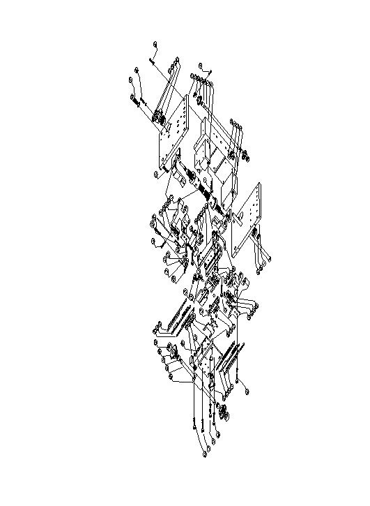 Head Assembly Break down Sketch 2
| Head component list 2 | ||
| No. |
Name |
Part # |
| 1 |
right hand mainbody |
S4000-01-04-021 |
| 2 |
down U shaft lead screw right hand accessory |
S4000-01-04-025 |
| 3 |
right hand long stick |
S4000-01-04-022 |
| 4 |
Optoelectronic switch EE-SX670 |
|
| 5 |
H shaft optoelectronic inspection holder |
S4000-01-04-015 |
| 6 |
left hand long stick |
S4000-01-04-020 |
| 7 |
Head aluminum block |
S4000-01-04-023 |
| 8 |
feederchain wheel fulcrum bar 5 |
S4000-01-11-010 |
| 9 |
bearing BA68ZZ |
S4000-01-11-040 |
| 10 |
10 toothed chaine wheel |
S4000-01-11-033 |
| 11 |
anchor ear |
S4000-01-03-017 |
| 12 |
left hand mainbody |
S4000-01-04-019 |
| 13 | bearing with snap spring 5200ZZ |
S4000-01-04-086 |
| 14 |
U bearing cap |
S4000-01-12-001 |
| 15 |
nut M10*1 |
S4000-01-04-018 |
| 16 |
Locating anchor ear |
S4000-01-04-068 |
| 17 |
U shaft left and right spin lead screw |
S4000-01-04-017 |
| 18 |
low U shaft lead screw left accessory |
S4000-01-04-024 |
| 19 |
left shear stand |
S4000-01-04-026 |
| 20 |
left outer former guide |
S4000-01-04-062 |
| 21 |
feeder pipe |
S4000-01-06-020 |
| 22 |
Left low shear |
S4000-01-04-065 |
| 23 |
Right hand former shear stand |
S4000-01-04-056 |
| 24 |
Right former piece |
S4000-01-04-058 |
| 26 |
left former piece |
S4000-01-04-059 |
| 27 |
left hand former shear stand |
S4000-01-04-057 |
| 28 | locating pin |
S4000-01-04-076 |
| 30 |
LH shear installing cover |
S4000-01-04-061 |
| 31 |
Outer former shear move deep stop block |
S4000-01-04-037 |
| 32 |
spring lamination |
S4000-01-04-054 |
| 33 |
Shim to press spring lamination |
S4000-01-04-053 |
| 34 |
S4000-01-04-031 |
|
| 35 |
ball slot inside shear box |
S4000-01-04-045 |
| 36 |
Shear box anti-dust cover |
S4000-01-04-032 |
| 37 |
Shear box anti-wearing block |
S4000-01-04-035 |
| 38 |
block in shear box |
S4000-01-04-046 |
| 39 |
S4000-01-04-036 |
|
| 40 |
right shear stand |
S4000-01-04-027 |
| 41 |
right outer former guide |
S4000-01-04-063 |
| 42 |
Right low shear |
S4000-01-04-064 |
| 43 |
RH shear installing cover |
S4000-01-04-060 |
| 44 |
Connection head cover |
S4000-01-04-042 |
| 45 |
screw 10-32UNF*1/2 |
S4000-01-04-041 |
| 46 |
ball |
S4000-01-04-044 |
| 47 |
Cross-shaped shear stand |
S4000-01-04-040 |
| 48 |
Block outside shear box |
S4000-01-04-043 |
| 49 |
Outer former limit block |
S4000-01-04-038 |
| 50 |
S4000-01-04-033 |
|
| 51 |
Shear box cover up and down adjustable stand |
S4000-01-04-034 |
| 52 |
left shear |
S4000-01-04-047 |
| 53 |
left outer former |
S4000-01-04-048 |
| 54 |
left pusher tip |
S4000-01-04-049 |
| 55 |
anchor ear D12 |
S4000-01-11-037 |
| 56 |
16 toothed chaine wheel |
S4000-01-11-034 |
| 57 |
Bearing TLA1212 |
S4000-01-11-038 |
| 58 |
feederchain wheel fulcrum bar 1 |
S4000-01-11-006 |
| 59 |
POM bushing 2 |
S4000-01-11-026 |
| 60 |
Press cover on shear cap |
S4000-01-04-039 |
| 61 |
Right pusher tip |
S4000-01-04-050 |
| 62 |
right outer former |
S4000-01-04-051 |
| 63 |
Right shear |
S4000-01-04-052 |
| 64 |
Round bar |
S4000-01-04-028 |
| 65 |
bearing 6200ZZ |
S4000-01-04-087 |
| 66 |
cup head screw M5×25 |
|
| 67 |
cup head screw M4×6 |
|
| 68 |
cup head screw M5×38 |
|
| 69 |
cup head screw M10×30 |
|
| 70 |
cup head screw M5×20 |
|
| 71 |
cup head screw M5×12 |
|
| 72 |
cup head screw M5×16 |
|
| 73 |
cup head screw M3×10 |
|
| 74 |
Cotter Φ5.3 |
|
| 75 |
Locating stud M5×254 |
|
| 76 |
cup head screw M5×6 |
|
| 77 |
cup head screw M5×13 |
|
| 78 |
cup head screw M5×10 |
|
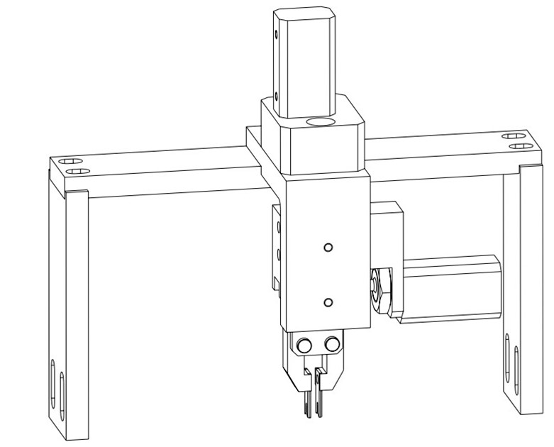
Centering Assembly Picture
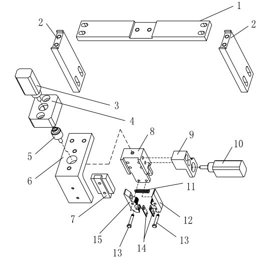
Centering Assembly Break down chart
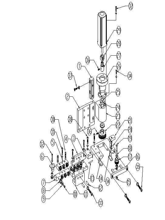
Jump wire box Assembly break down chart
| Jump wire Assembly component list | ||
| No. |
Name |
Part # |
| 1 |
jump wire box alumnium block 5 |
S4000-01-06-045 |
| 2 |
jump wire box alumnium block 1 |
S4000-01-06-041 |
| 3 |
jump wire conditioning(straight) device connecting block |
S4000-01-06-034 |
| 4 |
S4000-01-06-038 |
|
| 5 |
Roller seat 2 |
S4000-01-06-039 |
| 6 |
Roller seat 4 |
S4000-01-06-040 |
| 7 |
Roller locating bloc |
S4000-01-06-033 |
| 8 |
Small wheel |
S4000-01-06-018 |
| 9 |
bearing 684Z |
S4000-01-06-061 |
| 10 |
roller screw |
S4000-01-06-037 |
| 11 |
Roller seat 3 |
S4000-01-06-036 |
| 12 |
Locating stud |
S4000-01-06-031 |
| 13 |
jump wire pipe |
S4000-01-06-032 |
| 14 |
Shield piece |
S4000-01-06-047 |
| 15 |
3/16 loose-proof nut |
S4000-03-06-014 |
| 16 |
jump wire box alumnium block 4 |
S4000-01-06-044 |
| 17 |
jump wire gear 2 |
S4000-01-06-049 |
| 18 |
bearing MF105ZZ |
S4000-01-06-062 |
| 19 |
gear tighten screw |
S4000-01-06-053 |
| 20 |
jump wire box alumnium block 3 |
S4000-01-06-043 |
| 21 |
alumnium block 2 |
S4000-01-06-052 |
| 22 |
jump wire gear 1 |
S4000-01-06-050 |
| 23 |
jump wire box alumnium block 2 |
S4000-01-06-042 |
| 24 |
bearing F699ZZ |
S4000-01-06-063 |
| 25 |
jump wire box main shaft |
S4000-01-06-046 |
| 26 |
feed motor housing |
S4000-01-06-028 |
| 27 |
feed motor connector |
S4000-01-06-027 |
| 28 |
feed motor connector anchor ear |
S4000-01-06-026 |
| 29 |
100W servo motor |
|
| 30 |
jump wire spring |
S4000-01-06-030 |
| 31 |
cup head screw M5×20 |
|
| 32 |
round cup screw M4×12 |
|
| 33 |
round cup screw M4×10 |
|
| 34 |
cup head screw M4×12 |
|
| 35 |
set M4×5 |
|
| 36 |
cup head screw M5×25 |
|
| 37 |
round cup screw M5×20 |
|
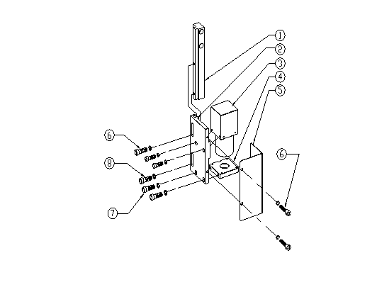
Machine Visual break down chart
| Machine Visual component list | ||
| No. |
Name |
Part # |
| 1 |
camera stand up and down adjusting guide rail |
S4000-01-13-001 |
| 2 |
camera stand |
S4000-01-13-002 |
| 3 |
camera |
S4000-01-13-006 |
| 4 |
camera flashlight stand |
S4000-01-13-003 |
| 5 |
camera cover |
S4000-01-13-004 |
| 6 |
round cup screw M4×10 |
|
| 7 |
round cup screw M5×16 |
|
| 8 |
cup head screw M3×12 |
|
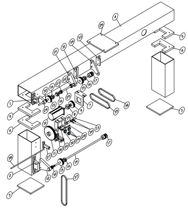
C Shaft Assembly Break down chart
| U shaft Assembly component list | ||
| No. |
Name |
Part # |
| 3 |
Machine stand seat pad 3 |
S4000-01-01-022 |
| 4 |
Machine stand big square tube |
S4000-01-01-008 |
| 5 |
Machine stand big square tube seat pad1 |
S4000-01-01-012 |
| 6 |
Machine stand big square tube seat pad2 |
S4000-01-01-013 |
| 7 |
X shaft motor houisng |
S4000-01-02-036 |
| 8 |
XY motor synchronizing wheel anchor ear |
S4000-01-02-037 |
| 9 |
U motor synchronizing wheel |
S4000-01-02-023 |
| 10 |
400W servo motor |
|
| 11 |
U zero position synchronizing wheel |
S4000-01-03-002 |
| 12 |
Low U stand |
S4000-01-03-005 |
| 13 |
U zero position bar |
S4000-01-03-016 |
| 14 |
low U connecting rod |
S4000-01-03-006 |
| 15 |
synchronizing wheel D10 |
S4000-01-03-008 |
| 16 |
anchor ear D14 |
S4000-01-03-009 |
| 17 |
Shaft joint |
S4000-01-03-020 |
| 18 |
U zero position synchronizing wheel housing |
S4000-01-03-014 |
| 19 |
U zero position bar locating anchor ear |
S4000-01-03-017 |
| 20 |
U zero position limit piece |
S4000-01-03-018 |
| 21 |
up U right hand stand |
S4000-01-03-010 |
| 22 |
Bearing 608ZZ |
S4000-01-03-025 |
| 23 |
U zero position driving synchronizing wheel |
S4000-01-03-003 |
| 24 |
up U left hand stand |
S4000-01-03-013 |
| 25 |
up U connecting rod |
S4000-01-03-006 |
| 26 |
Head seat pad |
S4000-01-01-014 |
| 27 |
jump wire pipe housing |
S4000-01-06-025 |
| 28 |
U zero position switch holder |
S4000-01-03-015 |
| 29 |
optoelectronic switchEE-SX670 |
|
| 30 |
Bearing BA66Z |
S4000-01-03-024 |
| 31 |
up U right hand stand housing |
S4000-01-03-011 |
| 32 |
Bearing 608ZZ |
S4000-01-03-025 |
| 34 |
U zero position limit piece |
S4000-01-03-019 |
| 35 |
timing belt 180XL*10 |
S4000-01-03-022 |
| 36 |
timing belt 150XL*10 |
S4000-01-03-021 |
| 37 |
timing belt 270XL*10 |
S4000-01-03-023 |
| 38 |
feed pipe φ6*φ5*500 |
S4000-01-06-054 |
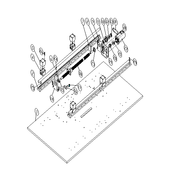
Workbench X Assembly Break down chart
| Workbench X Assembly component list | ||
| No. |
Name |
Part # |
| 1 |
baseboard |
S4000-01-01-005 |
| 2 |
X rail holder |
S4000-01-02-014 |
| 4 |
Slider bearing |
S4000-01-02-041 |
| 5 |
X sliderseat pad |
S4000-01-02-024 |
| 6 |
XY rail |
S4000-01-02-012 |
| 7 |
X impact-proof stop block |
S4000-01-02-008 |
| 9 |
X bearing housing1 |
S4000-01-02-015 |
| 10 |
XY bearing cap |
S4000-01-02-027 |
| 11 |
Bearing 7202CYP4 |
S4000-01-02-042 |
| 12 |
XY lead screw synchronizing wheel anchor ear |
S4000-01-02-021 |
| 13 |
XY lead screw synchronizing wheel |
S4000-01-02-022 |
| 14 |
X bearing housing 2 |
S4000-01-02-019 |
| 15 |
bearing 6202ZZ |
S4000-01-02-043 |
| 16 |
XY zero position limit housing |
S4000-01-02-026 |
| 17 |
Optoelectronic switch EE-SX670 |
|
| 18 |
XY shaft lead screw |
S4000-01-02-035 |
| 19 |
X shaft motor housing |
S4000-01-02-036 |
| 20 |
XY motor synchronizing wheel |
S4000-01-02-023 |
| 21 |
XY motor synchronizing wheel anchor ear |
S4000-01-02-037 |
| 22 |
400W servo motor |
|
| 23 |
lead screw nut |
S4000-01-02-028 |
| 24 |
cup head screw M6×25 |
|
| 25 |
cup head screw M5×25 |
|
| 26 |
cup head screw M6×35 |
|
| 27 |
cup head screw M12×35 |
|
| 28 |
cup head screw M5×16 |
|
| 29 |
cup head screw M5×5 |
|
| 30 |
cup head screw M4×20 |
|

Housing Assembly Picture
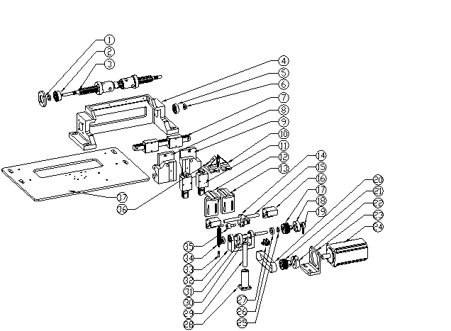 Housing Assembly Break down Chart
| housing component list | ||
| No. |
Name |
Part # |
| 1 |
U bearing cap |
S4000-01-12-001 |
| 2 |
bearing with snap spring |
5200ZZ |
| 3 |
U shaft left and right spin lead screw |
S4000-01-04-017 |
| 4 |
housing frame |
S4000-01-12-002 |
| 5 |
bearing |
6200ZZ |
| 6 |
lead screw nut |
S4000-01-04-018 |
| 7 |
Long straight liner guide rail |
S4000-01-12-053 |
| 8 |
LH aluminum block fixed on lead screw |
S4000-01-12-013 |
| 9 |
RH aluminum block fixed on lead screw |
S4000-01-12-012 |
| 10 |
RH clinch housing |
S4000-01-12-003 |
| 11 |
Short straight liner guide rail |
S4000-01-12-054 |
| 12 |
LH clinch seat |
S4000-01-12-005 |
| 13 |
RH clinch seat |
S4000-01-12-006 |
| 14 |
Hard steel shaft fixed seat |
S4000-01-12-038 |
| 15 |
Clinch up and down slider bar |
S4000-01-12-011 |
| 16 |
slider to locate clinch |
S4000-01-12-009 |
| 17 |
housing driven synchronizing wheel |
S4000-01-12-036 |
| 18 |
anchor ear D12 |
S4000-01-12-037 |
| 19 |
housing inspection piece |
S4000-01-12-042 |
| 20 |
timing belt |
116XL*12 |
| 21 |
housing motor synchronizing wheel |
S4000-01-12-039 |
| 22 |
400W motor synchronizing wheel anchor ear |
S4000-01-02-037 |
| 23 |
housing motor synchronizing wheel |
S4000-01-12-039 |
| 24 |
400W servo motor |
MHMD042P1U |
| 25 |
nut M10*1 |
S4000-01-12-043 |
| 26 |
bearing |
6900ZZ |
| 27 |
optoelectronic switch |
EE-SX671 |
| 28 |
Straight line bearing |
LMK13LUU |
| 29 |
Hard steel shaft |
S4000-01-12-052 |
| 30 |
housing cam shaft |
S4000-01-12-033 |
| 31 |
housing cam |
S4000-01-12-034 |
| 32 |
housing cam shaft housing |
S4000-01-12-032 |
| 33 |
Spring hanging |
S4000-01-12-040 |
| 34 |
SPRING |
S4000-01-12-044 |
| 35 |
bearing |
CR10-1 |
| 36 |
LH clinch housing |
S4000-01-12-004 |
| 37 |
housing frame seat pad |
S4000-01-12-031 |

Clinch Break down Chart
| Clinch component list | ||
| No. |
Name |
Part # |
| 1 |
Piston travel limit tighten nut |
S4000-01-12-023 |
| 2 |
piston travel limit block |
S4000-01-12-019 |
| 3 |
inner buffering glue |
S4000-01-12-025 |
| 4 |
clinch air cylinder cap |
S4000-01-12-015 |
| 5 |
seal ring φ7.5*1.8 |
|
| 6 |
seal ring φ31.5*1.8 |
|
| 7 |
piston rod |
S4000-01-12-020 |
| 8 |
piston nut |
S4000-01-12-021 |
| 9 |
piston |
S4000-01-12-022 |
| 10 |
seal ring φ28*3.55 |
|
| 11 |
seal ring φ12.2*2.65 |
|
| 12 |
clinch air cylinder |
S4000-01-12-014 |
| 13 |
Elasticity cylindrical pin ¢3.2 |
S4000-01-12-056 |
| 14 |
elasticity cylindrical pin ¢1.6 |
S4000-01-12-055 |
| 15 |
Triangle shear cover |
S4000-01-12-016 |
| 16 |
Movable shear |
S4000-01-12-017 |
| 17 |
Triangle shear cover |
S4000-01-12-018 |
| 18 |
S4000-01-12-008 |
|
| 19 |
Cap to press on debris dispose pipe |
S4000-01-12-024 |
| 20 |
seal ring φ5*2 |
|
| 21 |
Air connector PC06-01 |
|
| 22 |
cup head screw M4×16 |
|
| 23 |
cup head screw M3×10 |
|
| 24 |
flat head screw M3×8 |
|
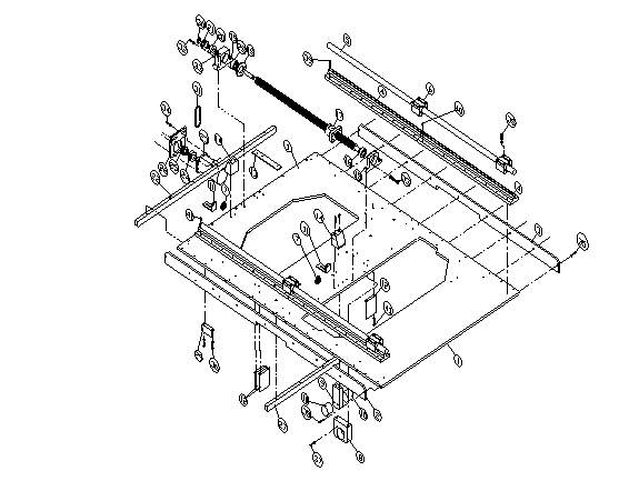
Workbench Y Assembly Break down chart
| Workbench Y Assembly component list | ||
| No. |
Name |
Part # |
| 1 |
workbench middle aluminium plate |
S4000-01-02-002 |
| 2 |
left hand flatten alumnium stick |
S4000-01-02-005 |
| 3 |
right hand flatten alumnium stick |
S4000-01-02-006 |
| 4 |
Y rail housing |
S4000-01-02-013 |
| 5 |
XY rail hard steel shaft |
S4000-01-02-012 |
| 6 |
Slider bearing |
S4000-01-02-041 |
| 7 |
Optoelectronic switch EE-SX670 |
|
| 8 |
Yshaft nut locating seat |
S4000-01-02-020 |
| 9 |
Y impact-proof locating block |
S4000-01-02-007 |
| 10 |
impact-proof rubber |
|
| 11 |
X.Y zero position limit seat |
S4000-01-02-026 |
| 12 |
Y limit switch piece |
S4000-01-02-030 |
| 13 |
Y drag chain installing board |
S4000-01-02-029 |
| 14 |
Y impact-proof stop block |
S4000-01-02-010 |
| 15 |
Y bearing housing1 |
S4000-01-02-018 |
| 16 |
Bearing 7202CYP4 |
S4000-01-02-042 |
| 17 |
XY lead screw |
S4000-01-02-035 |
| 18 |
XY bearing cap |
S4000-01-02-027 |
| 19 |
Y bearing housing2 |
S4000-01-02-019 |
| 12 |
XY lead screw synchronizing wheel anchor ear |
S4000-01-02-021 |
| 21 |
XY lead screw synchronizing wheel |
S4000-01-02-022 |
| 22 |
Rear flatten alumnium stick |
S4000-01-02-004 |
| 23 |
400W servo motor |
|
| 21 |
XY motor synchronizing wheel anchor ear |
S4000-01-02-037 |
| 25 |
XY motor synchronizing wheel |
S4000-01-02-023 |
| 26 |
Y shaft motor housing |
S4000-01-02-036 |
| 27 |
Middle flatten alumnium stick |
S4000-01-02-003 |
| 28 |
bearing 6200ZZ |
S4000-01-02-043 |
| 29 |
Y limit switch piece |
S4000-01-02-031 |
| 30 |
nut M14X1 |
S4000-01-02-028 |
| 31 |
timing belt 161L*10 |
S4000-01-02-044 |
| 32 |
cup head screw M4×20 |
|
| 33 |
cup head screw M4×25 |
|
| 34 |
cup head screw M4×16 |
|
| 35 |
round head screw M5×12 |
|
| 36 |
round head screw M5×10 |
|
| 37 |
cup head screw M5×16 |
|
| 38 |
cup head screw M6×35 |
|
| 39 |
round head screw M5×25 |
|
| 40 |
Locating pin 3/16″×20 |
|
| 41 |
cup head screw M5×5 |
|
 Workbench Board and turn plateMechanism break down chart
| workbench board and turn plateMechanism component list | ||
| No. |
Name |
Part # |
| 1 |
Workbench |
S4000-01-07-001 |
| 2 |
workbench rear aluminum bar |
S4000-01-07-004 |
| 3 |
workbench RH alumnium bar |
S4000-01-07-002 |
| 4 |
turn table motor housing |
S4000-01-07-023 |
| 5 |
turn table motor belt wheel XL16 |
S4000-01-07-036 |
| 6 |
bearing F606ZZ |
S4000-01-07-056 |
| 8 |
turn table driver belt wheel XL16 |
S4000-01-07-037 |
| 9 | turn table air cylinder install alumnium block |
S4000-01-07-005 |
| 11 |
workbench LH flatten alumnium stick |
S4000-01-07-003 |
| 12 |
Y impact-proof locating block |
S4000-01-02-009 |
| 13 |
impact-proof rubber |
S4000-01-02-045 |
| 15 |
Y shaft nut locating seat |
S4000-01-02-017 |
| 16 |
turn table motor |
|
| 17 |
round turn plate |
S4000-01-07-006 |
| 18 |
turn plate lock ejector rod |
S4000-01-07-008 |
| 19 |
turn plate lock mainblock |
S4000-01-07-009 |
| 20 |
RH turn plate stop locking |
S4000-01-07-010 |
| 21 |
LH turn plate stop locking |
S4000-01-07-011 |
| 22 |
turn plate stop locking baffle block |
S4000-01-07-012 |
| 23 |
turn plate stop locking block PIN |
S4000-01-07-013 |
| 24 |
turn plate stop locking installing PIN |
S4000-01-07-014 |
| 25 |
SPRING |
S4000-01-07-015 |
| 26 |
lock elastic bolt cover |
S4000-01-07-016 |
| 27 |
lock air cylinder connector |
S4000-01-07-017 |
| 28 |
SPRING |
S4000-01-07-018 |
| 29 |
turn table driving wheel axle |
S4000-01-07-019 |
| 30 |
turn table driving wheel socket |
S4000-01-07-020 |
| 31 |
turn table driving wheel stand slider |
S4000-01-07-021 |
| 32 |
turn table driving wheel stand slider cover |
S4000-01-07-022 |
| 33 |
turn plate driving air cylinder |
S4000-05-01-013 |
| 34 |
turn table lock air cylinder housing |
S4000-01-07-025 |
| 35 |
platy bearing φ6.35*φ17.02 |
S4000-01-07-052 |
| 36 |
turn table lock clamp |
S4000-01-07-027 |
| 37 |
turn table locaitng piece for four corners |
S4000-01-07-028 |
| 38 |
turn table locating sensor seat |
S4000-01-07-029 |
| 39 |
turn table jig locating PIN |
S4000-01-07-030 |
| 40 |
turn table lock air cylinder |
S4000-01-07-025 |
| 41 |
turn table locaitng bearing for four corners |
S4000-01-07-032 |
| 42 |
turn table rotate rail bearing housing |
S4000-01-07-033 |
| 43 |
bearing CR12 |
S4000-01-07-054 |
| 44 |
Bearing CR10-1 |
S4000-01-07-055 |
| 45 |
turn table lock device cover |
S4000-01-07-034 |
| 46 |
turn plate electromagnetic valve |
S4000-05-01-007 |
| 50 |
magnet |
S4000-01-07-051 |
| 51 |
driving synchronizing wheel rubber |
S4000-01-07-031 |
| 52 |
D6.35 anchor ear |
S4000-01-07-026 |
| 53 |
PIN to connect and lock air cylinder |
S4000-01-07-035 |
| 54 |
Air connector PC06-M5 |
|
| 55 |
Air connector PC04-M5 |
|
| 56 |
Air connector PC04-M3 |
|
| 57 |
cup head screw M6×20 |
|
| 58 |
cup head screw M5×20 |
|
| 59 |
cup head screw M5×10 |
|
| 60 |
Cup head screw M4×8 |
|
| 61 |
cup head screw M6×25 |
|
| 62 |
cup head screw M4×10 |
|
| 63 |
cup head screw M5×25 |
|
| 64 |
cup head screw M3×25 |
|
| 65 |
round cup screw M5×20 |
|
| 66 |
cup head screw M4×12 |
|
|
1 |
Carrier clmap shaft |
S4000-01-10-005 |
|
2 |
Right hand carrier clmap |
S4000-01-10-002 |
|
3 |
left hand carrier clmap |
S4000-01-10-003 |
|
4 |
carrier clmap piece |
S4000-01-10-004 |
|
5 |
carrier clmap spring |
S4000-01-10-006 |
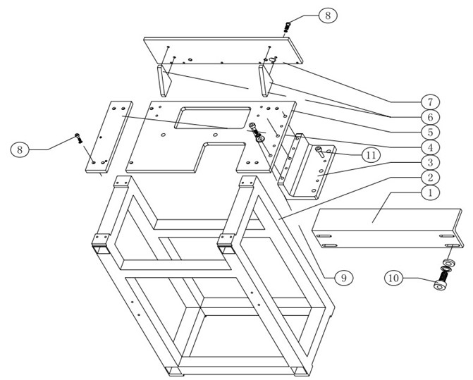 Conjunction break down chart 一
| Conjunction component list 1 | ||
| No. |
Name |
Part # |
| 1 |
motor holding stand |
S4000-02-02-008 |
| 2 |
Butt joint machine stand |
S4000-02-01-005 |
| 3 |
Butt joint connecting board |
S4000-02-01-014 |
| 4 |
Machine stand connecting block |
S4000-02-01-003 |
| 5 |
Connection baseboard |
S4000-02-01-001 |
| 6 |
Right angle locating seat |
S4000-02-01-004 |
| 7 | connect panel |
S4000-02-01-002 |
| 8 |
cup head screw M6×20 |
|
| 9 |
cup head screw M8×35 |
|
| 10 |
cup head screw M10×80 |
|
| 11 |
Locating pin |
S4000-02-01-016 |

Conjunction Break down picture 2
| Conjunction component list 2 | ||
| No. |
Name |
Part # |
| 1 |
750W servo motor |
|
| 2 | Planetary speed reducer |
DH090L1-10-19-70 |
| 3 |
750W motor holdering |
S4000-02-02-011 |
| 4 |
shaft joint |
LK11-68K-20.64-20 |
| 5 |
Driving sprocket shaft |
S4000-02-02-013 |
| 6 |
Driving synchronizing wheel |
S4000-02-02-007 |
| 7 |
40 toothed chaine wheel |
S4000-02-03-009 |
| 8 |
Carrier clamp open wheel |
S4000-02-03-008 |
| 9 |
H shaft optoelectronic inspection holder2 |
S4000-01-04-015 |
| 10 |
optoelectronic switchEE-SX671 |
|
| 11 |
10 toothed inspection plate |
S4000-02-02-026 |
| 12 |
Rear aluminium plate |
S4000-02-02-001 |
| 13 |
bearing BA1310ZZ |
S4000-02-02-045 |
| 14 |
Rear clapboard 2 |
S4000-02-02-003 |
| 15 |
front aluminium plate |
S4000-02-02-004 |
| 16 |
Waste leg hopper |
S4000-03-08-029 |
| 17 |
Front clapboard 2 |
S4000-02-02-039 |
| 18 |
Front clapboard 1 |
S4000-02-02-038 |
| 19 |
Baffle board for waste material |
S4000-02-02-041 |
| 20 |
Shaft locating board |
S4000-02-02-037 |
| 21 |
Front spacer column |
S4000-02-02-040 |
| 22 |
material pressing piece left hand installation block |
S4000-02-05-011 |
| 23 | spacer block |
S4000-02-05-012 |
| 24 |
arched material pressing piece |
S4000-02-05-003 |
| 25 |
seat pad |
S4000-02-05-016 |
| 26 |
material pressing piece locating holder |
S4000-02-05-017 |
| 27 |
material shielder installation block |
S4000-02-04-004 |
| 28 |
Left hand baffle piece |
S4000-02-04-001 |
| 29 |
material pressing piece right hand installation block |
S4000-02-05-019 |
| 30 | right hand baffle piece |
S4000-02-04-002 |
| 31 |
Rear clapboard 1 |
S4000-02-02-002 |
| 32 |
Rear ear |
S4000-02-02-005 |
| 33 |
Locating block to tighten timing belt |
S4000-02-02-033 |
| 34 |
Adjustable block to tighten timing belt |
S4000-02-02-034 |
| 35 |
bearing TLA1010Z |
S4000-02-02-046 |
| 36 |
aluminium column |
S4000-02-02-036 |
| 37 |
Headed ejection pin φ10*104 |
S4000-02-02-035 |
| 38 |
Timing belt HTD520-5M*28 |
S4000-02-02-044 |
| 39 |
synchronizing wheel locating holder |
S4000-02-02-029 |
| 40 |
Driven sprokect wheel shaft |
S4000-02-02-014 |
| 41 |
driven synchronizing wheel |
S4000-02-02-006 |
| 42 |
material catching wheel |
S4000-02-03-003 |
| 43 |
36 toothed chaine wheel |
S4000-02-02-015 |

Partial picture of Sequencer
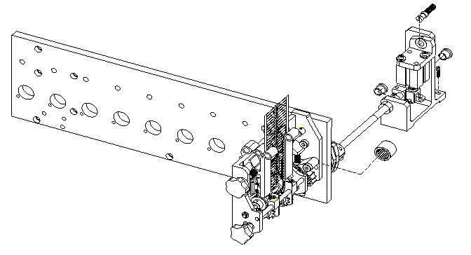
Dispenser Driving Assembly picture 1
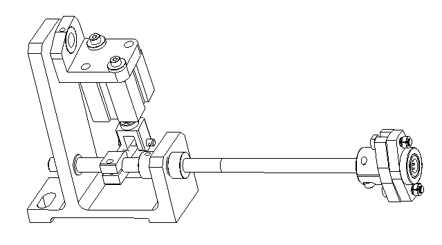
Dispenser Driving Assembly picture 2

Dispenser Driving Assembly Break down chart
| Dispenser Driving Assembly component list | ||
| No. |
Name |
Part # |
| 1 |
air cylinder install housing |
S4000-03-06-001 |
| 2 |
air cylinder connecting rod |
S4000-03-06-010 |
| 3 |
air cylinder shaft anchor ear |
S4000-03-06-007 |
| 4 |
Station coupling pin |
S4000-03-06-006 |
| 5 |
station shaft joint 1 |
S4000-03-06-004 |
| 6 |
Uni-directional bearing RC-061008 |
S4000-03-06-013 |
| 7 |
station shaft joint 2 |
S4000-03-06-005 |
| 8 |
short air cylinder shaft |
S4000-03-06-002 |
| 9 |
air cylinder connecting rod pin |
S4000-03-06-012 |
| 10 |
air cylinder connector |
S4000-03-06-011 |
| 11 |
air cylinder |
|
| 12 |
air cylinder install right angle housing |
S4000-03-06-008 |
| 13 |
Steel bushing |
S4000-03-06-009 |
| 43 |
Loose-proff nut |
S4000-03-06-014 |
| 44 |
1MM bolt |
S4000-03-06-016 |
| 45 |
cup head screw M8*20 |
|
| 46 |
cup head screw M5*25 |
|
| 47 |
cup head screw M6*25 |
|
| 48 |
nut M8 |
|
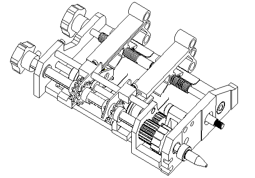
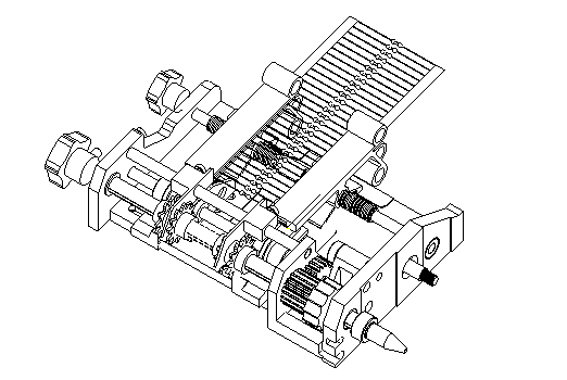

Picture of Dispenser

Dispenser Break down chart
| Dispenser component list | ||
| No. |
Name |
Part # |
| 1 |
Station body |
S4000-03-05-001 |
| 2 |
S4000-03-05-024 |
|
| 3 |
inner component glue track |
S4000-03-05-031 |
|
outer component glue track |
S4000-03-05-032 |
|
| 4 |
Station maine driver rod |
S4000-03-05-023 |
| 5 |
Station driven rod |
S4000-03-05-026 |
| 6 |
left hand station component gear |
S4000-03-05-003 |
|
right hand station component gear |
S4000-03-05-004 |
|
| 8 |
flanged shaft sleeve |
S4000-03-05-027 |
| 9 |
Prositive and reverse thread stem |
S4000-03-05-021 |
| 10 |
guide rail gear outside station |
S4000-03-05-005 |
|
inner guide rail gear inside station |
S4000-03-05-006 |
|
| 11 |
outer gear shear |
S4000-03-05-008 |
|
inner gear shear |
S4000-03-05-007 |
|
| 12 |
Feed parallel wheel |
S4000-03-05-002 |
| 13 |
Driven gear |
S4000-03-05-010 |
| 14 |
Front stainless steel bend rail fulcrum bar |
S4000-03-05-025 |
| 15 |
Front inner stainless steel bend rail |
S4000-03-05-013 |
|
Front outer stainless steel bend rail |
S4000-03-05-014 |
|
| 16 |
Space spring |
S4000-03-05-028 |
| 17 |
stop body |
S4000-03-05-020 |
| 18 |
Station outer shear |
S4000-03-05-011 |
|
Station innershear |
S4000-03-05-012 |
|
| 19 |
anchor ear |
S4000-03-05-036 |
| 20 |
Main driving gear |
S4000-03-05-009 |
| 21 |
Rear outer bend rail |
S4000-03-05-015 |
|
Rear inner bend rail |
S4000-03-05-016 |
|
| 22 |
stop pulley |
S4000-03-05-019 |
| 23 |
Stop spring |
S4000-03-05-037 |
| 24 |
Stop body locating bolt |
S4000-03-05-017 |
| 25 |
Short rubber cover |
S4000-03-05-034 |
| 26 |
Station main driver rod stem |
S4000-03-05-022 |
| 27 |
Rear stainless steel guide rail lock plate |
S4000-03-05-030 |
| 28 |
Station shear seat pad |
S4000-03-05-029 |
| 29 |
Long rubber cover |
S4000-03-05-035 |
| 30 |
set screw M3*5 |
|
| 31 |
cup head screw M4*12 |
|
| 32 |
set screw M4*5 |
|
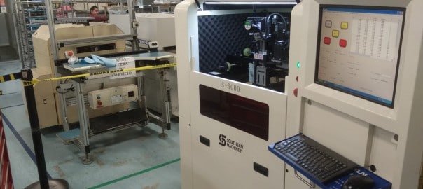
[Canvasio3DPro templateID=”7″ objectID=”5″][/Canvasio3DPro]
[Canvasio3DPro templateID=”6″ objectID=”4″][/Canvasio3DPro]
[Canvasio3DPro templateID=”5″ objectID=”3″][/Canvasio3DPro]
[Canvasio3DPro templateID=”8″ objectID=”1″][/Canvasio3DPro]

Stay ahead of PCB Manufacturing! The digital curve is constantly bending toward demands for digital devices with increased capabilities and FASTER availability. By using the equipment you already own, you can improve upon its capabilities to meet these growing demands. We will use your current Universal Insertion Machine’s capabilities to transition it to an Automatic Board Handling System that will speed up processes and accomplish maximum PCB production successfully.
We at Southern Machinery have the solution to your distinct Automatic Board Handling needs. Whether you require Magazine-to-Magazine Configuration, Destacker/Conveyor-to-Magazine Loader Configuration, or In-line Configuration, we can serve to improve your PCB assembly line.


 After many requests, we are thrilled to announce our Industry Leader Newsletter. As an Industry Leader, Southern Machinery wants to provide your company with the same excellence we put into our equipment and services. We know your job is important and you must always stay ahead of trends in PCB Assembly. Changes in labor costs, shifting environmental laws and policies, energy conservation efforts, advancing industries, international trade politics, etc., are causing a reemergence of in-house manufacturing systems to be put into place. The tide has shifted and it is now time to begin transitioning to a more self-sufficient manufacturing system.
Welcome to our smthelp.net Newsletter! No matter what your company role is, this Newsletter will keep you up-to-date with the most important topics and events that affect the quality and profitability of your manufacturing systems. If it has been a while since we last spoke, stay tuned! We will be delivering important PCB topics to your inbox. In the meantime, we have put a quality checklist together for you!
Your Manufacturing Quality Checklist here:
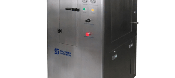
After the PCB is completed, the electric elements ought to be attached in order that a functional PCB assembly is formed. There are two construction processes which can be utilized to be able to type the PCB assembly. One could be the through-hole building in which the component leads are inserted within the holes although the other one may be the surface-mount building wherein the components are situated on pads positioned around the external surfaces on the PCB. Each sorts of construction have element leads that are fixed mechanically also as electrically towards the board through a metal solder which has melted.
Additionally, you’ll find a variety of soldering solutions to become utilized as a way to connect the PCB elements to ensure that PCB assembly could be achievable.
Production that is definitely of higher volume have to be carried out by means of machine placement and bulk wave sort of soldering. Having said that, expert technicians possess the capability to solder incredibly minute parts by the hand beneath a microscope. This is typically completed together with the use of tweezers and a soldering iron with a fine tip which is made for compact volume prototypes. Yet, there are parts that are impossible to solder together with the hands just like the ball grid array.
Visit PCB auto to know more about
PCB’s which would make up the PCB assembly have conformal coating that is certainly applied by way of dipping or spraying once the elements are carried out soldering. This coat will generally protect against corrosion plus the leaking of present or achievable shorting because of condensation. PCB assembly is static sensitive, thereby; it should be placed inside antistatic bags although it can be becoming transported. Improper techniques in handling could transmit static charge by way of the board and because of this may well damage the elements.


Waste Streams from Printed Circuit Board Manufacturing
Waste Stream Waste Stream
Waste Source Description Composition
Cleaning/Surface preparation 1. Airborne particulates
2. Acid fumes/organic vapors
3. Spent acid/alkaline solution
4. Spent halogenated solvents
5. Waste rinse water
Catalyst application/
Electroless plating
1. Spent electroless copper bath
2. Spent catalyst solution
3. Spent acid solution
4. Waste rinse water
Pattern printing/masking 1. Spent developing solution
2. Spent resist removal solution
3. Spent acid solution
4. Waste rinse water
Electroplating 1. Spent plating bath
2. Waste rinse water
Etching 1. Spent etchant
2. Waste rinse water
Board materials,
sanding materials,
metals, fluoride,
acids, halogenated
solvents, alkali.
Acids, stannic
oxide, palladium,
complexed metals,
chelating agents.
Vinyl polymers,
chlorinated
hydrocarbons, organic
solvents, alkali.
Copper, nickel, tin,
tin/lead, gold,
fluoride, cyanide, sulfate.
Ammonia, chromium,
copper, iron, acids.
[su_heading size=”25″ margin=”10″] More Reasons to Choose the Pneumatic Stencil Cleaner S-1688: [/su_heading]
1. Zero pollutants from SMT stencil cleaning machine; protects our earth.
2. 2-grade filter for SMT stencil cleaning machine cleaning fluid circulation use.
3. 3 minutes to complete a SMT stencil cleaning cycle.
4. Improves the quality of your electronic products and PCBA welding effect.
5. Saves Energy & Eliminates Fire hazard (no electrical cord).
6. No VOCs, protection of the environment above regulatory standards.
7. Reduces costs on cleaning solutions, as it is recycled back into the closed system.
[su_button url=”mailto: chan@smthelp.net” background=”#00a3b3″ size=”5″]CLICK HERE TO SEND US AN EMAIL[/su_button]
http://www.slideshare.net/Jessicaxiong4/s1688-stencil-cleaner-machine-2016
Suitable for electronics production factory, SMT processing factory, SMD parts manufacturer, SMD parts supplier, and other industries related to electronic components.
1, high precision, count zero error;
2, SMD gm volume packaging components are applicable.
3, direction, all can count, repeat check function; Can be preset number.
4, the operation is simple, unique anti strip off design minimize the harm of strip.Patent design: tilting the operation panel of the users can see the screen at the same time of loading components, more accord with human body engineering.

| Electronic Industries Association of India identifies and bringstogetherlikeminded companies to represent the voice of Indian electronics and IT hardware industry and promote manufacturing.Electronic Industries Association of India promotes hardware manufacturing through active representation in the Government as well as scientific/technical institutions and industry/trade organisations in India and abroad.Electronic Industries Association of India represents to the government, problems faced by its members, individually or as a group, to find solutions and provide relief from unreasonable acts of administrative and policy making departments.
Electronic Industries Association of India provides a bouquet of professional and value-added services to its members. These services are tailored to serve the best interest of its Members and the Electronics/IT community to empower it to face competition and prosper. These services are constantly upgraded to suit the changing demands of the environment and needs of the industry. Electronic Industries Association of India’s E-commerce facilities and its dynamic website together attract about 3500 visitors per day and provide a platform for members. Electronic Industries Association of India is a repository of information and research, readily available for its members and helps them in taking critical decisions based on relevant facts. Services currently provided by Electronic Industries Association of India to its members can be found by clicking here. |


