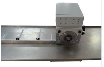
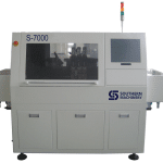
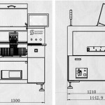
LED lights PCB Separator in surface mount technology

ledlight

Product Information:


1.LED light PCB separator using the latest V-cut lightweight design, complete the micro shear stress stroke cutting board,apply to cutting PCB circuit board with V groove.


2.The product is placed to the adaptive platform,moving along the guide piece,the lower circular knife rotating initiatively,quality guarantee.


3.Shear stress to a minimum, suitable for strip aluminum plate, LED light bar cutting.


4. Tools made of high-speed steel precision grinding, reusable abrasive use.

How much you know about Wave Solder?

Wave Solder:

Surface wave are covered by a layer of scale, it is in almost all along the length direction of the solder wave, keep the static, in the process of wave soldering, PCB exposure to the forefront of tin wave surface, oxide skin breakdown, in front of the PCB solder wave without being Jun folds forward, indicating that the entire scale and the PCB at the same speed mobile crest welder

Solder joint shape:

When the PCB into the wave front end (A), base plate and pin heated, and before his leave wave surface (B), the whole PCB in the solder, namely by solder bridging, but leave the wave at the moment, A small amount of solder due to the effect of wetting force, adhesion on the bonding pad, and due to the reason of surface tension, there will be A contract for the center with lead to minimum state, at this time between the solder and solder wetting ability than cohesion between two solder in solder. Therefore will form a full, round solder joints, leave the wave at the back of the excess solder, due to the gravity and back

Tin pot.

Prevent bridging:

  1. Use the solderability good components/PCB
  2. Improve the activity of welding Ji
  3. Improve the PCB preheating temperature, increase the solder wetting performance
  4. Increase the temperature of the solder
  5. Remove the harmful impurity, reduce the cohesion of solder, to facilitate the solder separated between the two solder joints.


The crest welder common preheating method:


  1. Air convection heating
  2. The infrared heater heating
  3. The method of combining the hot air and radiation heating


Wave soldering process curve resolution:

  1. The wetting time

Refers to the solder joint and the starting time of the solder wetting after contact

  1. The residence time

On a PCB solder joints from the wave surface contact to leave wave time below

Stay/welding time calculation is: stay time = wave width/speed/welding

  1. The preheating temperature

Preheating temperature is refers to the PCB and the temperature reached before the wave surface contact (see right-hand chart)

  1. Welding temperature

Welding temperature is very important for welding parameters, usually higher than the melting point of solder 50 ~ 60 ° C (183 ° C) ° C for the most part refers to the temperature of the soldering furnace operation, PCB solder joints welded by the temperature is lower than the results of the furnace temperature, this is because the PCB endothermic


SMA type             components        preheating temperature

Single panel component        hole device with conventional  90 ~ 100

Double panel component         hole device                   100 ~ 110

Double panel component         mixed                         100 ~ 110

A multilayer                through-hole device              115 ~ 125

A multilayer                 mixed                           115 ~ 125


Art and welder peak wave number to adjust:

  1. The wave peak height

Wave peak height refers to wave soldering PCB solder height. Its numerical control in PCB thickness usually 1/2 ~ 2/3 are exaggerated, solder melt flow will cause, to form a “bridge” on the surface of the PCB

  1. The transmission Angle

When peak wave welding machine is installed in the device level, should also be necessary to adjust the sexual transmission Angle of dip Angle, by adjusting to the abandoned domestic PCB, but the peak wave Angle of the welding, time, when is suitable for domestic will help more PCB welding fee liquid stripping sex fast, to return to the tin pot

  1. The cyclone knife

Tens of thousands of boom knife, sma peak wave put down, just left after welding in sma cavity “a long narrow long with open cavity of narrow,” illustrates the blow out hot function form, especially such as knife, therefore calls “sword” boom.

  1. The influence of solder on the purity

Wave peak during the welding process, welding source solder impurity) Shanghai plate [on PCB, analyse leaching copper will lead excessive copper content in welding defects

  1. Flux
  2. The parameters of industrial cooperation > >

Wave peak welding parameter > > industrial tape speed, and time of hot welding the reserved time and mutual cooperation, adjustment Angle of demand.


Wave soldering defect analysis:

  1. The POOR WETTING POOR WETTING:

This situation is unacceptable defects, only partially wetting on the solder joints. Analyze the reasons and improving ways are as follows:

1-1. External contaminants such as oil, grease, wax, etc., and such pollutants are usually available solvent cleaning, this kind of pollution is sometimes in the printing on the flux.

1-2. SILICON and lubricating OIL are normally used for stripping, usually in the base plate and parts found on his foot, and SILICON OIL is not easy to clean, so use it to be very careful especially when it does antioxidant OIL problems often happen, because it will evaporate to touch on the substrate and cause poor wetting.

Often 1-3.

Storage condition bad or substrate oxidation process on the problem, and the flux can’t remove will cause poor wetting, secondary tin or can solve this problem.

1-4. With flux method is not correct, cause the reason for foaming pressure instability or inadequate, causing unstable foam height or uneven and make the substrate part does not have to touch to the flux.

1-5. Insufficient solder time or tin temperature can lead to poor WETTING, because the temperature of the molten tin need enough time and WETTING, usually soldering temperature should be higher than the melting point temperature 50 ℃ to 80 ℃, WETTING the total time about 3 seconds. Adjust the solder paste viscosity.


  1. Partial wetting bad:

This situation is similar to poor wetting, different is bad local wetting will show no copper foil surface, only a thin layer of tin can’t form full of solder joints.

  1. Cold welding or solder joints is not bright,

Solder appears to be broken, uneven, most of the reason is parts solder was cooled in the formation of solder joints caused by vibration, pay attention to the tin stove whether there are abnormal vibration.

  1. The solder joint failure:

This situation is usually a solder, base plate, guide hole, and the expansion coefficient between parts feet, not cooperate, should be in the base material, improve the parts material and the design.

  1. Solder tin content is too big:

Usually in the evaluation of a solder joint, the hope can big, round and fat of solder joints, but in fact too much solder joints to electrical conductivity and the tensile strength is not necessarily help.

5 to 1. The tin stove transmission Angle is not correct will cause the solder joint is too big, by the tilt Angle

1 to 7 degrees in accordance with the substrate design approach? # 123; The whole, the general point of about 3.5 degree Angle, Angle, the greater the wetting Angle of the thinner the smaller wetting the more thick.

5 – (2) improve the tin bath temperature, longer soldering time, make the excess tin back into the tin bath again.

5 – (3) improve the preheat temperature, can reduce substrate wetting heat, have added to help welding effect.

5-4. Change the proportion of flux, slightly lower flux density, usually share the higher solder more thick also more easy to short circuit, the lower the proportion of tin solder the thinner but more easily cause bridge, icicles.

  1. Icicles (icicles) :

This problem usually occurs on the welding process of DIP or WIVE, at the top of the foot parts or had found ice point of tin solder joints.

6-1. The base plate weldability poor, this problem is often accompanied by poor wetting, this problem should explore by substrate weldability, try by flux ratio to improve the ascension.

6-2. Gold on a substrate (PAD) area is too big, can be used

Green (welding) proof paint line dividing gold way to improve that in principle with green (welding) proof paint line in daikin pavement separated into 5 mm by 10 mm block.

6 – (3) lack of tin bath temperature wetting time is too short, can be used to improve extension soldering tin bath temperature time, make the excess tin back into the tin bath to improve again.

6-4. After a wave of cool wind flow Angle is wrong, is blowing in the direction of the tin bath, will cause the solder point rapidly, excess solder cannot be affected by gravity and cohesion back to the tin bath.

6-5. Generated when the hand soldering tin peak, usually for the solder iron temperature is too low, inadequate to soldering temperature to solder joint formed by the cohesion bounce back immediately, switch to a larger wattage soldering iron, lengthen the iron in the preheating of the object being welded.

  1. The welding on the green paint with remnants of tin:

7-1. The base plate production residues have some with flux can’t compatible materials, overheating in the 餪 turn produce sticky stick after soldering tin wire, usable acetone (* chemical solvent has been disable the Montreal convention), and chlorinated solvents such as alkene to clean, if still can’t improve after cleaning, has the possibility of CURING substrate layer material is not correct, this accident should be timely feedback substrate suppliers.

7-2. Incorrect substrate CURING can cause this phenomenon, two hours before plug-in first bake 120 ℃, the project accident should be timely feedback substrate suppliers.

7-3. Tin tin slag is PUMP into the slot and then spray out the base plate surface with tin slag, caused this problem is relatively simple maintenance good tin furnace, tin tin bath right level (normal conditions when tin tin slot jet still not face away from the edge of tin bath 10 mm height)

  1. White residue:

After welding or solvent cleaning found a white residue on the base board, usually the remains of the rosin, this kind of matter will not affect the surface resistance is qualitative, but customers don’t accept it.

8-1. The problem of flux is usually the main reason, sometimes to switch to another flux can be improved, rosin type flux often produce work days, when the cleaning at this time the best way is to seek the assistance of flux suppliers, products is that they supply them more professional.

8 – (2) substrate residual impurities in the process of production, also can produce white spot under long-term storage, available flux or solvent wash.

8-3. Incorrect CURING also can cause the day, is usually a batch separately, should be timely feedback base board and the supplier use flux or solvent wash.

8-4. The factory using the flux and the base board of oxidation layer is not compatible, had occurred in the new substrate suppliers, or change the flux label, should ask the supplier to assist.

8-5. In case of substrate process used in the solvent to change the base material, especially in the process of nickel plating solution often cause this problem, suggestion storage time as short as possible.

8-6. Flux used for aging, exposed to the air absorbs moisture degradation, suggest update flux (usually foam type flux should be updated every week, immersion flux is updated every two weeks, spray monthly update).

8 to 7. The use of rosin flux, after soldering furnace hou parking time is nine to cleaning, cause the day shift, as far as possible to shorten the time of soldering and cleaning can be improved.

8 and 8. Solvent cleaning the substrate moisture content is too high, reduces the cleaning ability and produce day. Should update the solvent.

  1. Dark residue and etching trace:

Usually black residue had occurred in the bottom of the solder joint or at the top, this problem is usually incorrect use of flux or cleaning.

9-1. Rosin flux welding did not immediately after cleaning, dark brown left, to wash in advance as much as possible.

9-2. Acid flux on the solder joints caused by black color, corrosion and not cleaning, this phenomenon in the welding often found that switching to the flux of the weaker and cleaning as soon as possible.

9-3. Organic flux at high temperature burning, resulting in the class, to confirm the tin bath temperature, switch to more resistant to high temperature flux.

  1. Green residues:

Green usually is caused by corrosion, especially the electronic products but is not entirely true, because it is difficult to distinguish what is green rust or other chemical products, but generally found that green stuff should be warning, must immediately find out the reason, especially the green material will be more and more big, should pay attention to very much, usually available to improve the cleaning.

10 to 1. The corrosion problem

Usually occurs on the bare copper or copper alloys, the use of rosin flux, the corrosion substance containing copper ions so green, when found the green corrosion and can be proved after the use of rosin flux is not properly cleaned.

10-2. COPPER ABIETATES is COPPER oxide and ABIETIC ACID compounds (rosin main component), the material is green, but never is corrosive and high insulation, do not affect quality but the customer will not agree to clean.

10-3. PRESULFATE residue or similar residue substrate production, produce green residue after soldering, the base board manufactory should be asked substrate cleaning degree and then do test, to ensure the quality of the base board cleanliness.

  1. White corrosion:

8 talking about white residue is refers to the substrate white residue, and the project talking parts foot and white on metal corrosion, especially lead composition more easily into such residues on the metal, mainly because of chloride ion is easy to form lead chloride with lead, lead again with carbon dioxide to form carbonic acid corrosion (white). When the use of rosin flux, for rosin will does not dissolve in water containing chlorine surfactant wrapped from corrosion, but if use undeserved solvent, clean rosin can not only remove chlorine ion, thus has accelerated corrosion.

  1. The pinhole and the porosity:

Pinhole and the porosity of the difference, pinhole is to find a small hole in the solder joints, porosity is larger hole on solder joint can be seen inside, it is empty normally in the pinhole internal, internal air porosity is completely out and cause the size of the hole, the forming reason is solder in the gas has not been completely ruled out that has solidified, and form the problem.

12-1. Organic pollutants: base board and parts

Foot caused pinhole or porosity, gas may be produced its pollution source may come from planting a machine or storage condition, the problem is simple as long as the solvent wash, but such as contaminant SILICONOIL because its not easy to be solvent cleaning, therefore, should be considered in the process of other substitutes.

12-2. Substrate moisture: such as using the base material of cheaper, or use a rough way of drilling, the penetration hole easy absorption of moisture, soldering process caused by high heat evaporates, the solution is two hours at 120 ℃ baking in the oven.

12-3. The plating brightener in the solution: use a large amount of brightener, electroplating brightener with gold deposit at the same time, the high temperature caused by the volatile, especially when the gilded, switch to plating solution containing less brightener, of course it will feedback to suppliers.

  1. TRAPPED OIL:

Oxidation prevent oil Wells into Canon of tin bath flow and pollution substrate, this problem should be tin bath soldering fluid level is too low, additional soldering tin groove can be improved.

  1. Solder gloomy:

This phenomenon can be divided into two (1) for a period of time after soldering, solder joints (about half cargo to one year) turn dark color. (2) the manufactured product solder joints is grey.

14-1. The soldering the impurity: every three months must regularly test the metal ingredients inside the solder.

14-2. Flux on the surface of the heat will also have some degree of grey color, such as RA and the flux of organic acids on the spot for too long can cause slight corrosion and a grey colour, immediately after welding cleaning can be improved. Some inorganic acids can cause any ZINC flux OXYCHLORIDE available 1% hydrochloric acid cleaning and washing.

14-3. In solder alloy, tin residency content (such as 40/60 solder) solder joints in gray.

  1. Solder surface roughness:

Solder surface sand with prominent surface and the solder joint shape does not change as a whole.

15 to 1. The crystallization of metal impurity: every three months must regularly test the metal ingredients inside the solder.

Was 15-2. Tin slag, tin slag PUMP Wells into the Canon of tin bath jets for tin contains tin slag and make the solder surface of sand form, shall be the tin bath soldering fluid level is too low, tin groove add solder and should clean up the tin bath and the PUMP can be improved.

15-3. The foreign substances, such as flash, insulation materials, such as hidden in parts, also can produce a rough surface.

  1. Yellow spot:

Due to soldering temperature is too high, see if tin and temperature thermostat failure immediately.

  1. A short circuit:

Too much solder joints caused by two solder joints.

17-1. The solder didn’t have enough time, substrate preheating insufficient adjustment tin stove.

17-2. Flux bad: improper flux density, degradation, etc.

17-3. The substrate with tin wave direction and harmful, solder direction changes.

17-4. Bad circuit design: lines or contact between too close () should be more than 0.6 mm spacing; Such as array type solder joints or IC, should consider to steal soldering pad, or use white paint to separate words, at this time of white paint thickness for more than 2 times the thickness of welding pad (gold).

17-5. The contaminated tin or excessive accumulation of oxide by PUMP wear caused by short circuit should clean up the tin stove or further update all soldering tin groove.

 

USA IPC APEX EXPO 2016 exhibition


Welcome to visit our booth No. :#2930 in USA IPC APEX EXPO (Mar. 15th-Mar17, 2016)

ETA and Southern will attend the USA IPC APEX EXPO 2016 exhibition to share the industry’s top feast.You are warmly welcome to visit our booth No. :#2930 in USA IPC APEX EXPO (Mar. 15th-Mar17, 2016)

As the industry’s leading manufacturers, Wewould show our latest T-series lead-free reflow oven and at the same time, we will Strongly recommended Strongly recommended our Odd Form machines

in USA IPC APEX EXPO 2016 exhibition.This is unique machine in China now. It refreshes the traditional perception of reflow oven.

We are the professional manufacturer of reflow oven and offer full SMT solutions for customers. We have more than 20 years experience and technology in SMT filed. The most professional term and the best service are waiting for you. Our goal is to provide the reliable full SMT solutions to all the customers around the world.

ETA is our good global partner. We would provide the high-value technical support to our customers together.

You are warmly welcome to visit our booth No. :#2930.


3JL2@CTO66X1$AU_`YF$]JJ EH[MFM@97)KM071$D6AW[NL


Universal Insert machine In-line Automation Solution


Technical innovation Purpose

Reduces the labor intensity

To reduce the loss of equipment efficiency cause by operator sabotage

Save the operator, one person can operate multiple machines

In-line SMT production line

More operating security

Full Automatic production mode

Dispenser for high precision products

Fully automatic dispensing system bench top automatic visual glue dispenser  Automatic visual glue dispenser    is used to Chevrons,  fridge magnets, key chains,  power supply, cell phone,energy saving light, LED, DVD, DC, Switch, Connector, relay and other industries needing fluid glue solder.

Feature of  Glue dispensing equipment

1 Improve the production efficiency,reduce artifical loss.

2 Equipped with high performance CCD vision positioning system,visual dispensing route,improve accuracy.

3 Use industrial computer to control  operating system,

4 According to the different artifacts, choose suitable LED light source for lighting.

5 Adopt servo motor, ball screw drive.

6 It can arbitrary match with needle valve, diaphragm valve,screw valve, pnematic injection valve, piezoelectric injection valve.


Congratulation SOUTHERN MACHINERY has beed admitted as Foreign Member of ELCINA community

http://www.elcina.com

Electronic Industries Association of India identifies and bringstogetherlikeminded companies to represent the voice of Indian electronics and IT hardware industry and promote manufacturing.Electronic Industries Association of India promotes hardware manufacturing through active representation in the Government as well as scientific/technical institutions and industry/trade organisations in India and abroad.Electronic Industries Association of India represents to the government, problems faced by its members, individually or as a group, to find solutions and provide relief from unreasonable acts of administrative and policy making departments.

Electronic Industries Association of India provides a bouquet of professional and value-added services to its members. These services are tailored to serve the best interest of its Members and the Electronics/IT community to empower it to face competition and prosper. These services are constantly upgraded to suit the changing demands of the environment and needs of the industry.

Electronic Industries Association of India’s E-commerce facilities and its dynamic website together attract about 3500 visitors per day and provide a platform for members.

Electronic Industries Association of India is a repository of information and research, readily available for its members and helps them in taking critical decisions based on relevant facts.

Services currently provided by Electronic Industries Association of India to its members can be found by clicking here.

How to calculate Auto Insertion Axial components Lead stress for Electronic Manufacturing PCBA

Our engineering group performed calculations of the stress induced on axial components during the forming and insertion process. Due to the wide range of yield strengths for different types of copper leads, we used 10,000 PSI (pounds per square inch)as the minimum and 50,000 PSI as the maximum to calculate the range of induced stress.

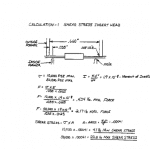
Lead forming at the insertion head shows the highest induced stress, which ranges from 4.1 pounds minimum, to a maximum of 20.5 pounds. (see calculation 1, below). Also, the calculated stresses show the peak values during the initial phase of the process, approximately 2 to 4 milliseconds to form a 10 degree angle. Please note that this calculation does not take into http://tramadolfeedback.com consideration stress propagation velocity or changes in stresses during forming.

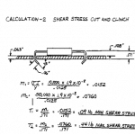
Lead forming at the Cut and Clinch shows significantly lower stresses than the lead forming process in the insertion head. At the Cut and Clinch, induced stress ranges from .09 pounds minimum to a maximum of .44 pounds (see calculation 2, below). Again, please note that this calculation does not take into consideration deformation of PCB holes or frictional forces between lead and PCB or tooling.

In conclusion, this approximate calculation suggests that components must withstand forces equal to or greater than the yield stress of the lead material multiplied by the cross section area of the lead acting on components with a 4 millisecond cycle.

Grease / Oil for Electronic Manufacturing SMT machine

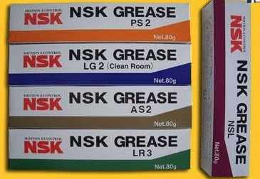
We provide a variety of Grease /  Oil for Electronic Manufacturing SMT machine

NSK Series lubricants


NSK NSL oil is linear guide for oil.

NSK PS2 is a high- precision high-speed grease lubricants . Use advanced synthetic base oils , urea thickener and special additives , has excellent corrosion resistance and abrasion resistance and long service life , suitable for high speed , the temperature, the use of small high-speed machinery , suitable temperature is 190 degrees.

nsknks66331428570405

NSK LG2 grease lubricants are dedicated clean room , pollution , specifically for semiconductors,

20141104102434_9888

LCD manufacturing equipment and food machinery.

NSK AS2 oil is heavy , waterproof anti- corrosion grease with precision .

PastedGraphic-9

NSK LR3 grease lubricant is high temperature and high precision .

 PastedGraphic-10

NSK GREASE NSL

Lubricants for linear guide for oil, mainly used in our industry Yamaha SMT machines, special screw on the Y -axis X -axis , because the parts at high speed while the ball requires a lot of lubrication, because this oil has excellent wear characteristics , can effectively inhibit the high-speed friction problem when used .

Packing : 80G / branch ;AI spare parts、Universal Parts,UIC,TDK.VCD Sequencer.SMT,THT,PCB,PCBA,AI,wave soldering,reflow oven,nozzle,feeder,wave soldering,PCB Assembly, LED, LED lamp, LED display

Manufacturer : NSK CO, LTD Seiko Corporation . .

Usage: can be used with Japanese NSK HGP oil gun to use , but also with THK MG70 grease guns , shaped nipple tubing complete SMT equipment maintenance refueling dedicated .


NSK GREASE PS2

● Features

The main component of the base oil used in synthetic and mineral oil , having excellent lubricating properties of the high-speed driving at a low temperature with a light load in terms of grease .

● Use it NSK miniature ball screw linear guide and standards adopted lubricant. Although it is very excellent driving characteristics of low-temperature lubricant , at room temperature, but also has good turning characteristics , it is very suitable for precision load small precision machine.

In our industry, mainly for the private placement on a Yamaha machine, low speed bearings and sliders, shortcomings , the temperature is not high , wear is not very good .

Packing : 80G / branch ;

Manufacturer : NSK CO, LTD Seiko Corporation . .

Usage: can be used with Japanese NSK HGP oil gun to use , but also with THK MG70 grease guns , shaped nipple tubing complete SMT equipment maintenance refuel special .


GREEN NS7

NSK GREASE NS7 lubricants, adapt the temperature from -40 ℃ to 140 ℃ to some extent can be used for a wide range of temperatures. The product is a low base oil viscosity , good lubricating properties.

Features:

A high durability and excellent performance, long-life grease

2 low-temperature performance and excellent mechanical properties at high speed during operation , some oil leakage.

3 .. low wear, at room temperature , in order to reduce bearing friction torque.


5 grease excellent performance can be maintained for a long period of time.

6 to have excellent water resistance .

(7) The effect of the product can reduce the brine excellent rust device

Which products for FUJI SMT , NXT and CP842 dedicated

Packing : 80G / branch ;

Manufacturer : NSK CO, LTD Seiko Corporation . .

Usage: can be used with Japanese NSK HGP oil gun to use , but also with THK MG70 grease guns , shaped nipple tubing complete SMT equipment maintenance refueling dedicated .

NSK LR3

● Features

     Refined mineral oil in the base oil, grease, and a lithium-based thickener additives of special abrasion resistance, excellent extreme pressure resistance of the pan with a large load with grease. It has the load resistance and excellent oxidation stability , maintain good lubrication performance for a long time , and with high lubrication life. Excellent water absorption , even in the state contains a lot of water under , it will not be washed away by the water softener .

● Use

     It is common grease NSK linear guide and ball screw standards adopted . Oil dynamic viscosity, excellent load resistance , oxidation stability is also very good , it can be widely used for various purposes , is a common type of grease used .

In our industry, mainly for Yamaha SMT machines, special bearing on l , paragraph grease lubricants are high temperature and high precision , large-scale metal processing machine tool spindle bearings specifically for high-speed , high-temperature , high load for the girth greater than 62MM high-speed bearings , which can effectively improve the machining accuracy and extend bearing life.

Packing : 80G / branch ;

Manufacturer : NSK CO, LTD Seiko Corporation . .

Usage: can be used with Japanese NSK HGP oil gun to use , but also with THK MG70 grease guns , shaped nipple tubing complete SMT equipment maintenance refueling dedicated .


NSK GREASE LG2 / NSK GREASE LG2 (Clean Room)

Features: The grease used as a clean room of the Department of straight rails and ball screws and other special grease , developed by NSK alone products, with the original clean room compared to the commonly used fluorinated grease , it has a high lubricity, lubricating long life, stable fat torque characteristics ( slip resistance ) , etc. , also have high rust resistance and dust characteristics , to achieve the same grease better than other low dust characteristics. Furthermore, not a special base oil used instead of mineral oil , the same method can be used ordinary lubricants.

Uses: For high cleanliness requirements of semiconductor , liquid crystal lubricant Linear Guides (LCD) manufacturing equipment , such as the use of a ball screw and rotating products. But the pressure of the grease dedicated clean environment , it can not be used in a vacuum environment .

 In our industry, mainly for Yamaha SMT , COB bonding machine.

Packing : 80G / branch ;

Manufacturer : NSK CO, LTD Seiko Corporation . .

Usage: can be used with Japanese NSK HGP oil gun to use , but also with THK MG70 grease guns , shaped nipple tubing complete SMT equipment maintenance refueling dedicated .


NSK GREASE AS2

One can withstand , with a gravity well.

Second, the continuing good , good adhesion, good adhesion .

Third, the product has a certain acidity , resistant to corrosion.

Fourth, a strong water resistance.

Disadvantages : The temperature is not good, poor wear resistance.

In our industry, mainly for Yamaha SMT machines , special placement head , because this part of the low-speed operation , while only need to play a minor slip can be lubricated . Packing : 80G / branch ;

Manufacturer : NSK CO, LTD Seiko Corporation . .

Usage: can be used with Japanese NSK HGP oil gun to use , but also with THK MG70 grease guns , shaped nipple tubing complete SMT equipment maintenance refueling dedicated .

AI spare parts、Universal Parts,UIC,TDK.VCD Sequencer.SMT,THT,PCB,PCBA,AI,wave soldering,reflow oven,nozzle,feeder,wave soldering,PCB Assembly, LED, LED lamp, LED display

ETA and Southern Machinery will attend the USA IPC APEX EXPO 2016 exhibition

ETA and Southern Machinery will attend the USA IPC APEX EXPO 2016 exhibition to share the industry’s top feast.


You are warmly welcome to visit our booth No. :#2930 in USA IPC APEX EXPO (Mar. 15th-Mar17, 2016)

As the industry’s leading manufacturers, ETA would show our latest T-series lead-free reflow oven together with Southern Machinery in USA IPC APEX EXPO 2016 exhibition.This is unique machine in China now. It refreshes the traditional perception of reflow oven. T-series lead-free reflow oven could ensure the lead-free process optimization under the condition of the smallest footprint and the lowest power consumption. It could meet all customer’s demand. Meanwhile, Many new special equipment will also be displayed at this show.

ETA is the professional manufacturer of reflow oven and offer full SMT solutions for customers. We have more than 20 years experience and technology in SMT filed. The most professional term and the best service are waiting for you. Our goal is to provide the reliable full SMT solutions to all the customers around the world. Southern Machinery is our good global partner. We would provide the high-value technical support to our customers together.

www.smt11.com,

www.smthelp.net

You are warmly welcome to visit our booth No. :#2930.

AI spare parts、Universal Parts,UIC,TDK.VCD Sequencer.SMT,THT,PCB,PCBA,AI,wave soldering,reflow oven,nozzle,feeder,wave soldering,PCB Assembly, LED, LED lamp, LED display

AI spare parts、Universal Parts,UIC,TDK.VCD Sequencer.SMT,THT,PCB,PCBA,AI,wave soldering,reflow oven,nozzle,feeder,wave soldering,PCB Assembly, LED, LED lamp, LED display
Southern Machinery:Provide SMT whole line solution.

Lead-free & Good quality & Cheap Solder Paste

Product Description

This solder paste special for SMT production process. It is made from the special solder paste and sphere tin power with little oxide content. It has the excellent performance in continuous printing. It has very little residue after reflow and very good insulation impedance. With various alloy composition, different diameter of tin powder, and metal content to meet the customer need in products and process requirement.

Product Feature and Selling points                                                                                                           

  1. 1.    Good http://shopantibioticsonline.com rollability in printing, excellent performance in printing even for 0.3mm part spacing in steel plate.
  2. 2.    Little changes for the viscosity for continuous printing, longer life time for the stencil, and good printing performance even for continuous 8 hours printing.
  3. 3.    No slump electron migration several hours after printing.
  4. 4.    Excellent welding performance and proper wettability in different parts.
  5. 5.    Adaptable to different level of welding equipments, finish welding with no nitrogenization, good performance in welding even in wide range reform temperature.
  6. 6.    Very little residue, light in color, and good insulation impedance and no corrosion to PCB, no need clean.
  7. 7.    Good testing performance in ICT.
  8. 8.    Workable for paste in Hole process
  9. Solder paste3 Solder paste6 Solder paste2 Solder paste1 Solder paste IMG_2792

PCBA Quality Process Audit — SMT Pick and Place machine

1. Work Instructions
1.1 Is there a revision controlled Operator Work Instruction which contains loading information for the specific product being built? (Score 0 if any unsigned/undated handwritten instructions or any handwritten instructions more than 48 hrs old)
1.2 Are Work Instructions readily available to the operator and are they followed at Component Placement?
1.3 Are component part numbers and descriptions included on the Work Instructions?
1.4 Are component descriptions sufficiently detailed to check at first-article that the correct components are being used?
1.5 Is the machine head/slot number for component loading specified for each part number on Work Instructions?
1.6 Are the reference designators and the quantity per part number specified on Work Instructions?
1.7 Is the component feeder type/size specified on Work Instructions or otherwise for each component package type?
1.8 Is the machine Program Name specified on the Work Instruction or line set-up instructions?
2. Component Loading and Verification
2.1 Is there an automated bar coded component loading verification aid in order to reduce the probability of incorrect loading? Note*
2.2 Are the component loading verification aids hard linked to the placement program so that loading is verified against program data?
2.3 Can traceability of component lot codes be demonstrated for critical devices?
2.4 Is component loading/changes verified and cross checked by an individual other than the set-up operator at product changeover? Note*
2.5 Is a component loading/changes verification log signed by the set-up operator and countersigned by the cross checker before start up? Note*
2.6 Is the correct feeder loading base used to facilitate real to feeder loading?
2.7 Are first-built boards verified against documentation for missing/misplaced components and for correct component polarity?
2.8 Are first-articles conducted using AOI methods and complemented with description verification and value metering?
2.9 Are all Resistors & Capacitors measured for a value within the tolerance (one per part number) at first-article & at reel change?
2.10 Is a first-article log signed to verify acceptance before start up?
2.11 Is the orientation of Tantalum SMT capacitors, Diodes, etc in tape format, standardized and documented for polarity orientation?
2.12 Is the IC tray loading polarity standardized for each type of polarity indicator that can be used for each component?
2.13 Is loading polarity referenced both from the tray and the component so as to ensure retrayed components are correctly loaded?
3. Nozzles, Feeders, and Tooling
3.1 Is there a document which details the standardized nozzle diameter set-up selected for each type of placement equipment?
3.2 Are these standardized nozzle diameter set-up documents readily available for when nozzles need to be replaced or changed?
3.3 Is there a document which details the range of component XYZ body sizes that each selected nozzle type can successfully place?
3.4 Is there a documented requirement to conduct daily nozzle centering and is there evidence that this is done?
3.5 Is each feeder identified with its own unique serial number?
3.6 Is there a documented and effective Feeder Maintenance Program? Records (s/w or otherwise) must be by Feeder Serial Number.
3.7 Are database records maintained for each feeder serial number for the purpose of tracking its maintenance history and performance?
3.8 Is feeder maintenance history used to monitor feeder life so that problematic feeders can be removed from the process?
3.9 Can it be demonstrated that the number of feeder indexes is counted & monitored for each unique feeder using software or otherwise?
3.10 Is this information used to flag that feeder preventative maintenance is required after x number of indexes?
3.11 Is there a documented requirement to indicate that Blocks or Support Pins are needed for specific products?
3.12 Is the No, location, type and height of Support Blocks/Pins identified on a product by product basis? Score NA if in 3.11 there are not needed.
3.13 Are the Support Pin locations identified for each product using templates/tooling or some other effective solution? Comment as above.
4. Moisture Sensitive Devices
4.1 Are components stored before loading and after unloading in a manner which prevents damage?
4.2 Are the Moisture Sensitive Devices (MSDs) and their sensitivity level readily known to the operator?
4.3 Are MSDs time stamped at opening and their exposure time monitored against pre determined limits?
4.4 Is there a flag to indicate that the exposure time has been exceed for any given device in a dry box?
4.5 Is there a flag to indicate the MSD exposure has expired for any MSD device currently loaded in the placement machines?
4.6 Have MSD procedures been updated to reflect the JEDEC standard for MSD control? (J-STD-033A MSD released in July 2002)
4.7 Is there evidence of correct implementation of J-STD-0033A for all MSD devices?
4.8 Are there MSD procedures in place to ensure MSD shelf life is reduced based on measured Relative Humidity conditions?
4.9 Is there a method in place to address the time spent in dry storage and its effect on remaining life based on MS Level and RH Level?
4.10 Is it clearly understood that MSD ‘shelf life’ continues to degrade during dry cabinet storage of some MSD devices?
4.11 If MSDs are on both sides of a PCBA, is there an effective method to account for time between 1st and 2nd reflow?
4.12 Can MSD control be demonstrated for MSD devices that need internal/external pre-programming?
4.13 Can MSD control be demonstrated for rejected devices and devices used for rework?
4.14 Have MSD recovery methods been defined and adequate for all component types?
4.15 Does the control of Moisture Sensitive Components include those components on reels?
4.16 Is the baking or hot room storage time and temperature documented and controlled for component recovery?
4.17 Has this time and temp been determined based on the component supplier’s guidelines / J-STD-0033A?
4.18 Is there evidence to demonstrate that the control process for MSDs is in use and is effective?
5. Machine Capability
5.1 Are Component Placement Programs generated from CAD XY coordinate data?
5.2 Is there a standardized nomenclature for Shape Code definition?
5.3 Can this nomenclature be used to determine the most appropriate shape code to allocate to a given part of given dimensions?
5.4 Are localized fiducials used for fine pitch devices when localized component fiducials exist on the board?
5.5 Has manual component moving been eliminated given correct CAD, nozzle set-up, Shape Code allocation, local fiducials, Cam speed, etc?
5.6 Does the Fine Pitch placement machine have the capability to check lead Coplanarity in xyz?
5.7 Does the Fine Pitch placement machine use its coplanarity capability on all leads of 20 mil pitch or less, and all programmed parts?
5.8 Does the Fine Pitch placement machine have the capability to check ball arrays? If no such device, score NA.
5.9 Does the Fine Pitch placement machine use its ball array verification capability for all BGA devices? If no such device, score NA.
5.10 Is the machine Program Name revision controlled to show traceability of program changes?
5.11 Is the machine Program Name traceable to the PWB and PCBA part number?
6. PCBA
6.1 Are outputted boards at least sample inspected pre reflow for placement positional accuracy for machine control purposes?
6.2 Is the frequency for this verification defined and documented, and is there evidence to suggest it is followed?
6.3 Is there a visual aid available which identifies the populated locations with polarity, and also the no-pop locations?
6.4 Is there a placement standard pre reflow to validate placement accuracy for the shape code, nozzle allocation, etc. parameters used?
6.5 Is there evidence to demonstrate that action is taken to adjust the machines performance for when this standard is exceeded?
7. Attrition Rates and Rejected Components
7.1 Is attrition rate monitoring conducted systematically to ensure feeder and/or nozzle problems are captured at least hourly?
7.2 Is there documented evidence to ensure attrition rates are checked and actioned at least hourly to ensure process control?
7.3 Is there a specification defined for acceptable attrition rates for the individual feeders?
7.4 Is there a specification defined for the maximum allowable number of nozzle skips per machine before it is shut down for repair?
7.5 Are these specifications determined based on a percentage combined with the number of placements for a given time period?
7.6 Is there evidence to demonstrate that attrition rate monitoring is conducted, effective, and used to make process control decisions?
7.7 Is there a documented process for the disposition or reuse of machine rejected components? Rs and Cs must not be reused even for rework.
7.8 Are rejected components reviewed and repaired to ensure conformance before reuse, even if only used for rework?
7.9 Are there repair blocks available or a lead conditioner in use for repairing ‘real’ Coplanarity rejects? Score 0 if parts not repaired.
7.10 Does the re-traying process always ensure that component polarity wrt the tray and the component loading polarity is preserved?
7.11 Is there a documented Process Deviation procedure to manage machine skips for hand placement if hand placement is allowed?
8. Process Capability
8.1 Has a Process Capability Analyses (PCA) been conducted and the Cpk acceptable for the suite of shape codes in use?
8.2 Were shape code allocations, component nozzle allocations, cam speeds, etc. recorded for this PCA?
8.3 Are the recorded shape code allocations, component nozzle allocations, and cam speeds, the same as those used today?