How to invest LCD TV Final Assembly factory

Volume Requirements

  • Total estimated time to complete weekly- production volumes with proposed equipment set = 160 hours/per week (+/- 10%)

Notes:

  • Available time is 80 hours (16hours x 5days)!
  • Factory efficiency not optimum due to:
  • Weekly Scheduling
  • Bottle Neck is SM Lines (Top/Bottom)
  • Occupation of Lines, High Volume PC’s
  • For schedule improvements we propose:
  • To add and reconfigure SMT lines, create dedicated HV PC & PC Monitor SM lines
  • Increase inventory, make longer runs, increase weekly batches, warming up Factory

IM Lines

DIP, PCB Assembly,Chip Mounter, Pick and Place, IC Mounter, High Speed Mounter, Wave soldering,LED lighting, LED Lamp, LED Display, LED tube,UPS, Power Converter, Power Adepter, Mobile Charger, PCB board handling system, Loader, Unloader, Conveyor,Shuttle, Chip Mounter, Pick and Place, IC Mounter, High Speed Mounter Induction Cooker, AC, Electric Cooker, Fan, TV, Settle Box

  • Number of Lines : 3
  • Machine Set: Radial S-3000 x 3, Axial S-4000 x 3
  • Cycle time: Average 15 seconds
  • Intrinsic Availability: 90%
  • Mean Time To Repair: 120 seconds

SM Lines

  • Number of Lines : 4
  • Machine Set: High Speed Chip mounter x 2, IC mounter x 1
  • Cycle time: between 12.60 & 25.29 seconds
  • Intrinsic Availability: 90%
  • Mean Time To Repair: 120 seconds

DIP, PCB Assembly,Chip Mounter, Pick and Place, IC Mounter, High Speed Mounter, Wave soldering,LED lighting, LED Lamp, LED Display, LED tube,UPS, Power Converter, Power Adepter, Mobile Charger, PCB board handling system, Loader, Unloader, Conveyor,Shuttle, Chip Mounter, Pick and Place, IC Mounter, High Speed Mounter Induction Cooker, AC, Electric Cooker, Fan, TV, Settle Box

MI Lines

  • Number of Lines : 4
  • Machine Set:
  • 10 x Assembly stations,each line
  • Delta 5 Wave Solder, each line
  • 4 x Test & Inspect stations, each line
  • Average Cycle Time: 25 seconds


DIP, PCB Assembly,Chip Mounter, Pick and Place, IC Mounter, High Speed Mounter, Wave soldering,LED lighting, LED Lamp, LED Display, LED tube,UPS, Power Converter, Power Adepter, Mobile Charger, PCB board handling system, Loader, Unloader, Conveyor,Shuttle, Chip Mounter, Pick and Place, IC Mounter, High Speed Mounter Induction Cooker, AC, Electric Cooker, Fan, TV, Settle Box


LCD TV FA Lines

  • Number of Lines : 2
  • Machine Set:
  • 16 x Assembly stations
  • 3 x L-Shape Soak System 30 min
  • Simulation Soak is 30 min with 30 stations x 3
  • Final QC/Test and Pack Out, 3 stations
  • Two identical Lines (19” to 42”) for optimum Efficiency & Flexibility
  • Average Cycle Time: 24 seconds/station

DIP, PCB Assembly,Chip Mounter, Pick and Place, IC Mounter, High Speed Mounter, Wave soldering,LED lighting, LED Lamp, LED Display, LED tube,UPS, Power Converter, Power Adepter, Mobile Charger, PCB board handling system, Loader, Unloader, Conveyor,Shuttle, Chip Mounter, Pick and Place, IC Mounter, High Speed Mounter Induction Cooker, AC, Electric Cooker, Fan, TV, Settle Box


PCB Assembly,SMT,PCB,AI,THT,LED DIP, PCB Assembly,Chip Mounter, Pick and Place, IC Mounter, High Speed Mounter, Wave soldering,LED lighting, LED Lamp, LED Display, LED tube,UPS, Power Converter, Power Adepter, Mobile Charger, PCB board handling system, Loader, Unloader, Conveyor,Shuttle, Chip Mounter, Pick and Place, IC Mounter, High Speed Mounter Induction Cooker, AC, Electric Cooker, Fan, TV, Settle Box 1 S-4000_副本 S4000-Specification-3 PastedGraphic-3


LED lighting, LED Lamp, LED Display, LED tube

How to invest future – Auto Insertion and SMT equipment ROI calculation

Fill in “Green Areas” on Summary Sheet Below & Production Need Sheet

Calculations in “Blue” or “White” and should not be changed

INPUTS
Financial Machine Price Depreciation Time (Years)

Electricity Cost ($/kWHr)

US$ 205,000

5

US$ 0.1200
Machine Data Configuration Pass Thru / Non Pass Thru

Spec Speed

Sm Triple Span (2.5/5.0/7.5) Pass Thru (Automatic BDH)

22,000

Labor Rates / Hour Machine Operator Maintenance
US$ 10.00 US$ 15.00
Factory Work Time

Hours / Day

Days / Week

Weeks / Year

20

6

50

Hand Labor

Hand Labor Rate

Insertion Rate / Hour

US$ 6.00

250

OUTPUTS
Production Data
Insertions Needed   4,900,000 Annual Component Insertion
Machine Work Time
Machine Time

613

Hours to MFG
Hours in Year

6000

Machine Utilization

10.22%

Machine Yearly Costs
Depreciation US$ 41,000 Straight Line Depreciation
Utilities US$ 155 Electricity for Machine & Air
Maintenance US$ 900 Parts & Labor for Machine
Operator US$ 6,132 Operator Time @ machine
Total Yearly Costs US$ 48,186 Sum of all costs
Hand Labor Equivalents
Labor Hours   19,600
Labor Costs US$ 117,600
MACHINE DRIVEN SAVINGS
Hand Placement Cost US$ 117,600 Per Year
Machine Placement Cost US$ 48,186 Per Year
Annual Savings US$ 69,414 Per Year


Price

Unit

Notes

Machine Cost

US$ 205,000

$

Machine Costs

Depreciation Time

5

Years

Straight Line Assumed

Yearly Deprciation Expense

US$ 41,000

Result

Work Days per Week

6

Days

Hours Per Day

20

Hours

Weeks per year

50

Weeks

Hours per Year Available

6,000

Hrs/Year

Work Hours per Year

PM  Hours per 100 Hrs

12

Hours

Maintenance

Machine Working Hours

522

Hours

Total Production Hours

Maintenance Intervals

5

Periods

Maintenance Times

Maintenance Time

60

Hours

Maintenance Times

Maintenance Labor Cost

US$ 900

Costs

Labor Hours x Rate

Production Hours Needed

522

Hours

Machine Production Time

Intrinsic Availability

94.00%

Uptime

Downtime (Increased based on Age)

Lost Hours

31

Hours/Yr

Downtime

Machine Hours To Produce

553

Hours

Production Hours

Guide Jaw / Clinch Costs

US$3,000

Cost

Per Unit

Tooling Replacement

6,000,000

Cycles

Cycles per replacement

Tooling Replacements / Yr

0

Replacements

Replacements Needed

Yearly Replacement Costs

US$0.00

Costs

Total Yearly Tooling Costs

Chain Clip Replacments

US$780

Cost

Cost Per Replacement

Tooling Replacement

15,000,000

Cycles

Cycles per replacement

Tooling Replacements / Yr

0

Replacements

Replacements in a Year

Yearly Replacement Costs

US$0.00

Costs

Total Yearly Chain Costs

How to improve Auto insertion machine spare parts lifetime ?

Continuity Tube Life Expectancy

Applies to tubes used in Generation 8 clinch units.

The expected life span of a Continuity Tube is dependent upon a number of factors including:

  • Lead Composition

A Continuity Tube that is subjected to steel leaded components will cause more stress between the cutter, the cutter Bushing, and the continuity Tube. Expect to experience a higher wear rate on a continuity tube that is subjected to stiffer lead material than a continuity tube that is subjected to softer leaded material.

  • Lead Diameter

A larger lead diameter will cause more stress between the cutter, the cutter bushing, and the continuity tube. Larger leads being cut will accelerate the wear of a Continuity Tube.

  • Tooling Maintenance

Worn Tooling (cutters and cutter bushings) will cause the scrap lead to ‘tear’ instead of cut with a sharp clean cut. This ‘tear’ in the lead will accelerate continuity tube on both the metal tube and the plastic surrounding the metal tube. The tooling should be changed at recommended intervals, sooner if tearing of leads is noticed.

  • Working Environment (dust, humidity, temperature, etc.)

The continuity tube should be kept as clean as possible. Dust buildup caused as a result of the cut/form process and clinching process will grind into the metal tube and the plastic surrounding the metal tube possibly causing accelerated wear of the continuity tube.

There are too many variables associated with the performance of a continuity tube to allow Universal to list it as ‘consumable tooling’ and publish an estimated life span. The greatest life span will be generated by keeping the continuity tube as clean as possible, keeping the lead length within the middle of acceptable lead length range, and changing the cutters and cutter bushings on a regular basis.

Continuity Tubes and False Insertion Errors

Proper continuity lead sense is dependent upon the relationship between:

  • the continuity tube
  • the cutter
  • the angle of the lead being cut
  • the lead length as the leads are cut.

It is important the lead is bent and touches the continuity tube before the cut takes place, making the position where the lead enters the cut and clinch assembly very important.

As the cutter moves across to the cut position, the lead begins to bend in the direction of the continuity tube.  However, once the lead is pinched between the cutter and the cutter bushing, the scrap portion of the lead will no longer be pushed toward the continuity tube.  At this point the scrap portion of the lead will actually be forced in the opposite direction of the continuity tube as the cutter shears through the lead.

The following scenario describes what happens if the lead length is set too short.  In other words, the lead entrance to the cutter bushing set so the lead is very close the cutter bushing shear point.

By setting the lead length too short, (the lead too close to the cut point of the cutter bushing), the scrap portion of the lead will not be bent far enough to reach the continuity tube as the cutter bends the lead, resulting in a false insertion error.  In other words, if the lead reaches the cut point before it has been bent far enough to touch the continuity tube, a false continuity error may occur.

On the other hand, having the lead length too long may cause accelerated wear and damage to the continuity tubes.  Forcing the lead into the continuity tube with too much force will cause denting of the continuity tube and wear of the plastic insulation, resulting in premature failure and false continuity errors over time. 

Cutter Stroke Speed and false Continuity Errors

The length of time necessary to drive the Cutter from the home position, to the extended ‘cut’ position, can affect continuity sensing.  If the cutter speed is set too slow, the cutter air pressure is insufficient, or a mechanical assembly used in the operation of the cutter stroke binds, the cutter will not reach the component lead in the ‘window’ of time necessary for continuity to be sensed.  This will result in a false continuity error.  Examples of cutter stroke speed problems:

  • Pneumatic flow control for the cutters not properly set
  • Poor air flow from the valve to the cutter
  • Binding in the mechanical linkage from the cutter piston to the cutter
  • Lack of sufficient lubrication in the mechanical linkage from the cutter piston to the cutter
  • Incorrectly set cutter backstroke (the starting position for the cutter)
  • A torn O-ring on the cutter piston which causes a bind in the cylinder
  • Lack of sufficient lubrication on the O-ring for the cutter piston

END

The Automobile Industry is demanding more, have you invested in your SMT Equipment?

Assess Your SMT Equipment Line-up

Is your SMT Equipment Line-up Prepared for Increased Automotive Demands in 2017?

Southern Machinery SMT Feeder

Are you keeping up with SMT demands from the Automotive Industry this year? The demand for automotive electronic products is in direct link with the needs for surface mount technologies. The needs of growing in-car technologies include: embedded infotainment, telematics, connected safety, and security. As car designs continue to become more intelligent and technologically integrated, suppliers must gabapentin online keep up with the ever increasing demands.

It is imperative that PCB manufacturers serving the Automobile Industry assess their current Equipment Line-up for complete preparation of these growing global trends and automobile advancements.  Is your operation ready for full-scale capabilities to serve the Automobile Industry Demands? Would you like to begin manufacturing to supply these needs? Click the link below to contact us for an evaluation of your current operations.

Southern Machinery S-600-OF

Southern Machinery S-600-OF                                         Southern Machine S-600-OF

What is First Article Inspection

First Article Inspection overview

Before the manufacturing course begins, business necessities require an in depth verification and comparability of product design vs. manufacturing outcomes, often called First Article Inspection (FAI). Frequently used within the aerospace, medical electronics and automotive industries, FAI studies have gotten an ordinary course of to make sure high quality and consistency of the ultimate product is in order. Although conducting FAI could be advanced, technological developments and person pleasant software programs have allowed customers to implement and execute this course of shortly and precisely.

What is First Article Inspection?

As an official authentication technique for production, FAI intention is to overview and authorize dimensional studies. FAI stories make the most of dimensional properties of a manufacturing like design specs, to make sure of consistency or uncover any deviations. This inspection ensures reliability and repeatability of the manufacturing course, in addition to making certain the producer’s capability to provide elements in accordance with specifications.


What is the aim of FAI?

The goal of a FAI report outlined below:

  1. The FAI report supplies a tenet for goal affirmation that every engineering design and specification is appropriately understood, accounted for, verified and documented.
  2. Ensure the manufacturing course of action is dependable, repeatable and constant
  3. Develops a transparent understanding and communication outlet between purchaser and provider.
  4. Verify the accuracy of drawings, making certain that each adjustments made to any part of the designs are accounted for.
  5. Validate all tooling used for production, guaranteeing the instruments’ capabilities to supply all required elements at defined and accepted speed.
  6. Ensure manufacturing course is succesful and might meets the entiretly of all manufacturing needs.

When is FAI report crucial?

FAI studies are crucial when any of the following occur:

  • A change in design which may probably have an effect on match, kind or operation
  • A change in manufacturing supply, course of action, inspection technique, location of producer, tooling or supplies
  • A change to a special media program that will likely have an effect on match, kind or performance
  • Production has not been executed for 2 years or more (or as specified by buyer)

FAI Benefits

Before proceeding with manufacturing elements, FAI studies will be helpful in figuring out whether or not a production course of action is able to deliver elements constantly within design parameters. Furthermore, FAI studies present construction between buyer and provider for understanding and verifying the final mission necessities. FAI additionally assists buyer and provider with communications and help to avoid future miscommunication. This course of action additionally ensures that you will be using the precise supplies and instruments, offering an efficient initiative for the anticipated outcomes for manufacturing.

Full FAI vs. Partial FAI

A full FAI requires that each field has been accounted for.  With a partial FAI report, any subject missed will affect the FAI sucess. In regards to any excellent fields, they might be crammed out at a later date or utilizing earlier knowledge, on condition that it applies to the precise traits of duplicate elements produced by the identical manufacturing course of action.

FAI Planning

Before the primary manufacturing beings to run elements, many components have to be accounted for with the intention to execute FAI planning, which generally embrace the following:

Records for the manufacturing course of action– manage actions to be executed all through FAI course of and accountable suppliers/organizations.

Ensure authorized  materials sources, laboratory and relevant manufacturing, planning, routing and buying are in accordance with the specifications.

Save

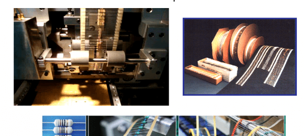
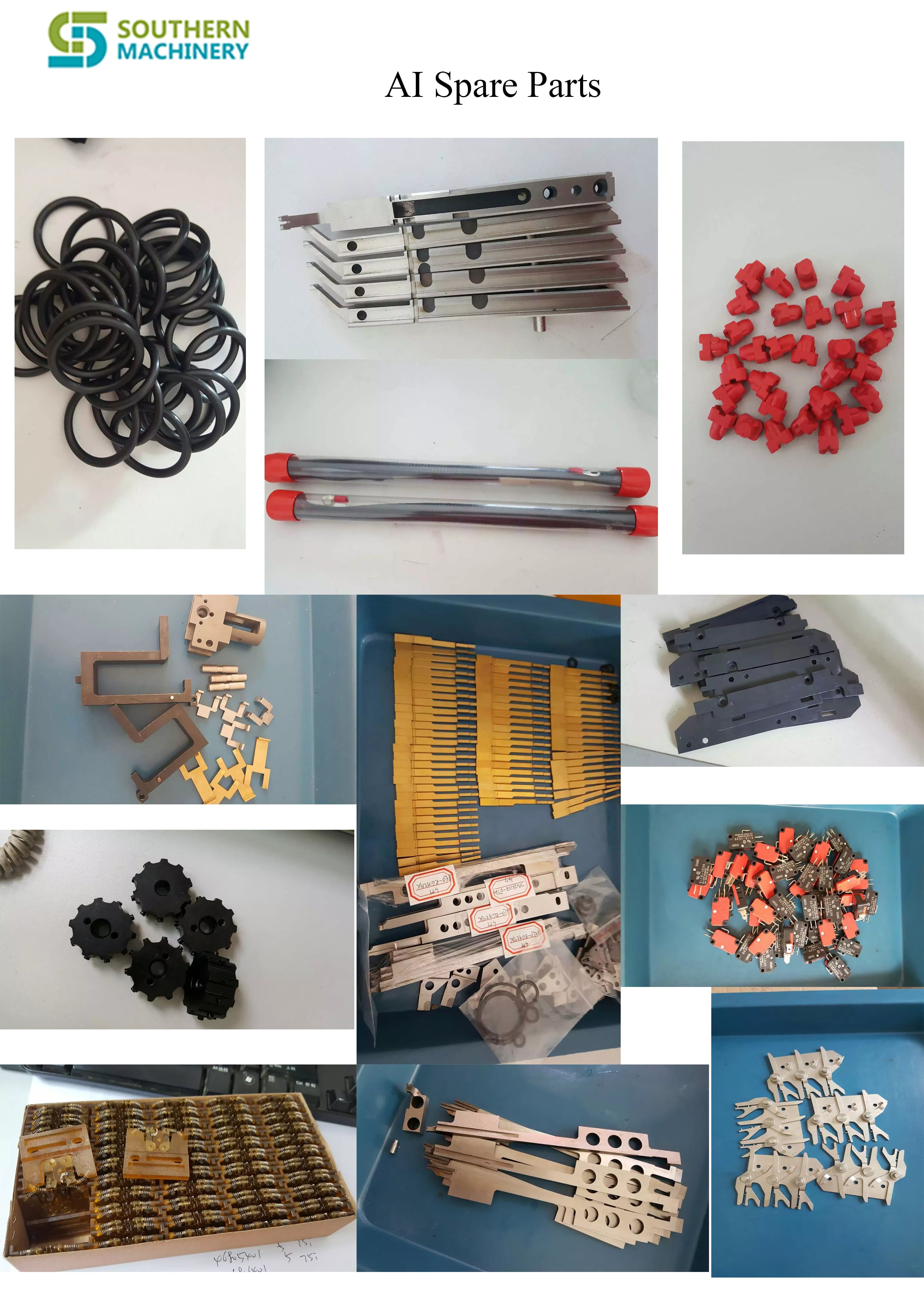
Carrier clip -AI parts

Carrier Clip is the very common wearing parts in Radial insertion machine.

We manufacture the high copy spare parts , promise the quality and keep low cost .

Very welcome to inquiry .
CLICK HERE TO SEND ME A EMAIL

Here is a brief summary about the products we provide:

1.SMT Equipments,include:

  • 1.One stop LED SMT whole line solution
  • 2.SMT peripheral equipments

2.AI Equipments,include:

  • 1.Axial insertion machine
  • 2.Radial insertion machine
  • 3.Odd form insertion machine customed

3.Full Pneumatic Stencil Cleaner

4.

Support non-standard machine customization

5.Accessaries,include:

  • 1.AI machine spare parts and consumables ( Universal,XG ,or others)
  • 2.SMT machine spare parts and consumables(Different brand )

35000 CPH ! High Speed SMT pick&Place machine

 S-520 Pick&Place machine
Thickening marble platform,No shaking when working? guarantee the fuselage stability and accuracy !
Core motor adopts imported servo motor, 35000 CPH !
PCB max size: 1200 * 390, meet the demand of market LED diversity !

http://mentalhealthdrugs.com pick&place machine ” href=”//www.slideshare.net/XiaochanLiang/s520-pickplace-machine” target=”_blank”>S-520 pick&place machine from Liang Chan
SMT line
Provide SMT whole line solution