LED lighting, LED Lamp, LED Display, LED tube

How to invest future – Auto Insertion and SMT equipment ROI calculation

Fill in “Green Areas” on Summary Sheet Below & Production Need Sheet

Calculations in “Blue” or “White” and should not be changed

INPUTS
Financial Machine Price Depreciation Time (Years)

Electricity Cost ($/kWHr)

US$ 205,000

5

US$ 0.1200
Machine Data Configuration Pass Thru / Non Pass Thru

Spec Speed

Sm Triple Span (2.5/5.0/7.5) Pass Thru (Automatic BDH)

22,000

Labor Rates / Hour Machine Operator Maintenance
US$ 10.00 US$ 15.00
Factory Work Time

Hours / Day

Days / Week

Weeks / Year

20

6

50

Hand Labor

Hand Labor Rate

Insertion Rate / Hour

US$ 6.00

250

OUTPUTS
Production Data
Insertions Needed   4,900,000 Annual Component Insertion
Machine Work Time
Machine Time

613

Hours to MFG
Hours in Year

6000

Machine Utilization

10.22%

Machine Yearly Costs
Depreciation US$ 41,000 Straight Line Depreciation
Utilities US$ 155 Electricity for Machine & Air
Maintenance US$ 900 Parts & Labor for Machine
Operator US$ 6,132 Operator Time @ machine
Total Yearly Costs US$ 48,186 Sum of all costs
Hand Labor Equivalents
Labor Hours   19,600
Labor Costs US$ 117,600
MACHINE DRIVEN SAVINGS
Hand Placement Cost US$ 117,600 Per Year
Machine Placement Cost US$ 48,186 Per Year
Annual Savings US$ 69,414 Per Year


Price

Unit

Notes

Machine Cost

US$ 205,000

$

Machine Costs

Depreciation Time

5

Years

Straight Line Assumed

Yearly Deprciation Expense

US$ 41,000

Result

Work Days per Week

6

Days

Hours Per Day

20

Hours

Weeks per year

50

Weeks

Hours per Year Available

6,000

Hrs/Year

Work Hours per Year

PM  Hours per 100 Hrs

12

Hours

Maintenance

Machine Working Hours

522

Hours

Total Production Hours

Maintenance Intervals

5

Periods

Maintenance Times

Maintenance Time

60

Hours

Maintenance Times

Maintenance Labor Cost

US$ 900

Costs

Labor Hours x Rate

Production Hours Needed

522

Hours

Machine Production Time

Intrinsic Availability

94.00%

Uptime

Downtime (Increased based on Age)

Lost Hours

31

Hours/Yr

Downtime

Machine Hours To Produce

553

Hours

Production Hours

Guide Jaw / Clinch Costs

US$3,000

Cost

Per Unit

Tooling Replacement

6,000,000

Cycles

Cycles per replacement

Tooling Replacements / Yr

0

Replacements

Replacements Needed

Yearly Replacement Costs

US$0.00

Costs

Total Yearly Tooling Costs

Chain Clip Replacments

US$780

Cost

Cost Per Replacement

Tooling Replacement

15,000,000

Cycles

Cycles per replacement

Tooling Replacements / Yr

0

Replacements

Replacements in a Year

Yearly Replacement Costs

US$0.00

Costs

Total Yearly Chain Costs

This April ONLY – Free Shipping on Spare Part Orders exceeding $1000

Need to Order Spare Parts?

We Have a Deal just for YOU this April, 2017 !

April 2017 - Free Shipping on Spare Part Orders exceeding $1000

This April 2017 we are extending an extra special offer on spare part orders. Receive Free Shipping on any order that exceeds $1000.

Southern Machinery wants to see your Factory thrive! That is why we make it convenient and easy to order spare parts from us!

– Easy & Safe Online Ordering
– Fast Delivery
– Quick Turnaround Time
– Name Brand Parts
– Lower Cost
– Friendly Service


Share this deal!
[su_button url=”http://www.smthelp.net/product-category/accessory/ai-spare-parts/” background=”#00a3b3″ size=”5″]ORDER SPARE PARTS[/su_button]

Save

THT Thriving in Specialized Music Industry

THT Thriving in the Pro-Audio Industry

NAMM Show 2017

NAMM THT Music Industry Odd-form automation machines PCB Boards

While in attendance at the 2017 National Association of Music Merchants (NAMM) Show last month we found one thing to be true… THT Equipment is far from dead. The music industry continues to require robust and durable components for high quality and heavy duty gear. GEAR, GEAR, GEAR! And the better the gear the more likely THT was involved in the assembly. Proving that THT is not just surviving but thriving in our high-tech world.

But there are many missing links! Many of these specialty components are still placed by hand and many more are still IMPORTED. Opportunities abound for manufacturers to bring all assembly, quality control, and profits back home. Quality is the name of the game when it comes to being #1 in any product category but costs sometimes hold back some manufacturers. According to Joel Menchey, Menchey Music Service, import costs for audio manufacturers are the highest of all costs. This doesn’t have to be so.

We at Southern Machinery have the solutions to lower costs and improve your manufacturing assembly quality! Our S-600-OF Through-hole & Surface Mounting Multifunction Machine paves the way to incorporate THT with SMT technologies. We can help you design the exact machine for your needs, ordered to spec. It’s a simple conversation for a huge shift in ideology and savings.

[su_button url=”mailto: info@smthelp.net” background=”#00a3b3″ size=”5″]CLICK HERE for more HELP with your THT Equipment![/su_button]

THT Music Industry Odd-form automation machines PCB Boards

FEATURES:

  • Six pick-up heads.
  • Practical placement speed to 18,000 cph.
  • Huge Component Range: places SMDs from 0402 to 15 mm x 15 mm, including resistors, capacitors, inductors, diodes/
    audion , IC, SOTs, SOPs, QFPs and CSPs, and THT components.
  • Feeder racks can accommodate a mix of tape feeders and IC tube/stick feeders or 5 THT components feeder.
  • Teaching/fiducial recognition camera for easy programming & operation
  • Customized nozzles available.
  • Bottom fixed-camera vision system for fast, accurate alignment.
  • Ball screw drive and heavy-duty, uni-body construction ensure smooth, high-speed movement and high accuracy and repeatability.
  • SMEMA-compatible inline
    conveyor.
SPECIFICATIONS:Placement Specifications
Number of Placement Heads 6
Maximum Placement Speed 25,000 cph
Average Practical Placement Speed 18,000 cph
Placement Accuracy ±0.05 (0.002″)
Minimum SMD Size 1.02 mm × 0.51 mm (0.04 in × 0.02 in)
Maximum SMD Size 15 mm × 15 mm × 10 mm (0.59” × 0.59” × 0.39“)
Alignment Method Bottom vision standard
Capability for SMDs LEDs, Resistors, Capacitors, Inductors, Diodes, Audion,
Transistors, SOTs, SOPs, QFP,s QFNs, CSPs
Pick Up Specifications
Negative Pressure Detection Yes
Components Shortage Alarm Yes
Board Handling Specifications
Board Loading Method Inline Conveyor
Maximum Board Length 400 mm (31.5“) standard
Maximum Board Width 360 mm (17.2“)
Minimum Board Length 50 mm (1.97”)
Minimum Board Width 50 mm (1.97”)
Board Thickness 0.5 mm to 3.0 mm (0.02” to 0.12″)
Fiducial Recognition/ Yes
Coordinate Correction
Feeder Capacity
Feeder Type Pneumatic
Maximum No. of Feeder Ports 30 Or 5 THT components Feeders.
Tape Feeder Sizes 8, 12, 16 and 24 mm
Programming
Operating System Windows XP
PC, Keyboard, Mouse Yes
Monitor Flat LCD
Programming Camera Yes
Numeric Data Entry Yes
CSV Import Yes
Step and Repeat for Matrix Boards Yes
Mechanical Specifications
X Axis Drive Mechanism Ball Screw & Linear Guide Rail
X Axis Drive Motor AC Servo
Y Axis Drive Mechanism Ball Screw & Linear Guide Rail
Y Axis Drive Motor AC Servo
Conveyor Drive Mechanism Ball Screw & Linear Guide Rail
Conveyor Drive Motor AC Servo
Transmission Drive Mechanism Belt
Transmission Drive Motor DC Stepper
Z Axis Drive Mechanism Belt
Z Axis Drive Motor DC Stepper
X-Y Axis Resolution 0.005 mm (0.0002“)
Z Axis Resolution 0.005 mm (0.0002“)
T Axis Range of Motion 360°
Physical Specifications
Overall Dimensions 1300 mm x 1380 mm x 1410 mm (51.2” x 54.3” x 55.5“)
(L x W x H)
Approximate Net Weight 1000 Kg
Facility Requirements
Standard Voltage 220 V – Single Phase, 50Hz
Air Pressure 0.6MPa (6.1kgf/cm2)
Service and Support
Remote Diagnostics On-line
Warranty 1 Year

Save

Save

Save

Save

Save

Save

CPK Test for Fuji NXT W8 feeder for EMS

CPK Test for Fuji NXT W8 feeder for EMS

Improving EMS Productivity

2870a244-4ff2-4d8d-a098-1bd8cd582056

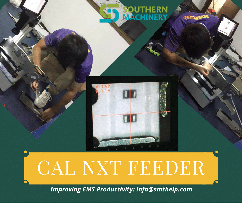
We at Southern Machinery are constantly improving the capabilities for EMS Productivity. We provide the accessories and parts for your needs from various Brands, including Fuji. In the video below we demonstrate a CPK Test for the Fuji NXT W8 Feeder. See how we use these!

We know that your time and productivity are key to a thriving production line. That is why we have made ordering your various AI/SMT spare parts of all BRANDS quick, easy, and secure! Most parts are held in stock and ready to ship with a 1-Day Lead time. Customized parts are also available as well, inquire for turn-around time on your specific customized part needs.

Save

The Automobile Industry is demanding more, have you invested in your SMT Equipment?

Assess Your SMT Equipment Line-up

Is your SMT Equipment Line-up Prepared for Increased Automotive Demands in 2017?

Southern Machinery SMT Feeder

Are you keeping up with SMT demands from the Automotive Industry this year? The demand for automotive electronic products is in direct link with the needs for surface mount technologies. The needs of growing in-car technologies include: embedded infotainment, telematics, connected safety, and security. As car designs continue to become more intelligent and technologically integrated, suppliers must gabapentin online keep up with the ever increasing demands.

It is imperative that PCB manufacturers serving the Automobile Industry assess their current Equipment Line-up for complete preparation of these growing global trends and automobile advancements.  Is your operation ready for full-scale capabilities to serve the Automobile Industry Demands? Would you like to begin manufacturing to supply these needs? Click the link below to contact us for an evaluation of your current operations.

Southern Machinery S-600-OF

Southern Machinery S-600-OF                                         Southern Machine S-600-OF

PC Board Handling Improvements in AI Equipment and Machines

PC Board Handling

Improvements in AI Equipment and Machines

Improve ROI with fast tracking your https://finasteridehair.com current Universal Insertion Machine to an Automatic Board Handling System

Upgrade Universal stand alone auto insertion machine to Automatic Board Handling System

Stay ahead of PCB Manufacturing! The digital curve is constantly bending toward demands for digital devices with increased capabilities and FASTER availability. By using the equipment you already own, you can improve upon its capabilities to meet these growing demands. We will use your current Universal Insertion Machine’s capabilities to transition it to an Automatic Board Handling System that will speed up processes and accomplish maximum PCB production successfully.

We at Southern Machinery have the solution to your distinct Automatic Board Handling needs. Whether you require Magazine-to-Magazine Configuration, Destacker/Conveyor-to-Magazine Loader Configuration, or In-line Configuration, we can serve to improve your PCB assembly line.

Upgrade Universal stand alone auto insertion machine to Automatic Board Handling System

Upgrade Universal stand alone auto insertion machine to Automatic Board Handling System

LED Manufacturing 💡🔦

Bright Idea! Stop importing from China and Invest in LED Assembly Equipment

MARKET DEMAND FOR LED MANUFACTURING

Today, LEDs are used for bulbs and tubes but increasingly they are being used in the many lighting components necessary for automobiles, airplanes, appliances, computers, electronics, televisions and more. LEDs use a whopping 80% less energy than old Incandescent Lighting and 50% less than Compact Fluorescent Lighting. Soon, international mandates to deal with climate change, like the Paris Agreement, will make an already huge market, topple over with growth and opportunity.

LEDs offer a promising solution to deal with energy agendas set forth by conventional international treaties and local environmental policies that seek to gain quantifiable reductions in fossil fuel usage. LEDs are a simple, yet integral solution to improving energy efficiency and helping to solve the issue of climate change. Are you keeping up with the Paris Agreement and what that means for a BOOMING LED Market?

Souther Machinery provides full-service equipment for LED Manufacturing Solutions. Please call us at 0755-83203237 if you would like more information about our LED SMT Manufacturing Technologies and to discuss how we can help you participate in this expanding global market.

Share this Entry

Your PCB Assembly Quality Checklist ✏

We have EVERYTHING you need…

Your PCB Assembly Quality Checklist

After many requests, we are thrilled to announce our Industry Leader Newsletter. As an Industry Leader, Southern Machinery wants to provide your company with the same excellence we put into our equipment and services. We know your job is important and you must always stay ahead of trends in PCB Assembly. Changes in labor costs, shifting environmental laws and policies, energy conservation efforts, advancing industries, international trade politics, etc., are causing a reemergence of in-house manufacturing systems to be put into place. The tide has shifted and it is now time to begin transitioning to a more self-sufficient manufacturing system.

Welcome to our smthelp.net Newsletter! No matter what your company role is, this Newsletter will keep you up-to-date with the most important topics and events that affect the quality and profitability of your manufacturing systems. If it has been a while since we last spoke, stay tuned! We will be delivering important PCB topics to your inbox. In the meantime, we have put a quality checklist together for you!

Your Manufacturing Quality Checklist here:

  • Do you have ROI-Driven Design and Implementation of reliable PCB Assembly Equipment?
  • Is your equipment Low-Cost with High-Intelligence?
  • What is the speed of your PCB throughput?
  • Is your efficiency high?
  • Is your productivity high?
  • Are you increasing your profits by using affordable and reliable equipment?
  • Is your short-term investment low?
  • Is your long-term investment low?
  • Have you eliminated hand insertion for Automatic Insertion for improved time and profits?
  • Finally, have you eliminated your import fees by producing your own PCBs?


Share this Entry


SMT,PEC,UIC,Camera,Balser

UIC SMT machine PEC Camera Assembly – T50319001 Rev

Beam 2 FW PEC Camera Assembly – T50319001 Rev. K
This Document Supports Assembly 50319001 Rev. G


Replace the PEC Camera Assembly

If the PEC Camera Assembly is damaged or experiences an electrical or optical failure, the camera must be replaced.

CAUTION
Use caution when handling the PEC Camera and Lighting Assemblies. These assemblies are very sensitive to sudden shock. Also use ESD precautionary measures when handling the PEC Camera and Lighting Assemblies. A properly grounded ESD wrist strap is recommended.

Prerequisites

Make sure that the following items are available before beginning the procedure:

  • A new PEC Camera Assembly
  • A calibration kit and a new PEC gray card

Remove the PEC Camera Assembly

To remove the faulty PEC Camera Assembly from the head cage, perform the following procedure:

  1. Power down the machine and perform Lockout/Tagout according to local procedures.

WARNING – LOCKOUT/TAGOUT
The machine must be powered down and your site’s Lockout/Tagout procedure executed during this procedure to ensure personal safety.
  1. Open the access cover.
  2. Move the beam to a location where the PEC camera can be easily accessed.
  3. Disconnect the PEC_VIDEO/PWRPL and PEC_LED_CTRPL cables from the Head Cage Interface PCA.
  4. Remove all cable ties securing the PEC camera cables to the head cage.
  5. Remove the PEC camera cables from the cable clamps on the bottom of the head cage.
  6. Remove the screws that secure the PEC lighting to the PEC camera. Let the lighting hang loose from the hole in the carriage plate.

  7. Disconnect the PEC lighting cable from the PEC lighting. Set aside the PEC lighting.
  8. Remove the screws that secure the PEC camera to the carriage plate.
  9. Lift the PEC camera out of the head cage and discard.


Remove/Install the PEC Camera Assembly

If the PEC Camera Assembly is damaged or experiences an electrical or optical failure, the camera must be replaced.

CAUTION
Use caution when handling the PEC Camera and Lighting Assemblies. These assemblies are very sensitive to sudden shock. Also use ESD precautionary measures when handling the PEC Camera and Lighting Assemblies. A properly grounded ESD wrist strap is recommended.

Prerequisites

Make sure that the following items are available before beginning the procedure:

  • A new PEC Camera Assembly
  • A calibration kit and a clean, undamaged PEC gray card

Remove the PEC Camera Assembly

To remove the faulty PEC Camera Assembly from the head cage, perform the following procedure:

  1. Power down the machine and perform Lockout/Tagout according to local procedures.

WARNING – LOCKOUT/TAGOUT
The machine must be powered down and your site’s Lockout/Tagout procedure executed during this procedure to ensure personal safety.
  1. Open the access cover.
  2. Move the beam to a location where the PEC camera can be easily accessed.
  3. Disconnect the camera control/interface cables from the Head Cage Interface PCA.
  4. Remove all cable ties securing the PEC camera cables to the head cage.
  5. Remove the PEC camera cables from the cable clamps on the bottom of the head cage.
  6. Remove the screws that secure the PEC lighting to the PEC camera. Let the lighting hang loose from the hole in the carriage plate.

    (Typical PEC Camera and old-style mount shown below)
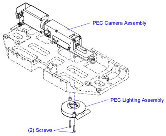

    (New-style PEC mount shown below)


  7. Disconnect the PEC lighting cable from the PEC lighting. Set aside the PEC lighting.
  8. Remove the screws that secure the PEC camera to the carriage plate or mounting block.
  9. Carefully remove the PEC from the head cage.
  10. If installing a camera with a different magnification, remove the 6 frame fiducial inserts on the feeder uprights and the 4 nozzle changer fiducials on the nozzle changer. Retain for use with the .4 MPP PEC camera.

    For UPS+ 7.5SC and higher with a .4 MPP PEC camera: Remove the 6 frame fiducial inserts on the feeder uprights; they will not be re-installed.

Install the PEC Camera Assembly

To install the PEC Camera Assembly, perform the following procedure:

  1. Carefully move the PEC camera into the head cage and position on the alignment pins.
  2. Apply Loctite 222 to the PEC camera mounting screws.
  3. Install the PEC camera mounting screws and torque to 1,36 Nm (12.0 in-lb.).
  4. Connect the PEC lighting cable to the PEC lighting.
  5. Install the PEC lighting to the new PEC camera and secure with the screws removed earlier.
  6. Route the PEC cables through the cable clamps on the bottom of the head cage.
  7. Connect the camera control/interface cables to the Head Cage Interface PCA.
  8. Install new cable ties to secure the PEC cables to the head cage. Do not over-tighten the cable ties.
  9. If installing a .4 MPP PEC camera where one did not exist previously, install the 6 frame fiducial inserts on the feeder uprights and the 4 nozzle changer fiducials on the nozzle changer. Install over the existing fiducials.

    For UPS+ 7.5SC and higher with a .4 MPP PEC camera:  Do not install the 6 frame fiducial inserts on the feeder uprights.

  10. Close the access cover.
  11. Power up the machine.
  12. Determine if the machine is equipped with the Cognex Vision system:
    1. Open Diagnostics II.
    2. Select Version Information > Hardware Options > Vision Systems.

If Cognex Vision is…

Then…

On the machine Continue with the next step.
Not on the machine Do the following:

  1. Update the camera drivers. For instructions, see the Update the Camera Drivers help topic in Voyager.
  2. Continue with the next step after the drivers are updated.
  1. Calibrate the PEC camera and lighting. For instructions, see the PEC Calibration: Camera and Lighting (Multifunction Machines) help topic in Voyager.

PEC Camera Polarizing Components

The PEC camera consists of two elements: a rotating polarizer that covers four of the eight illumination petals and a sliding polarizer. The sliding polarizer is located in the camera aperture. The axis of this polarizer, frequently referred to as the “analyzer”, is orthogonal to that of the rotating polarizer. The combination of these polarizers on the module results in cross-polarized illumination.


(Typical PEC Camera shown)

The rotating polarizer ensures that the substrate is illuminated with linear polarized light. The metal features and ceramic background reflect polarized light differently. The light reflected from the metal has no net change in polarization. Because the orientation of the sliding polarizer located in the camera aperture is orthogonal to that of the rotating polarizer, most of the light reflected from metal features is blocked. Therefore, metal features appear dark on the camera.

In contrast, the ceramic surrounding the metal features randomizes the polarization upon reflection. Because the polarization is randomized, a portion of the reflected light can pass through the central polarizer and reach the camera. Therefore, the ceramic background appears as a shade of gray.

The following table summarizes the polarization effects on metals and ceramics:

Material

Incident Polarization

Reflected Polarization

Central Polarizer Orientation

Intensity at Camera

Metal

Ceramic

Polarized Lighting Zones

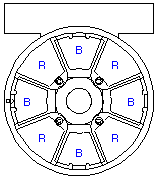
The PEC Lighting Assembly has two lighting zones. Which zones are used for imaging depends on the type of substrate being imaged. The two lighting zones are shown in the table below.

Lighting Zone

LED Color

Graphic

Zone I

Blue

Zone II

Red

Petal Zones I and II each contain four illumination petals positioned at 90 degrees to each other. The illustration below shows how the Red (R) and Blue (B) LEDs are oriented.

Selectable Polarizer Positions

The PEC Lighting Assembly is equipped with a rotating polarizing filter and high intensity LEDs. The PEC camera has a polarizing film mounted within a rotating ring and a second polarizer mounted on a slide above the lighting module. Certain classes of flexible circuits image well with cross-polarized illumination. For the polarized option, it is recommended that the central polarizer be left in place.

  • The blue lighting zone of the PEC Lighting Assembly is designed to image flexible circuits.
  • The red lighting zone of the PEC Lighting Assembly is designed to image ceramic circuits.

The following table summarizes the available Polarized lighting options:

Lighting Zone

Graphic

Function

Zone I

Orienting the rotating polarizer above the blue LEDs allows non-polarized illumination from the Red LEDs. This lighting type is effective on dark-colored ceramics.

Zone II

Orienting the rotating polarizer located above the red LEDs allows polarized illumination from the Red LEDs. This lighting type is effective on white or light-colored ceramics.