
Southern Machinery provides professional SMT peripheral equipment



Surface Mount Assembly Classifications for EMS
Surface Mount Assembly Classifications
Three general classes for the intended end use of electronic assemblies have been established. As applications and functionality increase there may be overlap of equipment between classes. The owner of the application has the responsibility to determine the class that applies. Although a single class may be referenced, specific requirements defined in other classes may apply as well. If a class is not stated for a criterion then the single criterion applies to all classes.
Class 1: Consumer Products: This class of product includes non-critical applications which shall be reliable and cost effective but for which extended life is not the primary objective. Examples include products manufactured for general consumer applications.
Class 2 – General Industrial. This class includes high performance commercial and industrial products in which extended life if required but for which uninterrupted service is not critical. Application and environmental considerations should be taken into account.
Class 3 – High Reliability. Equipment in this class includes those equipment which continued performance is critical, equipment whose downtime cannot be tolerated, or equipment used as a life support item. Unless otherwise specified, Class 3 shall be used for soldering requirements on military electronic equipment.
Printed circuit assemblies are manufactured in a variety of ways, exclusively using smt devices or smt mixed with through-hole components. Boards which have both SMC’s and through-hole components are called mixed technology boards. Surface
mount components are conventionally attached to the substrate using the reflow or the wave soldering process. Typically PCBs are assembled in one of the following ways and categorized as:
Type 1:
SMC’s only are placed on one or both sides of a printed circuit board. The components are attached via the Reflow soldering process.
Type 2:
A combination of both surface mount and insertion mounted components on a printed circuit board. Both SMC’s and IMC’s are assembled on the top side of the board while SMC’s only are attached to the bottom of the board. Top side smt components are Reflow soldered, while the through hole and bottom side smt components are Wave soldered.
Type 3:
IMC’s are assembled on the top side of the board while SMC’s only are attached to the bottom of the board. The components are soldered in place via the Wave solder process.
The fast growth of these applications and advanced packages has led to the development of high density boards. As the industry increases the use of these boards and packages in its products, two of the greatest challenges that it will face are; establishing effective printing guidelines and utilizing equipment that can reliably produce a wide variety of assemblies.
A company’s success or failure in the surface mount industry will weigh heavily on its ability to adapt to automated manufacturing practices through innovative product design and development. Manufacturers can effectively compete in the electronics marketplace today only by utilizing automated equipment throughout the entire SMC assembly process. This includes addressing changes in the SMC production process from initial board printing to final inspection. The companies that do not act positively on these factors and successfully adapt to changing trends in the electronics market will find their business being lost to competitors and foreign ventures.
Type 1 – Single Sided SMT
SMT Components (Primary Side only)
Print Solder Paste Place SMT Components
Reflow Solder
Clean(if required) In Circuit Test/Rework
Surface Mount Process 1-13

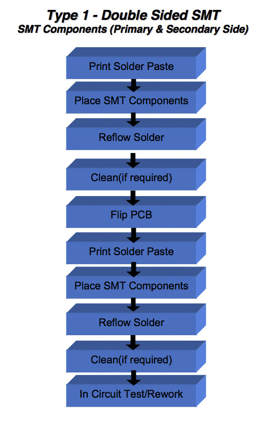
Type 1 – Double Sided SMT
SMT Components (Primary & Secondary Side)
Print Solder Paste Place SMT Components
Reflow Solder
Clean(if required) Flip PCB
Print Solder Paste Place SMT Components
Reflow Solder
Clean(if required) In Circuit Test/Rework
Surface Mount Process 1-14
Type 2 – Mixed Technology
SMT &Through-Hole Components (Primary Side) Passive SMT Components (Secondary Side )
Surface Mount Process 1-15
Squeegee Aperture Paste
On Contact
Frame
Print Solder Paste Place SMT Components
Reflow Solder
Components
Flip PCB
Place SMT Components
Cure Adhesive Flip PCB Wave Solder Clean (If Needed) Test / Repair
Insert / Clinch Through-Hole
PCB
Apply Adhesive (secondary Side)

Type 3 – Mixed Technology Through-Hole Components (Primary Side) Passive Surface Mount Components (Secondary Side )
Flip PCB
Place Surface Mount Components
Surface Mount Process 1-16
Insert / Clinch Through-Hole Components (Primary Side)
Apply Adhesive (Secondary Side)
Cure Adhesive Flip PCB Wave Solder Clean (If Needed) Test / Repair

How to invest LCD TV Final Assembly factory
Volume Requirements
- Total estimated time to complete weekly- production volumes with proposed equipment set = 160 hours/per week (+/- 10%)
Notes:
- Available time is 80 hours (16hours x 5days)!
- Factory efficiency not optimum due to:
- Weekly Scheduling
- Bottle Neck is SM Lines (Top/Bottom)
- Occupation of Lines, High Volume PC’s
- For schedule improvements we propose:
- To add and reconfigure SMT lines, create dedicated HV PC & PC Monitor SM lines
- Increase inventory, make longer runs, increase weekly batches, warming up Factory
IM Lines

- Number of Lines : 3
- Machine Set: Radial S-3000 x 3, Axial S-4000 x 3
- Cycle time: Average 15 seconds
- Intrinsic Availability: 90%
- Mean Time To Repair: 120 seconds
SM Lines
- Number of Lines : 4
- Machine Set: High Speed Chip mounter x 2, IC mounter x 1
- Cycle time: between 12.60 & 25.29 seconds
- Intrinsic Availability: 90%
- Mean Time To Repair: 120 seconds

MI Lines
- Number of Lines : 4
- Machine Set:
- 10 x Assembly stations,each line
- Delta 5 Wave Solder, each line
- 4 x Test & Inspect stations, each line
- Average Cycle Time: 25 seconds

LCD TV FA Lines
- Number of Lines : 2
- Machine Set:
- 16 x Assembly stations
- 3 x L-Shape Soak System 30 min
- Simulation Soak is 30 min with 30 stations x 3
- Final QC/Test and Pack Out, 3 stations
- Two identical Lines (19” to 42”) for optimum Efficiency & Flexibility
- Average Cycle Time: 24 seconds/station


Why SMT? How to EMS?
Why SMT?
Manufacturers continuously evaluate new components and systems technologies in terms of reducing size, increasing design flexibility, improving reliability and reducing cost for systems. SMT satisfies all these requirements. It can provide size reductions of over 40%, assembly cost reductions of almost 50%, and can enhances the performance of electrical circuitry [Lea, 1988].
SMT Reduces Size and weight
The increased density of components can lead to a higher functionality in the same space. This allows the system manufacturer to price differentiate his product in the market by carefully choosing his components.
- SMT components require less circuit board area and volume than their through-hole equivalent.
- Components can be mounted on both sides of boards.
- Lighter components with the same functionality can be significant in the
aerospace industry as well as portable consumer electronics.
SMT Increases Performance
- SMT offers better interconnectivity due to shorter paths, providing lower inductance and capacitance.
- SMT reduces the package propagation delay, which is the time the signal needs to move from one component to another. Typically the longest delays in the system are off-chip.
- Electromagnetic interference can be decreased by combining sensitive circuits on a single board and improving its Electromagnetic Induction (EMI) shield design.
SMT Improves Reliability
- The smaller and lighter construction of SMC’s allow them to resist shock and vibration better than their through-hole counterparts.
- The reduced number of PCBs and connectors improves overall reliability at the system level.
- However, SMT systems require careful attention to mechanical design to avoid overstressing the solder joints.
- The demanding nature of the SMT process has resulted in extensive automation and corresponding increases in product quality.
-
SMT Reduces Cost
• Bare Boards
The use of SMT, typically, results in smaller area PCBs being used due to the reduction in the size of the components being used. In general for two functionally equivalent PCBs, one utilizing surface mount and the other using conventional through hole, the larger the PCB, the more expensive it will be. Increased density on an SMT board generally requires multiple layers as well as smaller line widths and spacings to accommodate the finer pitch components and smaller hole diameters to interconnect the layers. The only time a hole is required is to carry the signal to another layer whereas with through hole components there must be a hole for each lead of each component. In some cases through hole PCB’s may require more layers because there are more larger holes which means there will be less room on the inner layers for circuit routing increasing the layer count.• Processing
Surface mount components have almost all been designed for automatic assembly. Many unusually shaped, through-hole components, called odd- formed components, which were designed for hand assembly, can now be placed automatically as well. Automated assembly of surface mount assemblies can be done using one flexible automated placement machine whereas several machines may be required for the various through hole components.
As more types of components become available in a surface mount format, correspondingly fewer components are available in through-hole configuration forcing the cost of many SMC devices down. While through-hole components can be automatically inserted, the combined equipment, floor space and processing costs are higher.
• Factory Operating
Fewer types of assembly machines are required for an SMC assembly line and they often requires less floor space. Automated SMT assembly lines are considerably more productive than PTH assembly tools. Thus throughput is raised considerably with SMT manufacturing and the cost per unit of assembly is greatly reduced.
SMT Increases Flexibility
- SMT provides a wider range of packaging possibilities than insertion mount technology.
- SMT allows for the use of both surface mount and insertion mount devices in the same assembly.
SMT Eases Handling And Storage Space Needs
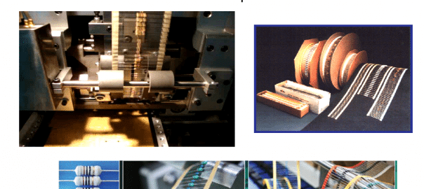
Surface mount components are easy to handle due to the various storage formats in which they are shipped and presented to the pick and place machines. Tape and reel, cartridge, sticks, magazines, and matrix trays allow effective and safe handling and shipping. The storage formats have the following features:
- Large number of components per packing unit resulting in less frequent loading of the tools.
- Small amount of packing materials per component resulting in lower shipping and inventory costs.
- Protection against transport and handling damage.
- Standardization, Definite orientation of the components.
- Protection against electrostatic discharge resulting in fewer defective systems
and rework.
- Compatible with highly automated equipment.
Electronic Industry Organizations and Groups
Uniform Standards for Surface Mount Technology are still under development in the USA, Europe and Japan. Although much has been accomplished, there is still no single set of industry guidelines. However, efforts are being taken to resolve this problem. For example, there was inconsistency in the standards set by the IPC and the EIA. As this was recognized, they have joined forces to set up a council called Surface Mount Council, to coordinate the various standards between the users and the developers of these standards. These documents have a J-STD- xxx designation. Moreover, other organizations like the International Microelectronics and Packaging Society (IMAPS) are working together on the technical issues in the PCB industry. These developments are promising and should lead to a common industrial standard in the near future.
IPC- Association Connecting Electronics Industries
2215 Sanders Road Northbrook, IL 60062-6135 USA Tel: (847) 509-9700 Fax – (847) 509-9798
Internet: www.ipc.orgIn 1999, IPC changed its name from Institute of Interconnecting and Packaging Electronic Circuits to IPC. The new name is accompanied with an identity statement, Association Connecting Electronics Industries.
IPC started in 1957 as the Institute for Printed Circuits. As more electronics assembly companies became involved with the association, the name was changed to the Institute for Interconnecting and Packaging Electronic Circuits. In the 1990s, most people in the industry could not remember the name and/or didn’t agree on what the words in the name meant. In addition, the leaders from government or other business groups could not understand the name either.
