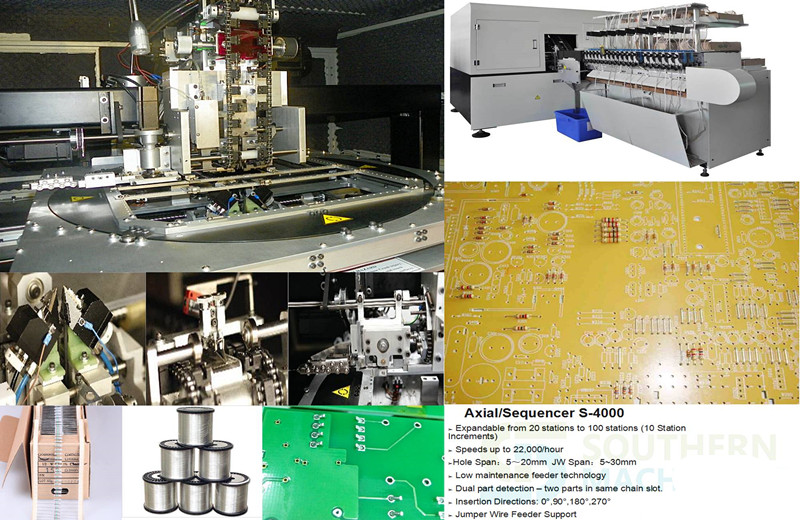
Southern Machinery provides professional SMT peripheral equipment

Auto Insertion machine Tooling Design vs. Range of Inserted Component Wire
1.0 INTRODUCTION
Do you have customers who are willing to simplify the Axial automated insertion process, speed up machines, lower preventative maintenance (pm) downtime and ppm levels and generally reduce manufacturing costs? If so, then this paper may interest you.
Universal Instruments Corporation is currently working to customize tooling for customers who have evolved their manufacturing processes to two and three step processes for Axial insertions, thereby dedicating machines to run a limited range of components. In step one for example, a machine inserts only 5mm insert spans and then in step 2, a second machine inserts various wire diameters. This is a radical change from the current manufacturing philosophy of fully populating a board in one pass through a machine. However, history has shown that by limiting the range of wire diameters inserted and then designing tooling to specifically handle that range, the manufacturing process becomes more controlled, insertion performance improves, pm downtime and ppm levels decrease and ultimately, manufacturing costs decrease.
Admittedly, this approach is not viable for every customer. Universal offers a variety of tooling configurations that if used according to specification, will provide excellent insertion performance. A customer may have no need to run a wide range of wire diameters or they may want to revisit their manufacturing process to make improvements. For those customers, Universal offers customized tooling for dedicated applications. Customized tooling will handle a limited range of wire diameters to optimize insertion performance and maximize tooling life.
This paper discusses the relationship between tooling design and wire diameter range of inserted components with the goal of creating an awareness and understanding of this relationship and it’s significance.
2.0 FACTORS AFFECTING THIS RELATIONSHIP
2.1 Depth of V-Groove of Outside Former
One important factor affecting the relationship of tooling design and range of insertable wire diameters is the depth of the V-groove of the Outside Former. Our current specifications for Axial tooling are as follows:
|
|
Standard |
High Density |
Large Lead |
5mm |
26mm AAA |
|
Bottom View of Outside Former |
|
|
|
|
|
|
Wire Diameter Range / Material |
Steel: .015”-.032” (.39) – (.82) Copper: .015”-.032” (.39) – (.82) |
Steel: .015”-.025” (.39) – (.64) Copper: .015”-.032” (.39) – .82) |
Steel: .025”-.032” (.64) – (.82) Copper: .025”-.042” (.64) – (1.01) |
Steel: .015”-.025” (.39) – (.64) Copper: .015”-.028” (.39) – (.72) |
Steel: .015”-.020” (.39) – (.51) Copper: .015”-.024”(.39) – (.61) |
|
Driver Tip Width |
.030” (.77) |
.030” (.77) |
.050” (1.27) |
.017”* (.44) |
.012”* (.31) |
Metric equivalents are bracketed
* Not entire width but dimension from edge of Driver Tip to side of Outside Former
When the wire diameter is smaller than the depth of the V-groove of the Outside Former, the lead has excess space and moves within the V-groove. This uncontrolled condition leads to a ‘weak’form.
|
|
|
V-groove with Small Lead Diameter
When the wire diameter is larger than the depth of the V-groove of the Outside Former, the yieldable Inside Former flexes to make room for the bigger lead. Continual flexing causes the O-rings to wear out which leads to a ‘sloppy’Inside Former and ‘weak’forms. Outside Formers have been known to split at the V-groove from continual stress. Long term, continual flexing will damage the Tooling Housing by loosening it and making it ‘sloppy’.
|
|
|
V-groove with Large Lead Diameter
The optimal condition is wire diameter equal to the depth of the V-groove of the Outside Former. In this condition, the lead is large enough so that is does not ‘move’within the V-groove, and yet it does not continually flex the Inside Former.
|
|
|
V-groove with Optimal Lead Diameter
When Standard tooling is compared to 5mm tooling, it becomes clear why 5mm tooling is less reliable when inserting components with large lead diameters than Standard tooling.
|
TOOLING |
DEPTH OF V-GROOVE |
WIRE DIAMETER RANGE |
|
Standard |
.028”(0.71mm) |
.015”-.032”(0.39mm – 0.82mm). |
|
5mm |
.018”(0.46mm) |
.015”- .028”(0.39mm – 0.72mm) |
The depth of the V-grooves vary by .010”(0.26mm) and yet the range of wire diameter is very similar.
2.2 Radius of V-Groove of Outside Former
Another factor is the radius of the V-groove of the Outside Former. The V-groove is actually a radius of .016”(0.41mm) for all tooling types except large lead tooling which is .019”(0.49mm). Because this is a radius, not a diameter, the optimum lead size for this size radius is .032”(0.82mm) This radius creates a situation that allows a small wire diameter to ‘roll around’or be uncontrolled in the groove. A true V-groove improves this condition by creating a 2 point contact.
|
|
|
|
One Point Contact |
Two Point Contact |
2.3 Body Length to Insertion Length
Body length to insertion length is another critical issue in this discussion. The bigger the gap between the component body and the bend of the lead, the more room there is for the insertion tooling. As the Driver Tip descends, it can damage a component body that is too long for the specified insertion span. Clearance is also needed for the Inside Former coming beneath the bend of the lead. A bend too close to the component body can also cause damage. Maximum body length is obtained with the following formula:
Programmed Z-Span = Insertion Span + 1 Lead Diameter
Maximum Body Length (clearance between Driver Tips)
= Insertion Span + 1 Lead Diameter – 2 x Depth of Outside Former V-groove – 2 x Driver Tip Thickness
Do not use components with body lengths at the maximum length. Allow .020”(0.51mm) on each side of a component body for clearance and to account for tolerances.
|
|
|
|
Component Body Leaving Clearance |
Component Body Leaving No Clearance |
2.4 Driver Tip Position
During a component insertion, the Driver Tip rests on the horizontal surface of the lead. When a lead has a ‘weak’form, the Driver Tip rests on top of the bent portion of the lead. As the Driver Tip tries to push a component through the holes of the pc board, it has a tendency to ‘slide off’a lead, leading to a standup or failed insertion. This is true of 5mm tooling because of its small Driver Tip.
|
|
|
|
Driver Tip Position during insertion |
Driver Tip position during insertion of weak form lead |
3.0 SUMMARY OF ABOVE CONDITIONS
· Wire diameters significantly smaller than the depth of the V-groove of the Outside Former are uncontrolled within the V-groove. This is caused by one point contact and excess space, which leads to a ‘weak’form and poorly controlled insertion. Small lead components without a ‘crisp’form are also at risk of misinserting because the Driver Tip may ‘slip off’the lead, while pushing it through the pc board. This condition is seen most often with 5mm tooling.
· Wire diameters significantly larger than the depth of the V-groove of the Outside Former continually flex the yieldable, Inside Formers causing premature tooling wear-out of the Inside and Outside Formers as well as other parts of the tooling.
· Acceptable component body length varies with Z-span, but clearance is required for the Inside Formers and Driver Tips during insertion so the component body is not damaged.
4.0 OPTIMAL CONDITIONS
To optimize insertion performance and maximize tooling life, it is best to limit the range of wire diameters inserted with any tooling selection, keeping in mind the optimal wire diameter is the same size as the V-groove of the Outside Former. For example, if the wire diameter range of a particular application is .018”- .022”, a .020”V-groove is optimal. This eliminates the problems mentioned above and allows optimal tooling life, process control and low insertion ppm.
Making use of the squeeze function when writing pattern programs can also help. If a component lead diameter is small in relation to the V-groove of the Outside Former, the squeeze function can improve a ‘weak’form. The squeeze function is also useful when inserting steel leaded components as they tend to have a memory after the forming process. It also helps insert components with long bodies and a small insertion span.
Allow clearance on each side of a component body so there is room for the insertion tooling.
Consider dedicating a manufacturing line to a particular application for optimal performance and then customize the tooling for a small range of wire diameters. Universal offers customized tooling for dedicated applications. Customized tooling can include the following items, as needed:
2 point contact in V-groove of Outside Former based on an optimum lead diameter
Increase size of Outside Former footprint for a more robust design
Improved bent lead input insertion capability
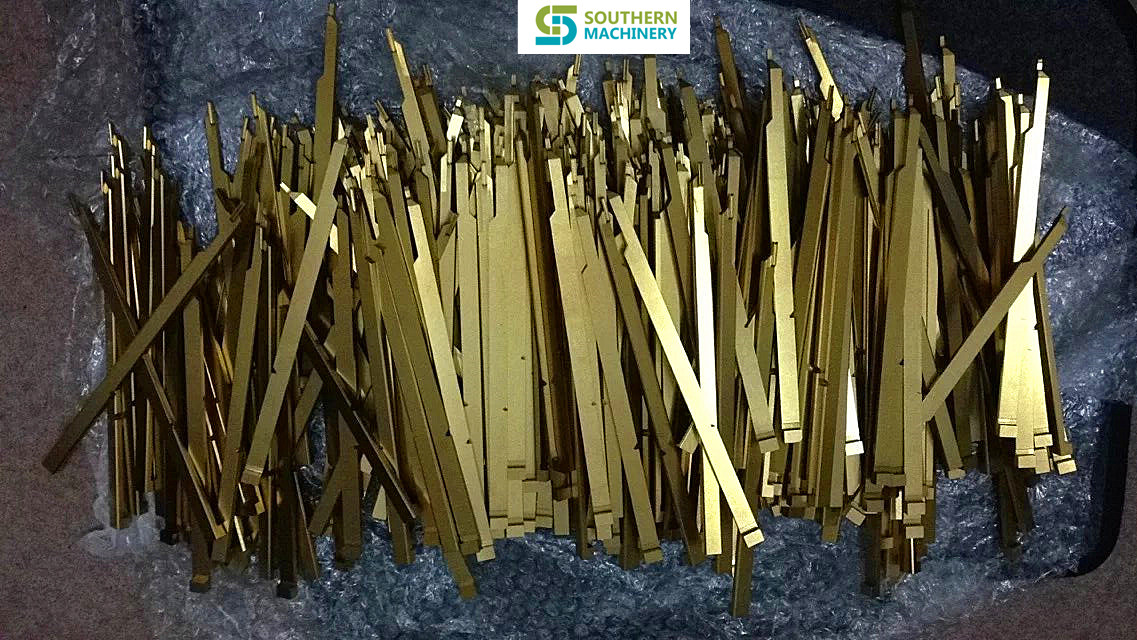
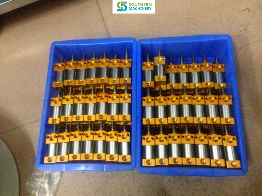
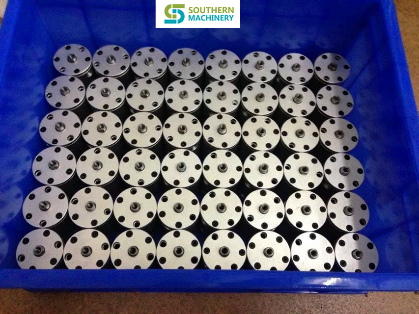

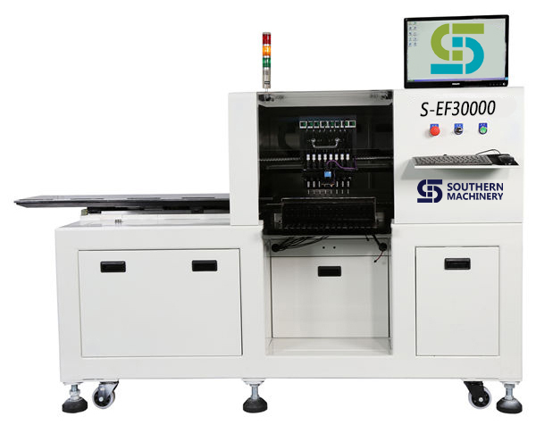
Southern Machinery LED SMT machine S-EF30000 vs Topaz XiII Comparision
| Southern Machinery S-EF30000 vs Topaz XiII Comparision | ||||||

|
Model | S-EF30000 | Topaz XiII | Result | ||
| No. | Item | (Southern Machinery Advantage) | ||||
| 1 | Spec Speed | 36,000 CPH | 18,000 cph | double speed, double throughput | ||
| 2 | PCB Size | Max: 1200×390mm | Max: 460×440 | Special design for 1.2m LED tube | ||
| 3 | flexible PCB | yes, no need fixture | need special make a fixture | Suitable for flexible PCB strips | ||
| 4 | PCB loading | Manual | Approximately 3 sec. | saving PCB loading time | ||
| 5 | Applicable components: | 0603 to 7474 | 0201 – SOP, SOJ, PLCC 32mm | Suitable for all LED lighting products | ||
| 6 | Machine Config | 8 Spindles x 1 Gantry | Simultaneous pick with 8 spindles | |||
| Fixed Vision Alignment System | ||||||
| 8 |
Mounting accuracy: (X,Y) 3σ |
±0.05(3δ) | ±0.10(6δ) chips | ± 75µ for chips and SOIC | totally enough for LED Chips | |
| 9 | Mounting angle: | 0 up to 360 | 0 up to 360 (in steps of 0.01) | |||
| 10 | Number of feeders: | 16 (12mm) | 8mm: 90 positions | |||
| 11 | Machine dimensions : | 2,000(L) x 1,150(D) x 1,350(H) | 1,650mm(L)x1,408mm(W)x1,850mm(H) | |||
| 12 | Machine weight: | Approx. 950kg | 1,600Kg | |||
| 13 | Maintenance Cost | less $1000.00 per year | $2000.00 per year | |||
| 14 | Machine price | $35,000.00 | $70,000.00 | at least saving 50% money | ||
| 15 | Performance / Price | 1.03 | (36000/35000) | 0.26 (18000cph/$70000) | ||
| 16 | Conclusion: | 5 times throughput / cost Advantage to use S-EF30000 produce LED product | ||||
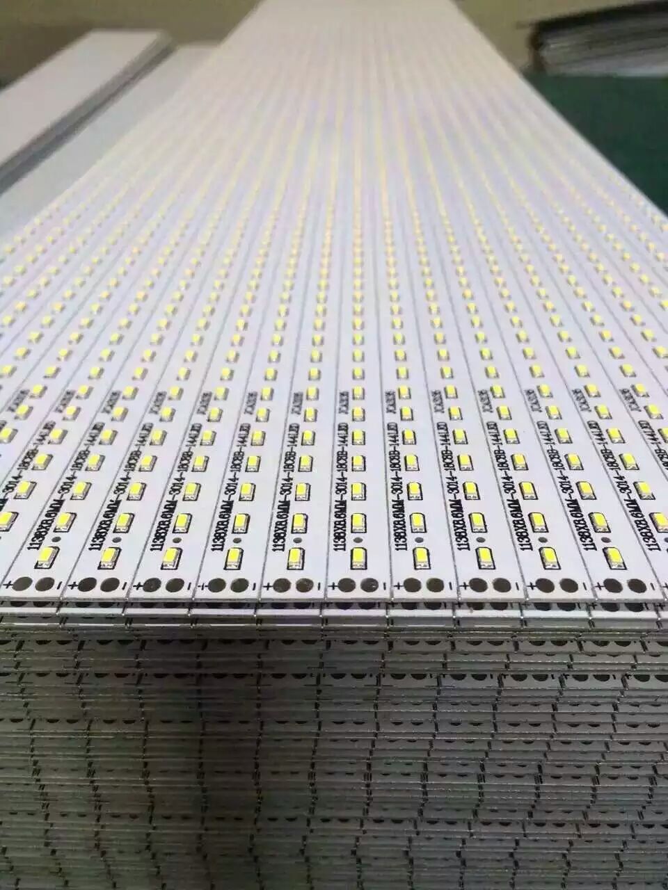
How to gang place in LED pcb assembly
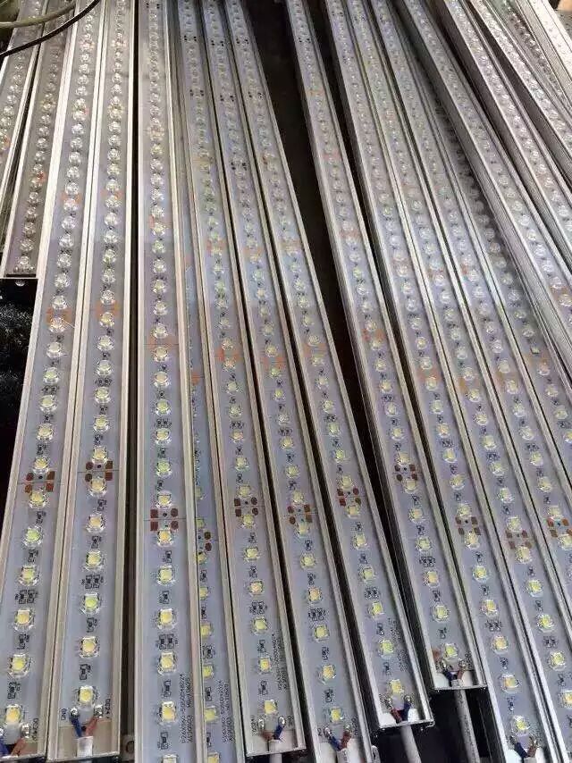
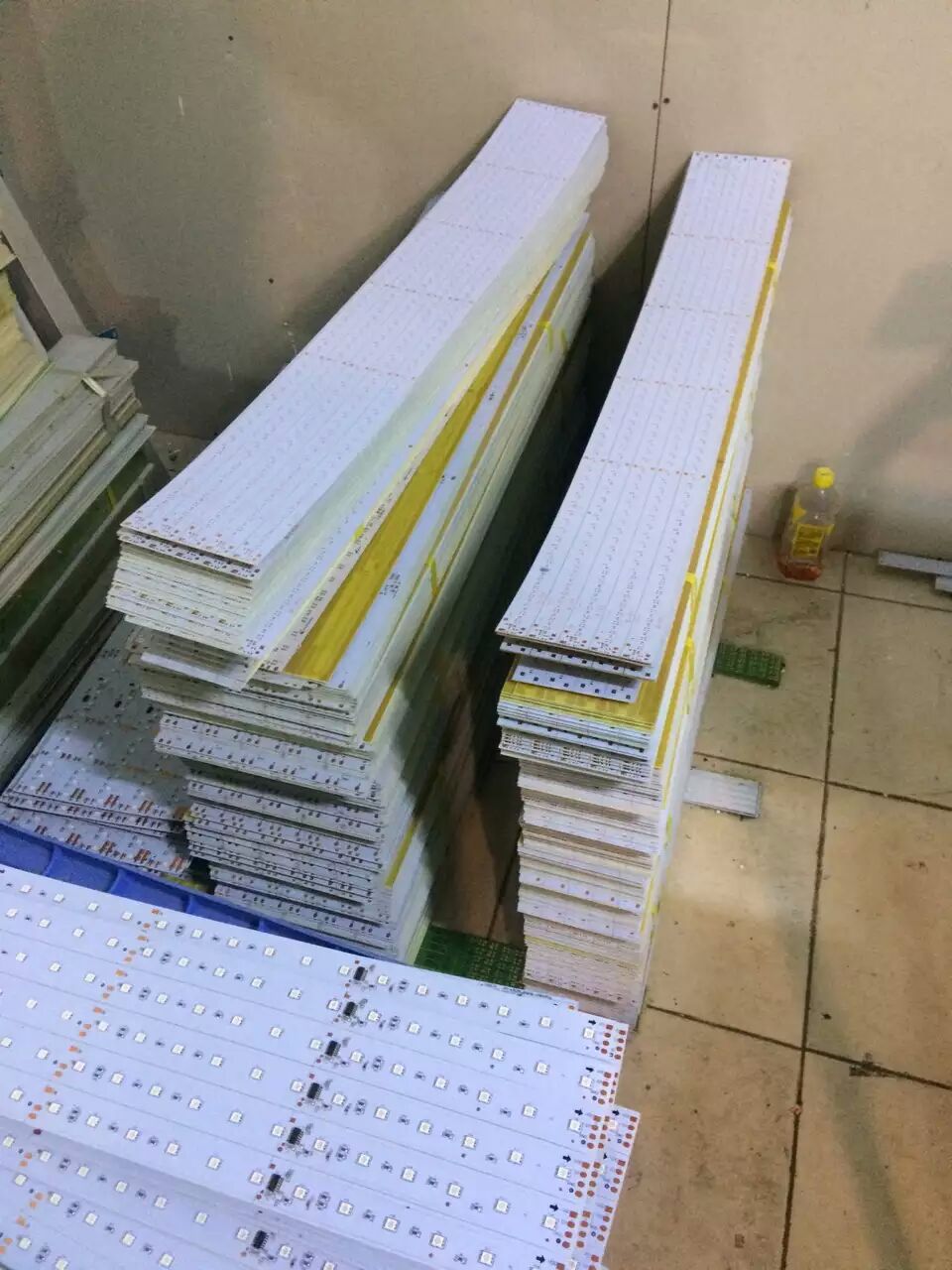
For cost-saving or technical reasons (such as improved assembly), multiple circuit boards may be combined to form one large board, a “panel”. This panel is then produced just as a single large http://bestacnedrug.com circuit board. Consult with us to design the distance of LED chips is same as the spindle distance of placement head.

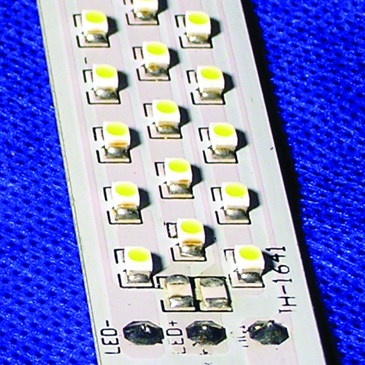

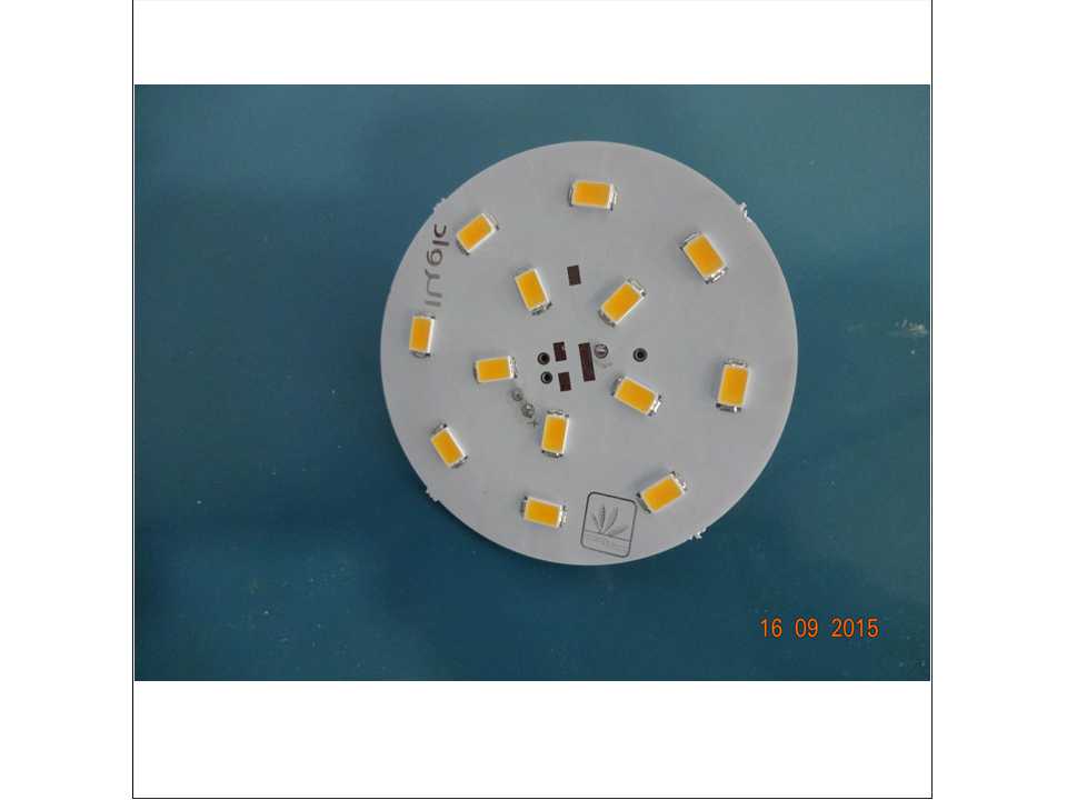
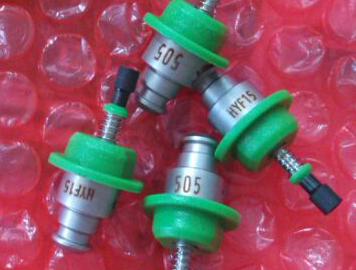
Why not Nozzle exchange for LED pick and place machine
1. As we consider that many customers products don’t have so many kinds of components in a board .
2. For example ,though in a board ,there are about 20 kinds of different components,but the size of many components are nearly . Sometimes just need about 3-4 kinds of nozzles is ok.
3. Besides, our S-EF30000 have 8 spindles, can install 8 kinds of different nozzles at a time,has mostly satisfied customers’ requirements of production , but also save machine’s cost for them .
4. As per your production ,if no need to install so many kinds of nozzles at a time and change the nozzles automatically frequency , if we add a alternate pick up nozzle tray on our machine ,won’t it add your cost of the machine?
5. We won’t suggest you to buy our most expensive and with too many functions machine to increase your cost if your production no need.
Vision System application for LED pick and place machine
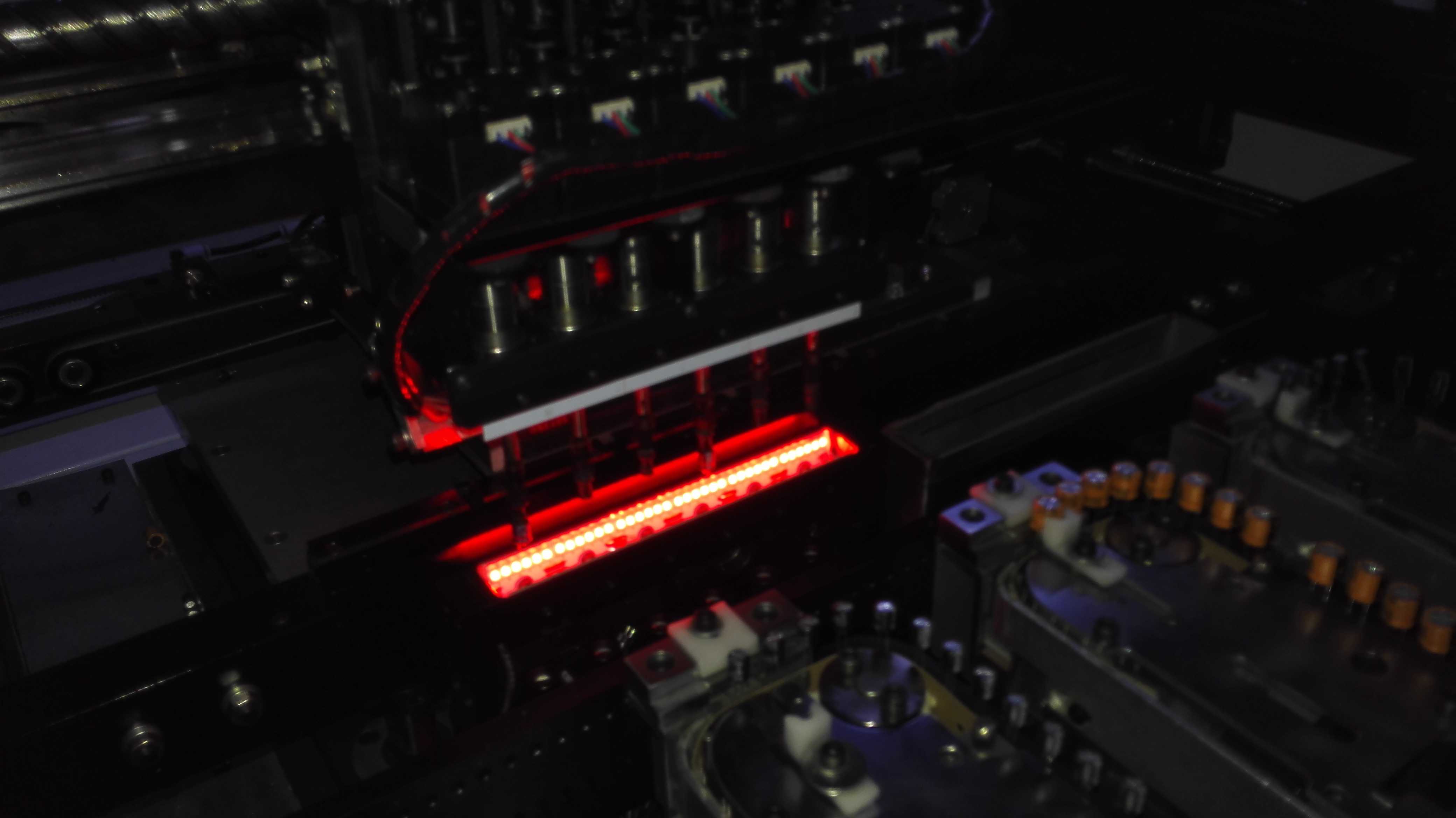
1)Visual registration system
(2) Laser detection registration system .
Both have different characteristics, so there are differences in the use.
Comparison:
Laser detection registration system:
Laser counterpoint to allow flight correction, capable of handling all shapes and sizes of components, and can accurately determine element position and direction, but, even more complex laser systems cannot measure the pin and pin spacing.
Visual registration system :
The visual system is able to judge the position and orientation of components and can measure http://trueviagraonline.com lead and lead spacing at the same time .In addition, the visual system does not need to adjust the system will be able to adapt to the update components encapsulation, thus has better flexibility.
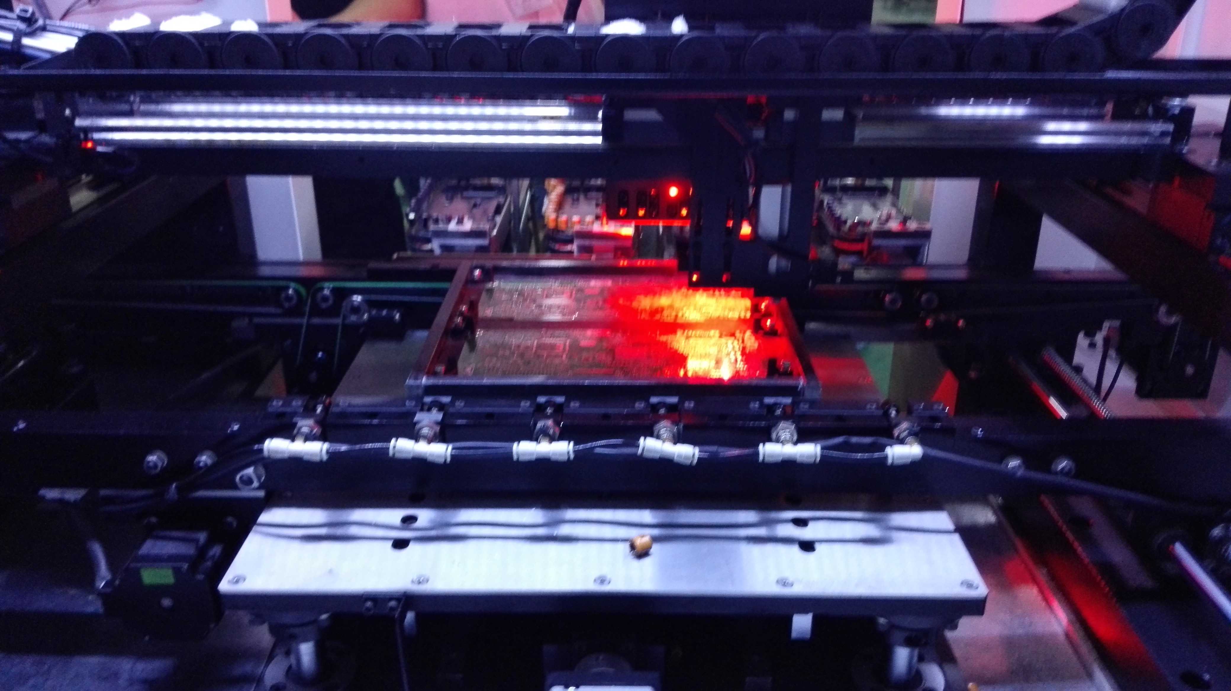
All of Southern machinery the Pick & Place machine config with vision system
Worldwide 7×24 service online support
$50000 SMT Line for LED Products Assembling
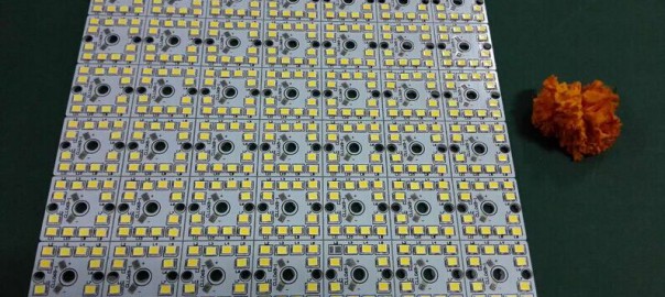
This line is designed specially for beginning manufacturers of LED lighting systems.
Special nature of LED systems production is the necessity to have high speed equipment for various LEDs and minimal set of SMD components.
The line is based on architecture of a standard line for SMD component assembly, but the equipment is modified specially for work with LEDs.
The oven length allows working with long aluminum PCBs (with high heat capacity) according to temperature profile recommended by LED vendor, without decreasing of operation time for the rest of the line.
Special vacuum nozzles are used for placing LEDs on PCBs; they are designed to avoid damage of their silicone lens. These nozzles are made of non-adhesive materials to avoid sticking of lens.
The unique ability of the line is work with LEDs in bulk; that could lower the cost of purchased components as well as the final cost of the product.
the photo below is one of our custmer

One SMT line equipments Investment of : $120k & Profit: $50K per month
Easy way – Easy http://buylevitra.net profit with One SMT line equipments Investment of : $120k & Profit: $50K per month
How to save 10 times cost on wearing spare parts?
We have the most original spare parts drawing,with our good quality materials,can help you to save your cost by about 10 times comparing with original spare parts. Why don’t you have a try about our spare parts? We will satisfy you 100%.
AI,SMT wearing spare parts ,like UIC AI parts, Fuji,Samsung,Juki,YAMAHA and so on ,nozzle,feeders.




Are you still running TDK auto insertion machine
Below pare parts for TDK radial insertion machine, welcome inquiry.
[table id=15 /]
