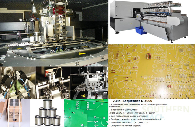
Southern Machinery provides professional SMT peripheral equipment

Auto Insertion machine Tooling Design vs. Range of Inserted Component Wire
1.0 INTRODUCTION
Do you have customers who are willing to simplify the Axial automated insertion process, speed up machines, lower preventative maintenance (pm) downtime and ppm levels and generally reduce manufacturing costs? If so, then this paper may interest you.
Universal Instruments Corporation is currently working to customize tooling for customers who have evolved their manufacturing processes to two and three step processes for Axial insertions, thereby dedicating machines to run a limited range of components. In step one for example, a machine inserts only 5mm insert spans and then in step 2, a second machine inserts various wire diameters. This is a radical change from the current manufacturing philosophy of fully populating a board in one pass through a machine. However, history has shown that by limiting the range of wire diameters inserted and then designing tooling to specifically handle that range, the manufacturing process becomes more controlled, insertion performance improves, pm downtime and ppm levels decrease and ultimately, manufacturing costs decrease.
Admittedly, this approach is not viable for every customer. Universal offers a variety of tooling configurations that if used according to specification, will provide excellent insertion performance. A customer may have no need to run a wide range of wire diameters or they may want to revisit their manufacturing process to make improvements. For those customers, Universal offers customized tooling for dedicated applications. Customized tooling will handle a limited range of wire diameters to optimize insertion performance and maximize tooling life.
This paper discusses the relationship between tooling design and wire diameter range of inserted components with the goal of creating an awareness and understanding of this relationship and it’s significance.
2.0 FACTORS AFFECTING THIS RELATIONSHIP
2.1 Depth of V-Groove of Outside Former
One important factor affecting the relationship of tooling design and range of insertable wire diameters is the depth of the V-groove of the Outside Former. Our current specifications for Axial tooling are as follows:
|
|
Standard |
High Density |
Large Lead |
5mm |
26mm AAA |
|
Bottom View of Outside Former |
|
|
|
|
|
|
Wire Diameter Range / Material |
Steel: .015”-.032” (.39) – (.82) Copper: .015”-.032” (.39) – (.82) |
Steel: .015”-.025” (.39) – (.64) Copper: .015”-.032” (.39) – .82) |
Steel: .025”-.032” (.64) – (.82) Copper: .025”-.042” (.64) – (1.01) |
Steel: .015”-.025” (.39) – (.64) Copper: .015”-.028” (.39) – (.72) |
Steel: .015”-.020” (.39) – (.51) Copper: .015”-.024”(.39) – (.61) |
|
Driver Tip Width |
.030” (.77) |
.030” (.77) |
.050” (1.27) |
.017”* (.44) |
.012”* (.31) |
Metric equivalents are bracketed
* Not entire width but dimension from edge of Driver Tip to side of Outside Former
When the wire diameter is smaller than the depth of the V-groove of the Outside Former, the lead has excess space and moves within the V-groove. This uncontrolled condition leads to a ‘weak’form.
|
|
|
V-groove with Small Lead Diameter
When the wire diameter is larger than the depth of the V-groove of the Outside Former, the yieldable Inside Former flexes to make room for the bigger lead. Continual flexing causes the O-rings to wear out which leads to a ‘sloppy’Inside Former and ‘weak’forms. Outside Formers have been known to split at the V-groove from continual stress. Long term, continual flexing will damage the Tooling Housing by loosening it and making it ‘sloppy’.
|
|
|
V-groove with Large Lead Diameter
The optimal condition is wire diameter equal to the depth of the V-groove of the Outside Former. In this condition, the lead is large enough so that is does not ‘move’within the V-groove, and yet it does not continually flex the Inside Former.
|
|
|
V-groove with Optimal Lead Diameter
When Standard tooling is compared to 5mm tooling, it becomes clear why 5mm tooling is less reliable when inserting components with large lead diameters than Standard tooling.
|
TOOLING |
DEPTH OF V-GROOVE |
WIRE DIAMETER RANGE |
|
Standard |
.028”(0.71mm) |
.015”-.032”(0.39mm – 0.82mm). |
|
5mm |
.018”(0.46mm) |
.015”- .028”(0.39mm – 0.72mm) |
The depth of the V-grooves vary by .010”(0.26mm) and yet the range of wire diameter is very similar.
2.2 Radius of V-Groove of Outside Former
Another factor is the radius of the V-groove of the Outside Former. The V-groove is actually a radius of .016”(0.41mm) for all tooling types except large lead tooling which is .019”(0.49mm). Because this is a radius, not a diameter, the optimum lead size for this size radius is .032”(0.82mm) This radius creates a situation that allows a small wire diameter to ‘roll around’or be uncontrolled in the groove. A true V-groove improves this condition by creating a 2 point contact.
|
|
|
|
One Point Contact |
Two Point Contact |
2.3 Body Length to Insertion Length
Body length to insertion length is another critical issue in this discussion. The bigger the gap between the component body and the bend of the lead, the more room there is for the insertion tooling. As the Driver Tip descends, it can damage a component body that is too long for the specified insertion span. Clearance is also needed for the Inside Former coming beneath the bend of the lead. A bend too close to the component body can also cause damage. Maximum body length is obtained with the following formula:
Programmed Z-Span = Insertion Span + 1 Lead Diameter
Maximum Body Length (clearance between Driver Tips)
= Insertion Span + 1 Lead Diameter – 2 x Depth of Outside Former V-groove – 2 x Driver Tip Thickness
Do not use components with body lengths at the maximum length. Allow .020”(0.51mm) on each side of a component body for clearance and to account for tolerances.
|
|
|
|
Component Body Leaving Clearance |
Component Body Leaving No Clearance |
2.4 Driver Tip Position
During a component insertion, the Driver Tip rests on the horizontal surface of the lead. When a lead has a ‘weak’form, the Driver Tip rests on top of the bent portion of the lead. As the Driver Tip tries to push a component through the holes of the pc board, it has a tendency to ‘slide off’a lead, leading to a standup or failed insertion. This is true of 5mm tooling because of its small Driver Tip.
|
|
|
|
Driver Tip Position during insertion |
Driver Tip position during insertion of weak form lead |
3.0 SUMMARY OF ABOVE CONDITIONS
· Wire diameters significantly smaller than the depth of the V-groove of the Outside Former are uncontrolled within the V-groove. This is caused by one point contact and excess space, which leads to a ‘weak’form and poorly controlled insertion. Small lead components without a ‘crisp’form are also at risk of misinserting because the Driver Tip may ‘slip off’the lead, while pushing it through the pc board. This condition is seen most often with 5mm tooling.
· Wire diameters significantly larger than the depth of the V-groove of the Outside Former continually flex the yieldable, Inside Formers causing premature tooling wear-out of the Inside and Outside Formers as well as other parts of the tooling.
· Acceptable component body length varies with Z-span, but clearance is required for the Inside Formers and Driver Tips during insertion so the component body is not damaged.
4.0 OPTIMAL CONDITIONS
To optimize insertion performance and maximize tooling life, it is best to limit the range of wire diameters inserted with any tooling selection, keeping in mind the optimal wire diameter is the same size as the V-groove of the Outside Former. For example, if the wire diameter range of a particular application is .018”- .022”, a .020”V-groove is optimal. This eliminates the problems mentioned above and allows optimal tooling life, process control and low insertion ppm.
Making use of the squeeze function when writing pattern programs can also help. If a component lead diameter is small in relation to the V-groove of the Outside Former, the squeeze function can improve a ‘weak’form. The squeeze function is also useful when inserting steel leaded components as they tend to have a memory after the forming process. It also helps insert components with long bodies and a small insertion span.
Allow clearance on each side of a component body so there is room for the insertion tooling.
Consider dedicating a manufacturing line to a particular application for optimal performance and then customize the tooling for a small range of wire diameters. Universal offers customized tooling for dedicated applications. Customized tooling can include the following items, as needed:
2 point contact in V-groove of Outside Former based on an optimum lead diameter
Increase size of Outside Former footprint for a more robust design
Improved bent lead input insertion capability
AI spare parts


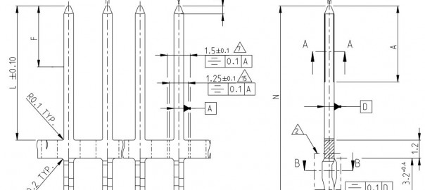
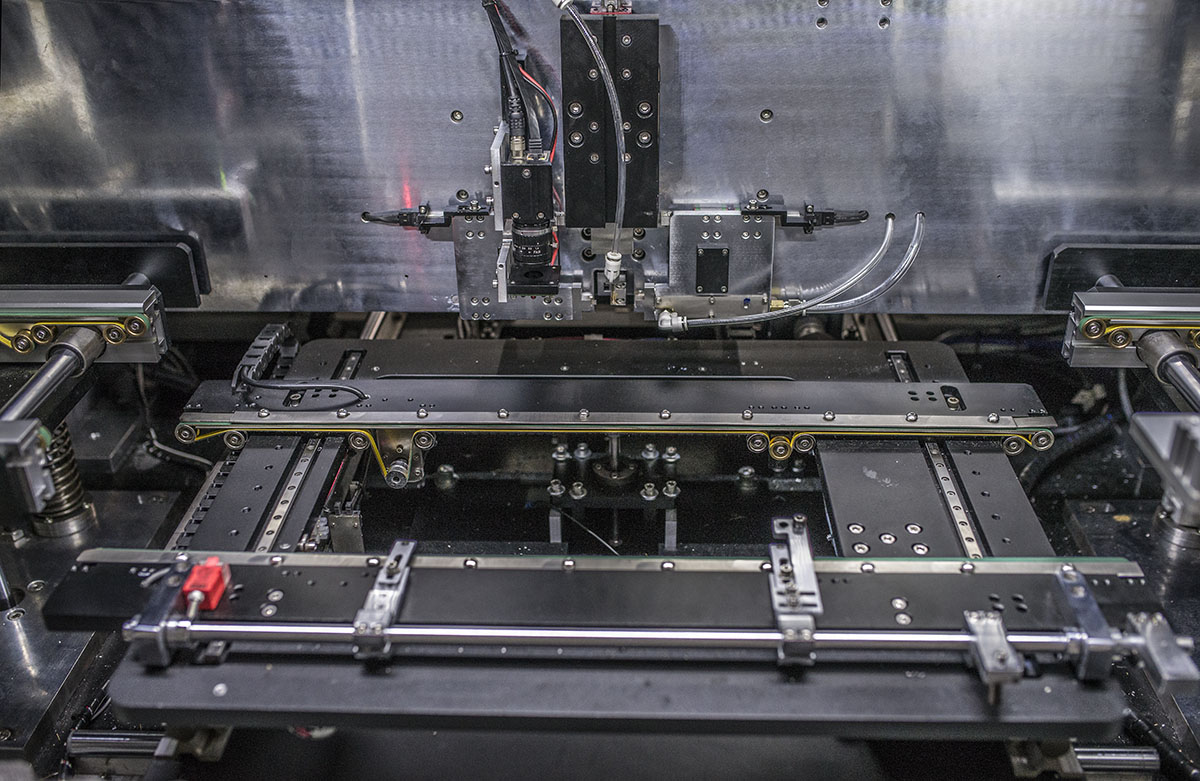
S-7000 Full Automatic Pin Inserter
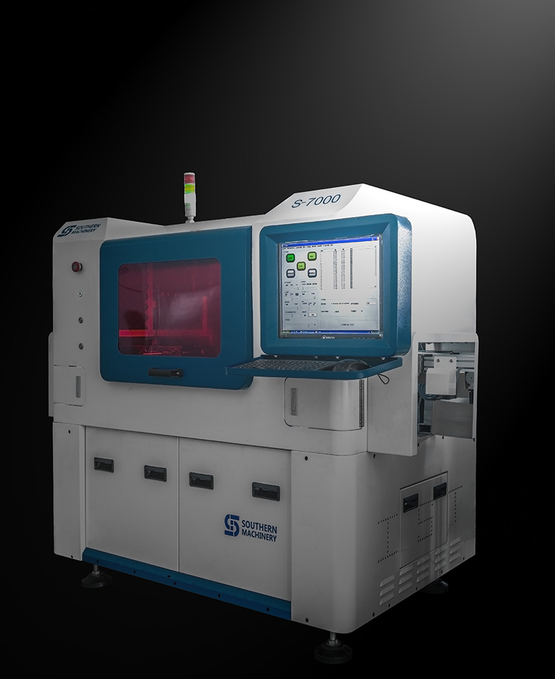
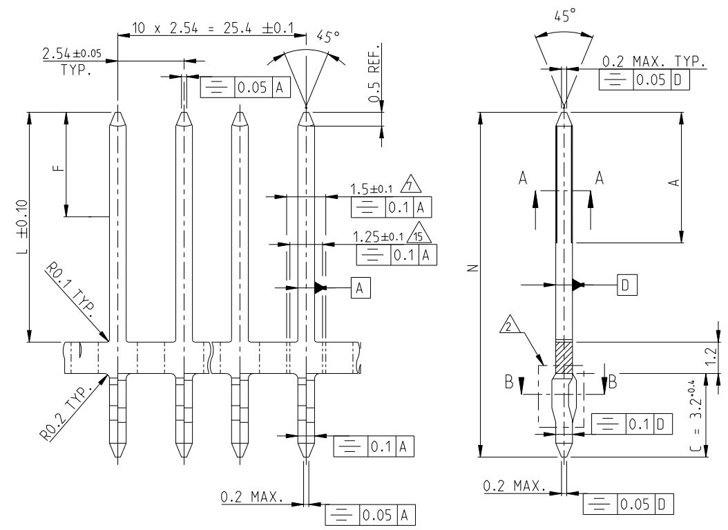
The S-7000 pin inserter is a custom-made model for square pin insert.
PC control,servo motor drive,vision programming.SMEMA connector.

|
Speed |
12,000 CPH Spec |
|
PCB Size |
Max. 480mm * 480mm |
|
PCB Thickness |
0.76-2.36mm |
|
Insert Head |
1 |
|
Machine dimension |
2300mm*1340mm*1860mm (L*W*H) |
|
Machine weight |
1500KG |
|
Power supply |
Single Phase 220VAC, 50/60HZ, 1.0KVA |
|
System Protection |
UPS |
|
Air pressure |
0.4-0.6Mpa (Round pin 0.55-0.6Mpa)/0.3M3/Min |
|
Data input |
USB interface input (EXCEL format) |
|
Control System |
English version interface (WINDOWS system control platform) LCD monitor |
|
PCB transfer mode |
automatic load / unload |
Want more information,pls leave a comment
5 Reasons for you to choose LED SMT assemble line from Southern Machinery
24 hours online service for LED SMT assembly machines:

1)What is high speed SMT pick and place machine ?
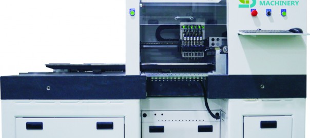
The high speed automatic SMT mounting machine is the equipment used to realize high-speed, high accuracy completely automatic mounting the electric elements like LED light sphere, electric resistance , electric capacity etc. It is the mot essential and most complex equipment in the entire SMT production. The mounting machine is the major machine in SMT production line, and it is already developed from the early low speed mechanical mounting machine to high-speed optics mounting machine, and to multipurpose, flexible connection modulation development.
2)What machines does the LED board processing need ?
The LED mount technical process simplification is: Printing, Pick and placing, Reflow Oven (in each part, you can join examine link to control quality)
3) What are the advantages of Southern Machinery SMT pick and place machine ?
a.Top high speed in the world, quick than the main SMT machines brands like Siemens, Fuji, Samsung, Panasonic, Sanyo;
b.Lowest power consumption, 2.5-3.5KW/Hour;
c.Match vacuum pumps along with the main machine, no need to match extra vacuum pump;
d.Electric control system is installed on the top of the main machine, easy to maintain, and has a good damp proof effect;
e.Integrated forming steel frame, guarantee our mounting machine a stable performance on high speed running conditions.
f.The distance of sucking mouth can be adjusted manually, photoelectric will make sure the accuracy after adjust, allow you to mount different pitches PCB board.
4) What kinds electric elements can use our high speed SMT machine !
The main elements our machine can mount include: LED lights, electric capacity and electric resistance, sizes like: 0805,1206,2121,2835,3014,3528,5050,5630,5730,RGB; mainly for 1.2-1.5 meter LED light tube, LED panel light, 0.5-1.0 meter LED light strip , RGB strip.
5) What is our main business scope ?
We are the leading manufactuer of SMT LED mounting machines in Shenzhen, China, and we can produce and supply you all the SMT processing needed machines to you, mainly include: LED PCB board mounting machine, PCB board printer, PCB board reflow oven , and other related SMT devices.
For more detailed information about our LED SMT assemble line, email us freely, and you are warmly welcomed to visit our factory for SMT devices business !
What service you can enjoy if you purchase machine from us:
-
1. AI/SMT PCB Design Guidance
- How to improve machine’s efficiency,save more workers for you.
- Starting from the PCB layout and component specifications.
- Considering the potential of equipment,
- how to make the machine’s actual speed to be theoretical.PCB size ,
- how to custom can make more efficient
-
2. AI/SMT Technology Process Of Import
- First insert or pick&place?Step-by-step to guide you for designing your PCB production process.
- The new product programming, transfer line, how to deal with many varieties of small batch ?
- How to reduce the production process defective rate?
- Improve the continuous optimization
-
3. Equipment’s installation And Technology Training
- What position does your equipment should be installed in the workshop?
- Teach you how to layout the workshop for most conforms the technological process, save workers.
- Care about the more precise assembly and installing your equipment more than you.
- Equipment installation before/after have comprehensive training courses.
- We have English training courses and years of experience to install abroad.
- We not only training the AI/SMT machine, we study together, progress together.
- 4. Machine Trouble Shooting/Retrofit/Overhaul/Relocating
- Equipment production status 7X24 hours in the Cloud End, managers “anytime” “anywhere” insight into equipment production, state;
- Factory technical experts can 7 x24 hours online video consultation equipment technical fault, the cloud initiative to monitor and remind equipment maintenance;
- We upgrade your machine, you increase your productivity;
- And maintenance of the annual/full access to our professional engineer, they well, you must be able to get beyond your expectations of harvest;
- 5. AI/SMT Machine Accessories
- Equipment 7 x24 hours in the “cloud”, we offer equipment spare parts list according to equipment real-time state, and supported the use of PC equipment direct orders to buy;
- We have many years of AI/SMT machine accessories design, production and manufacturing experiences;
- We service life of spare parts, as well as spare parts affect the quality of the products for machinery and equipment and , and that, we willing to help our customers;
- We not only provide wearing parts replacement, more willing to provide you with technical guidance;
- We have professional engineers to electronic boards, motors and so on to provide maintenance services.
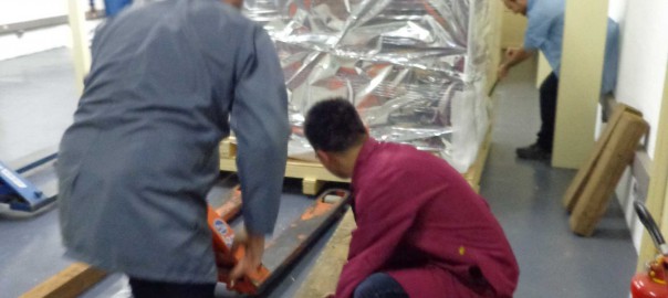
5 years Experience of The Southern Machinery’s Global Services
Welcome to southern machinery, your complete Information Distribution and E-learning Solution Center. We provide a full spectrum of engineering, technical, industrial, and training support services, data and voice/video communications services for clients nationwide and overseas. Our professional, certified staff can provide you with innovative and cost-effective solutions.
Southern machinery’s standard development process involves detailed review of customer requirements by our global applications engineering team. We work with you to develop and deliver a complete PCBA manufacture system optimized to the needs of your end application. Our extensive engineering expertise team can guide you through prototyping, testing, tool development and production.Our svervice engineers provide before/after sales support and facilitate all communication with our design centers.
Our approach is flexible and accommodating; our highly trained and experienced engineers will travel all over the world to solve your on-site problems making it possible for you to have a worldwide customer base who have complete confidence in your products.
The on-site presence provided by Southern machinery gives you cost effective but consistent and effective support for your products.
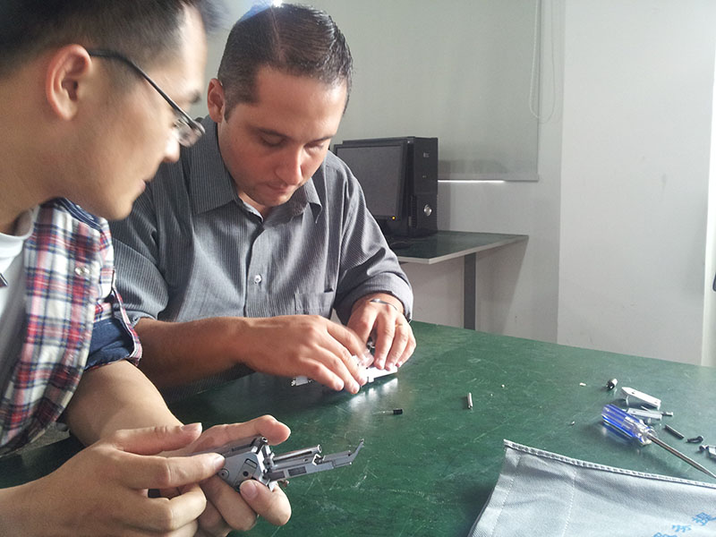 Ecuador customer training in training centre
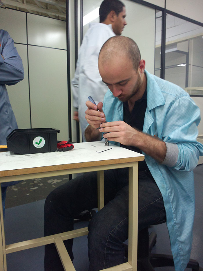 Brazil customer on-site training
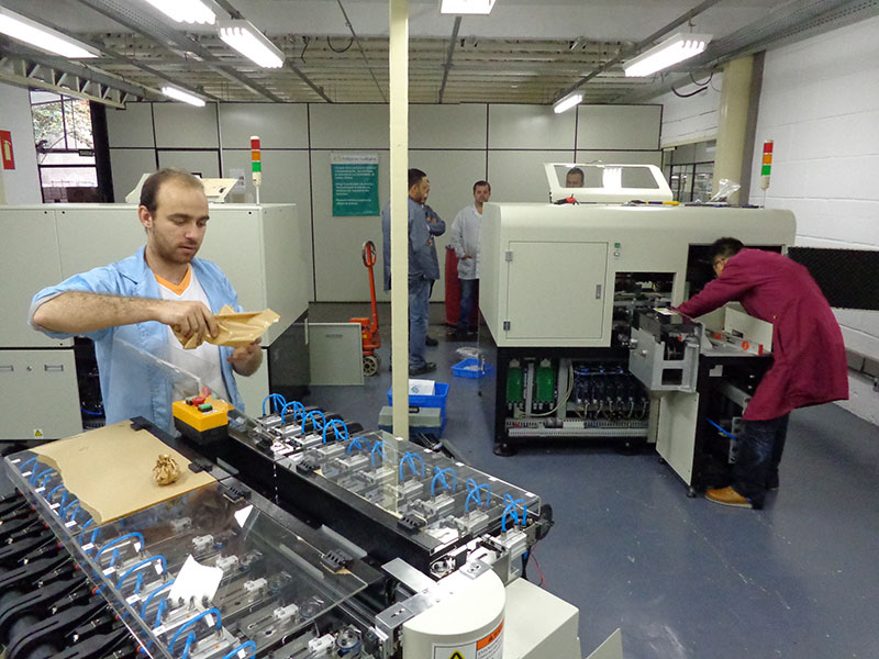
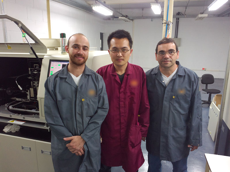 our engineer set up the machine in Brazil
 our engineer set up the machine in Saudi Arabia
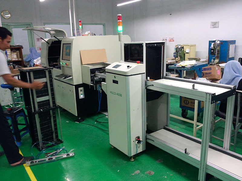 our machine in Indonesia customer
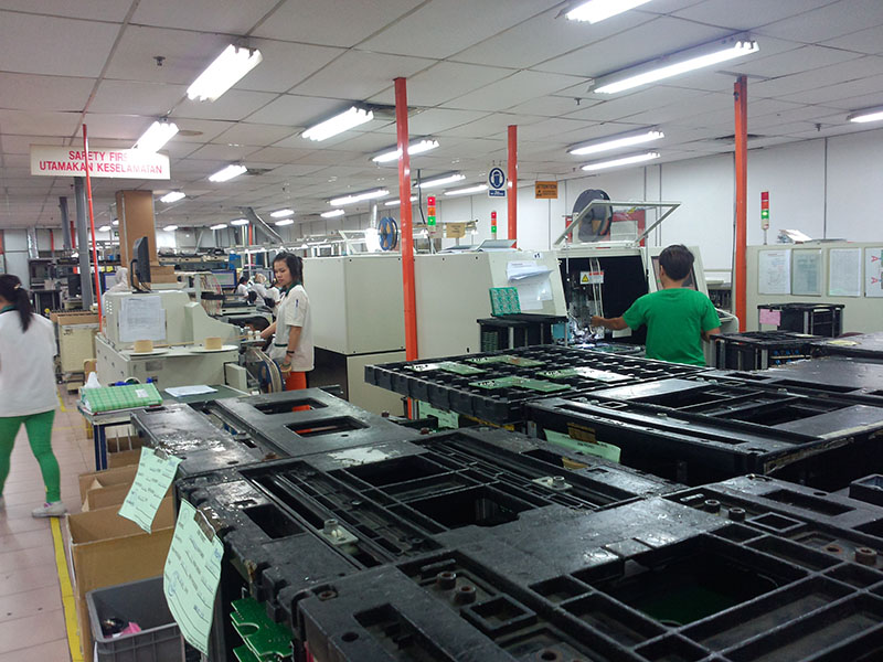 our machine in Malaysia customer

 our engineer set up the full led manufacture line in India customer
From The Southern Machinery’s Global Services.
3 points development trend of SMT LED machine
THE DEVELOPMENT TREND OF THE LED MACHINE
The LED pick and place machine play an important role in manufacturing process, is the contemporary mainstream electronic assembly technology investment the largest and the most advanced production equipment, the production ability of SMT production line, and the greatest influence the efficiency of production equipment. In fact, the most fault, speed bottleneck largely from patch the process, so the development of the placement machine equipment is the most conspicuous. Currently has the number of SMT machine and advanced level, has become a corporate, regional, or national key symbol of electronic manufacturing capacity. Facing the current development trend of the placement machine under declare as follows.
1? the LED pick and place machine is developing toward the higher precision
Placement machine precision is refers to the placement machine X, Y axis navigation movement of the mechanical precision and Z axis rotation accuracy. SMT machine adopts precision mechanical and electrical integration technology control the mechanical movement components will crawl out from the feeder and after calibration institutions for the precise and reliable loaded on the circuit board. In order to produce the products with higher performance, first of all, facing a major challenge is more likely to improve placement accuracy of SMT machine. Below from the LED process began to speak with a higher accuracy of the LED placement machine could have LED the revolutionary impact of production in the future.
With the launch of the flip chip bonded technology, both are linked together by more stable metal convex welding ball to connect, saves the cost and greatly improves the reliability and the cooling capacity. Leads have the advantages of long service life, cooperate with the flip chip bonded technology is better than the traditional packaging technology of gold wire interconnection can play the advantages of LED, LED inversion welding technology, to realize the single chip and multichip module without gold line, solid crystal gel encapsulation, high brightness, high luminous efficiency, high reliability, low thermal resistance, good color uniformity, and many other advantages.
LED no gold wire packaging industry commonly known as the “packaging” encapsulation “free”. This process is to use the flip chip and PCB SMT joint directly, SMD encapsulation process is omitted, the flip chip directly with SMT method on the joint to the circuit board or bearer, because the chip http://www.onlinepharmacytabs.com area is far less than the SMD components, so the process need to be very sophisticated design.
LED placement machine in improving accuracy of future conditions on the basis of applied directly to the flip chip packaging process, it will be little revolution LED process, can save a lot of packaging costs, and greatly improves the production cost and shorten the production cycle, really high performance LED products to enter the general lighting market at low price. Will the LED placement machine directly applied to the LED process, very has the potential to become future technology trends.
2? the LED pick and place machine is developing toward the high efficiency production
Today, however, one of the most important characteristics of competition. It’s this competition, inspire people to explore innovation; It’s this competition, promote the development of science and technology with each passing day. In the course LED lighting market in full swing, the LED placement machine of high efficiency work must become its core competitiveness. High efficiency is to raise the production efficiency, reduce working time, increase production, create economic benefits. On the basis of the current main methods of improving efficiency are: strengthening the LED placement machine, automatic performance and improving the device structure and working mode.
3. the LED pick and place machine intelligent direction development
With the rapid development of Internet technology, the explosive growth of mobile intelligent terminal and consumer groups of young, intelligent is inevitable in the development of electronic industry especially in home appliance industry, the concept of intelligence has been frequently appear in our life, intelligent product is the most promising market in the future. Similarly, in the manufacturing, intelligent manufacturing equipment is the most promising manufacturing technology development.
Intelligent LED SMT machine has the following characteristics: man-machine integration, self-study, self-organization, maintenance, such as self-healing, super flexible, high automation level, improves the mental Labour to reduce the error in the process of production, so as to promote efficiency increase production capacity. Future LED placement machine is on the basis of computer intelligence technology makes his classes with more advanced thinking ability, to stick to the whole process of loading analysis, judgment, reasoning, and decision making, and can through the collection, storage, sharing and inherit the human experts’ intelligent and efficient to quickly provide the most suitable for flexible scheme. LED placement machine, motors and intelligent is bound to the LED production and technology have a great effect in the future.

“Southern Machinery – World’s Choice for SMT/THT Machines & Spare Parts”
“Southern Machinery – World’s Choice for SMT/THT Machines & Spare Parts”
