How SMT workshop planning? It turned out to be so useful.
How SMT workshop planning!
And only after the plant began production found that some areas have not planned beforehand, need to be adjusted, resulting in a waste of human and financial resources and valuable production time.
Therefore, it is important to check in advance SMT factory layout, especially for new SMT factory business, because there is no experience in SMT plant layout, the need to pay attention to the elements is not very clear, if we find a problem in the layout after production point, will cause some unnecessary losses.
So, when doing layout SMT plant, what to pay attention to what matters in advance to do to prepare? Here actual cases where we work to and we explore this problem.
Case
planning SMT line configure
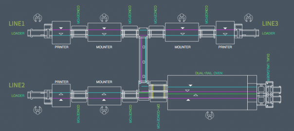
the client recent planning new on two identical SMT production line, specific device configuration (see FIG. 1) and the size of the apparatus is as follows: According to Figure 1 can be seen, the maximum width of the production line equipment is 1.71 m, the length of all devices sum is 13.6 meters, will add future planning a production line (line bulk on equipment configuration).
Situation Workshop
Workshop length 36 m, width of 12 m, an area of 432 m2, on the ground floor of the factory. Currently common ground for the shop floor, and no established anti-static system, can not meet the requirements of SMT antistatic workshop, but two conductive ground terminals, can establish subsequent workshops antistatic SMT system. Further, there is no air conditioning workshop and humidifiers, can not meet the requirements of SMT workshop temperature and humidity control. There workshop ventilation system, back to meet the requirements of the reflow furnace equipment. Workshop sufficient power to meet the electricity needs of all equipment in the workshop. There are two entrances whole plant, as are required to meet the equipment, raw materials and semi-finished channel. Special materials warehouse in another workshop, the need for planning. Good lighting conditions in the workshop, to meet the brightness of the SMT shop lighting requirements all stations. Whole plant layout situation shown in Figure 2.
Customer requirements
1, the current new move into production lines and related aids, regional positioning;
2, the whole plant to meet future erection and production requirements three production lines, without planning zone realignment;
3, each production line starting position as consistent as possible, so that the whole plant orderly arranged in three lines.
Subject of
analysisthe customer’s request, we first analyzed how the production line positioning; and before locating the production line, we consider the following points:
1, SMT equipment should avoid column and they maintain a certain distance, the distance is equipment installed at least after a good feed material by a vehicle;
2, SMT crossing equipment required for frame division pitch, and the crossing equipment to extend outwardly after the device installed above the material 50 cm;
3, optimal spacing of the two lines spaced more than 1.2 meters between the outer frame;
4, check the wire tail is generally a repair plan area, quality control personnel can perform sampling line tail region.
Based on the above considerations, the length of each line should be at least 13.6 meters (without regard to the maintenance area and the tail, the case where the sampling area and the thread area kanban), the width should be 2.7 meters (SMT feeding both surfaces), specifically as shown in Figure 3.
Therefore, the production line is positioned in substantially considering plant shown in FIG. 4.
Some details of the requirements of SMT plant layout
after determining the approximate location of the production line, when the need to consider some details of SMT production line requirements, and then to determine the exact location and the location of other auxiliary equipment SMT line.
First, we analyzed the SMT line position and aids required for each area requirements: 1, fire extinguisher drop zone;
fire extinguishers to be placed around the side of the post and SMT plant, placed according to the requirements of fire regulations.
2, the car rack placement region; car rack replacement for SMT production line models and switching material, in order to facilitate production and to improve the efficiency of replacement materials, preferably the vehicle is placed near the rack placement machine.
3, stock units rest area;
stock table mainly used in the production process and dryer materials stock preparation before switching, therefore, to be placed near the preparation station placement machine, and the best car rack together, Preparation facilitates directly on the car frame after a good feed material.
4, the shelf rest area printing station;
printing station for positioning the shelf aids in the production of printing presses, such as wipes, paste, alcohol, etc., to be placed in the vicinity of the printing press to facilitate removal use, improve Productivity.
region comprising placing solder paste storage refrigerator, solder paste mixer, paste warmed cabinets, can be placed next to the plant as required or uprights placed around a fixed area of the plant, However, to facilitate the operator to take place.
6, visual inspection after the furnace area, maintenance area;
in order to facilitate visual inspection after reflow and rework semifinished product, a shelf generally placed in the furnace, designed for the visual inspection of the furnace and rework.
7, screen placement area;
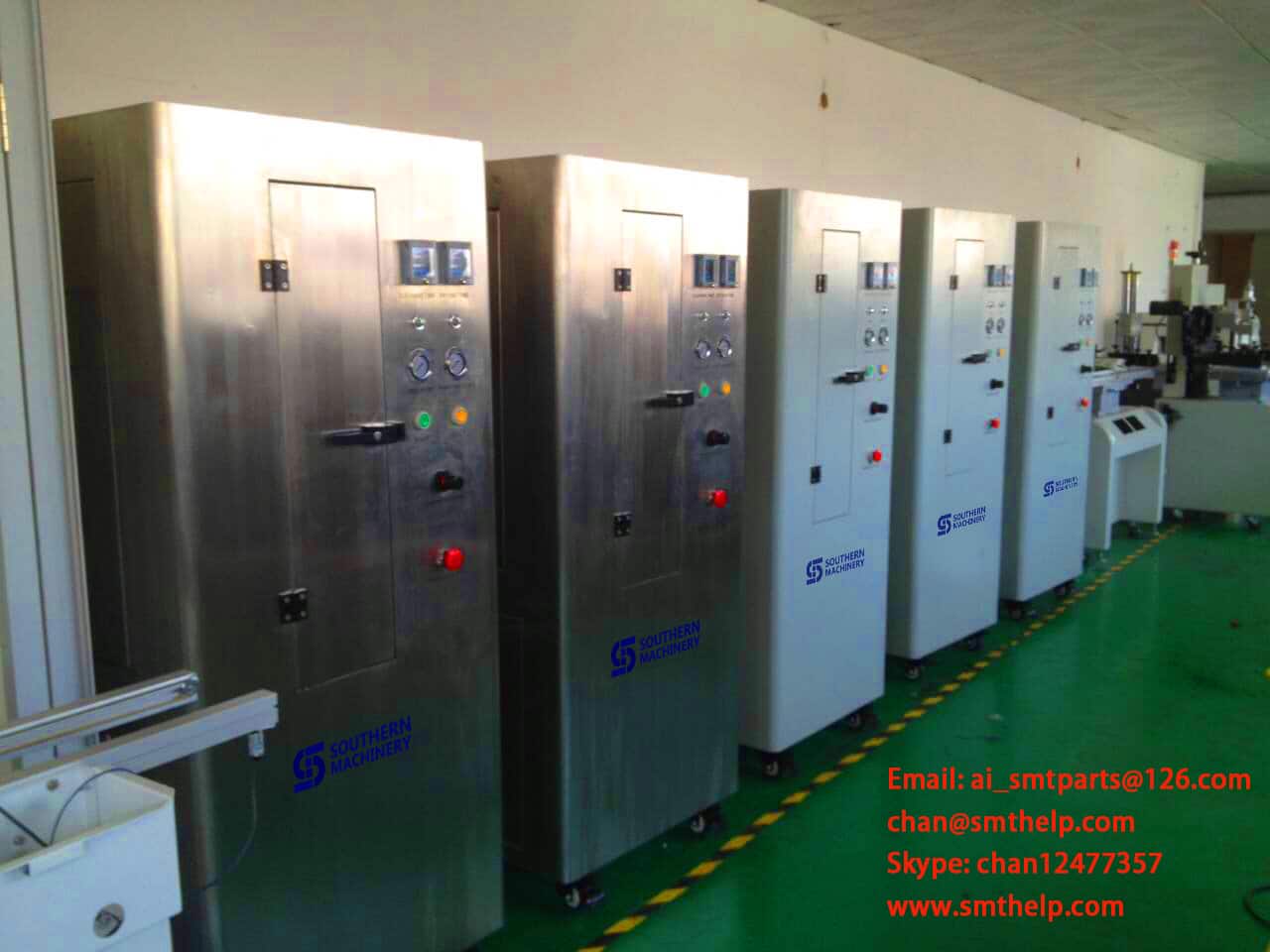
drop zone comprises a mesh screen plate was placed cabinet, stencil cleaningmachine, inspection tools, screen, stencil for storing, cleaning and inspection screen tension, etc., while in the region as much as possible to facilitate the production screen to take place.
8, garbage drop zone;
Production waste mainly from two parts, wipes and the like used in one printing operation, the second is to replace the waste tray and waste material produced with the like. Garbage two parts is generated to be placed separately, specialized recycling, in particular waste presses used. Thus, waste area may be placed next to the press machine or patch, or set beside the column region refuse placed separately placed.
9, kanban placement region;
kanban including the SMT billboards and other signage quality management, may be centrally located on the entrance into the shop, and also set up the production line Kanban state in which each head of the line, in order to view the producers and managers, promptly understand the current state of production status and quality SMT workshop and so on.
10, product placement area;
include products produced finished products in two parts, to separate the two partial regions divided out, strictly distinguished, in order to avoid confusion.
11, SMT placement of spare areas;
Nozzle including the SMT spare parts, a motor, a belt, cylinder or the like, to be placed in a special area, to facilitate the production of access.
12, location area temperature and humidity;
temperature and humidity conditions in order to better understand the SMT plant, depending on the size of the workshop area, several appropriately set the temperature and humidity measurement area, generally placed on the production line next to the column or wall.
13, SMT workshop office area;
let engineers and technicians and management personnel in office SMT shop floor, which can solve the problem on technology and management encountered in the production, to ensure the smooth operation of the SMT production lines.
14, anti-static protection area;
entry into SMT workshop area must have good anti-static measures. You may delineate the area in front of the plant, including the replacement of static clothing, shoes, hats and so on each employee’s locker. Also, the establishment of regional designed to test the static ring in SMT workshop at the entrance, so that each employee to do static loop testing and record test results before going to work. Based on the above analysis, the results of this SMT plant layout is shown in Figure 5.
In addition, SMT workshop also meet other requirements: 1, anti-static processing;
shop floor must be anti-static treatment, a common anti-static conductive flooring and paint and other ordinary places, customers can choose according to the actual situation. In addition, anti-static system must be set up in the workshop, to meet the requirements of the entire anti-static SMT workshop.
2, air-conditioning and a humidifier; SMT workshop to meet the requirements of temperature and humidity control.
3, the material management requirements;
in the warehouse, with particular attention to the way the material is stored, reel packaging methods, the use of hook-type place, wetting elements employed Cabinets for placement shelves to be treated with anti-static manner.
4, patch equipment gas and electrical circuitry;
preferably introduced directly from the production line at the down side of the roof, is arranged below the gas passage in the device and circuit wrapped with wire groove.
5, the ventilation system requirements;
needs to be installed to meet the requirements of the three power lines of the blower, and the third exhaust port reserved line.
Results
1, according to the size of production line and the size of the entire plant SMT, completed the reasonable position of the production line; and
2, for aids, regions, etc. SMT production lines need to make the corresponding position location; 3, according to the SMT the characteristics of the plant, some of the necessary factors to consider in planning, in particular, anti-static; 4, in accordance with the requirements of the current situation and future development of the factory has been take into consideration, unified planning.
Summary
For SMT plant layout, but also requires a combination of size and product requirements and other plants to consider a number of factors, but to stimulate here.
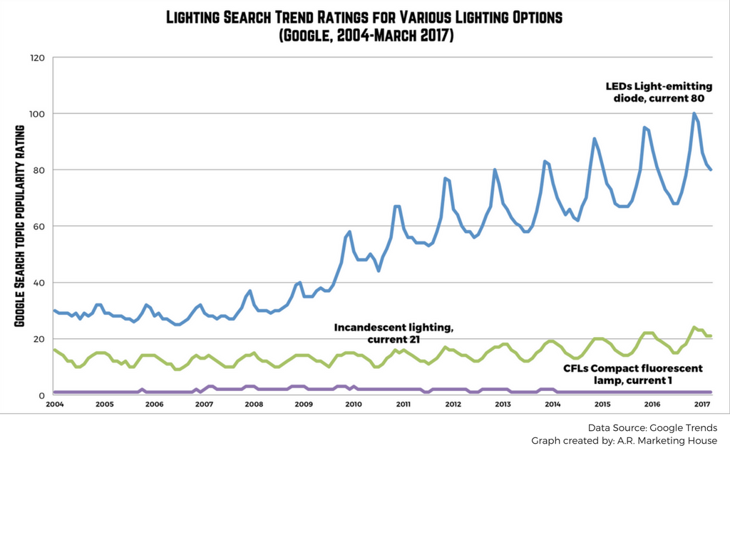
According to Google Trends Ranking, when comparing popular lighting source search trends it is clear that LED is the powerhouse lighting source. The expansive reach and use of LEDs in today’s tech world make it almost unfair to compare it to other lighting sources but we’ve done it anyway.
Below is a graph that displays the overwhelming rise in rank of LEDs since 2004, especially compared to it’s CFL and Incandescent counterparts. Data was collected from Google Search Trends comparison of three lighting sources as a general topic i.e. LED as a general search topic and all related search terms, CFLs as a general search topic with related search terms, and incandescent lighting as a general search topic with related search terms. Click here to see what countries rank highest for the interest in LEDs.
Google Search Trend Rating for 3 Lighting Sources
Full Line SMT Equipment for LED Production
Southern Machinery has over 20 years of experience, carefully designing your customized tailor-made SMT machines to fit your production. Investing in a customized FULL SMT line for your LED manufacturing will improve your quality, productivity, and reliability.
What we provide:
Full LED solutions tailored to your product
Core technology with our equipment
Highly skilled and professional tech service
Deep experience in LED factory setup
All Solutions to your LED Assembly for Quality and best ROI
[su_button url=”mailto: info@smthelp.net” background=”#00a3b3″ size=”5″]Ask Us About LEDs HERE[/su_button]
For a brief time, we will be giving away a FREE Gerber File.
For the first time, Southern Machinery is giving away a FREE Gerber File! If you need help with your design process, we are gladly here to help. Let us make your manufacturing set-up easy and efficient.
We at Southern Machinery know and understand what is needed for a successful PCB Assembly. If you need pharmacy guidance with design, CAD, equipment configuration, training, just ask! Southern Machinery is not just a place to buy machines, but also a place to get your technical questions answered. So ask us! We want to help you find your PCBA solutions.
While in attendance at the 2017 National Association of Music Merchants (NAMM) Show last month we found one thing to be true… THT Equipment is far from dead. The music industry continues to require robust and durable components for high quality and heavy duty gear. GEAR, GEAR, GEAR! And the better the gear the more likely THT was involved in the assembly. Proving that THT is not just surviving but thriving in our high-tech world.
But there are many missing links! Many of these specialty components are still placed by hand and many more are still IMPORTED. Opportunities abound for manufacturers to bring all assembly, quality control, and profits back home. Quality is the name of the game when it comes to being #1 in any product category but costs sometimes hold back some manufacturers. According to Joel Menchey, Menchey Music Service, import costs for audio manufacturers are the highest of all costs. This doesn’t have to be so.
We at Southern Machinery have the solutions to lower costs and improve your manufacturing assembly quality! Our S-600-OF Through-hole & Surface Mounting Multifunction Machine paves the way to incorporate THT with SMT technologies. We can help you design the exact machine for your needs, ordered to spec. It’s a simple conversation for a huge shift in ideology and savings.
[su_button url=”mailto: info@smthelp.net” background=”#00a3b3″ size=”5″]CLICK HERE for more HELP with your THT Equipment![/su_button]
FEATURES:
Six pick-up heads.
Practical placement speed to 18,000 cph.
Huge Component Range: places SMDs from 0402 to 15 mm x 15 mm, including resistors, capacitors, inductors, diodes/
audion , IC, SOTs, SOPs, QFPs and CSPs, and THT components.
Feeder racks can accommodate a mix of tape feeders and IC tube/stick feeders or 5 THT components feeder.
Teaching/fiducial recognition camera for easy programming & operation
Customized nozzles available.
Bottom fixed-camera vision system for fast, accurate alignment.
Ball screw drive and heavy-duty, uni-body construction ensure smooth, high-speed movement and high accuracy and repeatability.
Ensuring the Best Design for Final PCB Production Stage with Testing! Ensuring the Best Design for Final PCB Production Stage with Testing!
Avoiding Design Mistakes with Testing
Improve EMS Productivity by Testing Early
PC Board errors are a drain to EMS productivity. Through analysis and testing PCBs in the pilot stages, a smoother and more educated production set-up can be achieved. By performing automatic impedance measurements and testing of components (chip resistors and capacitors) early on, you can ensure the best design for production.
We recommend applying the best design logics when creating your PCB layout and Test, Test, Test for maximum efficiency and output. According to Circuits Assembly’s December 2016 Magazine, here is the list of 5 Most Common PCB Design Mistakes: “1. The components do not suit the production technology 2. Thermal imbalance 3. Incompatibility between fabrication and assembly technology 4. Component placement at PCB edge 5. Placing fiducials on the PCB’s edge.”
Once you have planned your PC Board with best practices, Southern Machinery’s High-Speed In-line Circuit Board Test Machine will help with testing by incorporating a visual inspection function which allows mounting status checks on each component (e.g.: typo descriptions in alphanumeric characters, orientation, size) on the operator’s monitor will serve to best analyze testing up close. As well as automatically generating test data from mounting data and component list.
Before the manufacturing course begins, business necessities require an in depth verification and comparability of product design vs. manufacturing outcomes, often called First Article Inspection (FAI). Frequently used within the aerospace, medical electronics and automotive industries, FAI studies have gotten an ordinary course of to make sure high quality and consistency of the ultimate product is in order. Although conducting FAI could be advanced, technological developments and person pleasant software programs have allowed customers to implement and execute this course of shortly and precisely.
What is First Article Inspection?
As an official authentication technique for production, FAI intention is to overview and authorize dimensional studies. FAI stories make the most of dimensional properties of a manufacturing like design specs, to make sure of consistency or uncover any deviations. This inspection ensures reliability and repeatability of the manufacturing course, in addition to making certain the producer’s capability to provide elements in accordance with specifications.
What is the aim of FAI?
The goal of a FAI report outlined below:
The FAI report supplies a tenet for goal affirmation that every engineering design and specification is appropriately understood, accounted for, verified and documented.
Ensure the manufacturing course of action is dependable, repeatable and constant
Develops a transparent understanding and communication outlet between purchaser and provider.
Verify the accuracy of drawings, making certain that each adjustments made to any part of the designs are accounted for.
Validate all tooling used for production, guaranteeing the instruments’ capabilities to supply all required elements at defined and accepted speed.
Ensure manufacturing course is succesful and might meets the entiretly of all manufacturing needs.
When is FAI report crucial?
FAI studies are crucial when any of the following occur:
A change in design which may probably have an effect on match, kind or operation
A change in manufacturing supply, course of action, inspection technique, location of producer, tooling or supplies
A change to a special media program that will likely have an effect on match, kind or performance
Production has not been executed for 2 years or more (or as specified by buyer)
FAI Benefits
Before proceeding with manufacturing elements, FAI studies will be helpful in figuring out whether or not a production course of action is able to deliver elements constantly within design parameters. Furthermore, FAI studies present construction between buyer and provider for understanding and verifying the final mission necessities. FAI additionally assists buyer and provider with communications and help to avoid future miscommunication. This course of action additionally ensures that you will be using the precise supplies and instruments, offering an efficient initiative for the anticipated outcomes for manufacturing.
Full FAI vs. Partial FAI
A full FAI requires that each field has been accounted for. With a partial FAI report, any subject missed will affect the FAI sucess. In regards to any excellent fields, they might be crammed out at a later date or utilizing earlier knowledge, on condition that it applies to the precise traits of duplicate elements produced by the identical manufacturing course of action.
FAI Planning
Before the primary manufacturing beings to run elements, many components have to be accounted for with the intention to execute FAI planning, which generally embrace the following:
Records for the manufacturing course of action– manage actions to be executed all through FAI course of and accountable suppliers/organizations.
Ensure authorized materials sources, laboratory and relevant manufacturing, planning, routing and buying are in accordance with the specifications.