Replace the PEC Camera Assembly
If the PEC Camera Assembly is damaged or experiences an electrical or optical failure, the camera must be replaced.
|

|
CAUTION |
| Use caution when handling the PEC Camera and Lighting Assemblies. These assemblies are very sensitive to sudden shock. Also use ESD precautionary measures when handling the PEC Camera and Lighting Assemblies. A properly grounded ESD wrist strap is recommended. |
Prerequisites
Make sure that the following items are available before beginning the procedure:
- A new PEC Camera Assembly
- A calibration kit and a new PEC gray card
Remove the PEC Camera Assembly
To remove the faulty PEC Camera Assembly from the head cage, perform the following procedure:
-
Power down the machine and perform Lockout/Tagout according to local procedures.
|

|
WARNING – LOCKOUT/TAGOUT |
| The machine must be powered down and your site’s Lockout/Tagout procedure executed during this procedure to ensure personal safety. |
- Open the access cover.
- Move the beam to a location where the PEC camera can be easily accessed.
- Disconnect the PEC_VIDEO/PWRPL and PEC_LED_CTRPL cables from the Head Cage Interface PCA.
- Remove all cable ties securing the PEC camera cables to the head cage.
- Remove the PEC camera cables from the cable clamps on the bottom of the head cage.
- Remove the screws that secure the PEC lighting to the PEC camera. Let the lighting hang loose from the hole in the carriage plate.

- Disconnect the PEC lighting cable from the PEC lighting. Set aside the PEC lighting.
- Remove the screws that secure the PEC camera to the carriage plate.
- Lift the PEC camera out of the head cage and discard.

Remove/Install the PEC Camera Assembly
If the PEC Camera Assembly is damaged or experiences an electrical or optical failure, the camera must be replaced.
|

|
CAUTION |
| Use caution when handling the PEC Camera and Lighting Assemblies. These assemblies are very sensitive to sudden shock. Also use ESD precautionary measures when handling the PEC Camera and Lighting Assemblies. A properly grounded ESD wrist strap is recommended. |
Prerequisites
Make sure that the following items are available before beginning the procedure:
- A new PEC Camera Assembly
- A calibration kit and a clean, undamaged PEC gray card
Remove the PEC Camera Assembly
To remove the faulty PEC Camera Assembly from the head cage, perform the following procedure:
-
Power down the machine and perform Lockout/Tagout according to local procedures.
|

|
WARNING – LOCKOUT/TAGOUT |
| The machine must be powered down and your site’s Lockout/Tagout procedure executed during this procedure to ensure personal safety. |
- Open the access cover.
- Move the beam to a location where the PEC camera can be easily accessed.
- Disconnect the camera control/interface cables from the Head Cage Interface PCA.
- Remove all cable ties securing the PEC camera cables to the head cage.
- Remove the PEC camera cables from the cable clamps on the bottom of the head cage.
-
Remove the screws that secure the PEC lighting to the PEC camera. Let the lighting hang loose from the hole in the carriage plate.
(Typical PEC Camera and old-style mount shown below)
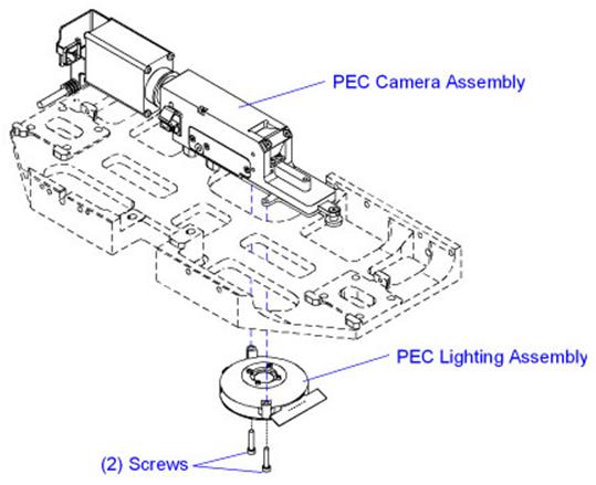
(New-style PEC mount shown below)

- Disconnect the PEC lighting cable from the PEC lighting. Set aside the PEC lighting.
- Remove the screws that secure the PEC camera to the carriage plate or mounting block.
- Carefully remove the PEC from the head cage.
- If installing a camera with a different magnification, remove the 6 frame fiducial inserts on the feeder uprights and the 4 nozzle changer fiducials on the nozzle changer. Retain for use with the .4 MPP PEC camera.
For UPS+ 7.5SC and higher with a .4 MPP PEC camera: Remove the 6 frame fiducial inserts on the feeder uprights; they will not be re-installed.
Install the PEC Camera Assembly
To install the PEC Camera Assembly, perform the following procedure:
- Carefully move the PEC camera into the head cage and position on the alignment pins.
- Apply Loctite 222 to the PEC camera mounting screws.
- Install the PEC camera mounting screws and torque to 1,36 Nm (12.0 in-lb.).
- Connect the PEC lighting cable to the PEC lighting.
- Install the PEC lighting to the new PEC camera and secure with the screws removed earlier.
- Route the PEC cables through the cable clamps on the bottom of the head cage.
- Connect the camera control/interface cables to the Head Cage Interface PCA.
- Install new cable ties to secure the PEC cables to the head cage. Do not over-tighten the cable ties.
- If installing a .4 MPP PEC camera where one did not exist previously, install the 6 frame fiducial inserts on the feeder uprights and the 4 nozzle changer fiducials on the nozzle changer. Install over the existing fiducials.
For UPS+ 7.5SC and higher with a .4 MPP PEC camera: Do not install the 6 frame fiducial inserts on the feeder uprights.
- Close the access cover.
- Power up the machine.
-
Determine if the machine is equipped with the Cognex Vision system:
- Open Diagnostics II.
- Select Version Information > Hardware Options > Vision Systems.
|
If Cognex Vision is…
|
Then…
|
| On the machine |
Continue with the next step. |
| Not on the machine |
Do the following:
- Update the camera drivers. For instructions, see the Update the Camera Drivers help topic in Voyager.
- Continue with the next step after the drivers are updated.
|
- Calibrate the PEC camera and lighting. For instructions, see the PEC Calibration: Camera and Lighting (Multifunction Machines) help topic in Voyager.
PEC Camera Polarizing Components
The PEC camera consists of two elements: a rotating polarizer that covers four of the eight illumination petals and a sliding polarizer. The sliding polarizer is located in the camera aperture. The axis of this polarizer, frequently referred to as the “analyzer”, is orthogonal to that of the rotating polarizer. The combination of these polarizers on the module results in cross-polarized illumination.

(Typical PEC Camera shown)
The rotating polarizer ensures that the substrate is illuminated with linear polarized light. The metal features and ceramic background reflect polarized light differently. The light reflected from the metal has no net change in polarization. Because the orientation of the sliding polarizer located in the camera aperture is orthogonal to that of the rotating polarizer, most of the light reflected from metal features is blocked. Therefore, metal features appear dark on the camera.
In contrast, the ceramic surrounding the metal features randomizes the polarization upon reflection. Because the polarization is randomized, a portion of the reflected light can pass through the central polarizer and reach the camera. Therefore, the ceramic background appears as a shade of gray.
The following table summarizes the polarization effects on metals and ceramics:
|
Material
|
Incident Polarization
|
Reflected Polarization
|
Central Polarizer Orientation
|
Intensity at Camera
|
|
Metal
|

|

|

|

|
|
Ceramic
|

|

|

|

|
Polarized Lighting Zones
The PEC Lighting Assembly has two lighting zones. Which zones are used for imaging depends on the type of substrate being imaged. The two lighting zones are shown in the table below.
|
Lighting Zone
|
LED Color
|
Graphic
|
|
Zone I
|
Blue
|

|
|
Zone II
|
Red
|

|
Petal Zones I and II each contain four illumination petals positioned at 90 degrees to each other. The illustration below shows how the Red (R) and Blue (B) LEDs are oriented.
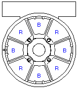
Selectable Polarizer Positions
The PEC Lighting Assembly is equipped with a rotating polarizing filter and high intensity LEDs. The PEC camera has a polarizing film mounted within a rotating ring and a second polarizer mounted on a slide above the lighting module. Certain classes of flexible circuits image well with cross-polarized illumination. For the polarized option, it is recommended that the central polarizer be left in place.
- The blue lighting zone of the PEC Lighting Assembly is designed to image flexible circuits.
- The red lighting zone of the PEC Lighting Assembly is designed to image ceramic circuits.
The following table summarizes the available Polarized lighting options:
|
Lighting Zone
|
Graphic
|
Function
|
|
Zone I
|

|
Orienting the rotating polarizer above the blue LEDs allows non-polarized illumination from the Red LEDs. This lighting type is effective on dark-colored ceramics. |
|
Zone II
|

|
Orienting the rotating polarizer located above the red LEDs allows polarized illumination from the Red LEDs. This lighting type is effective on white or light-colored ceramics. |








 After many requests, we are thrilled to announce our Industry Leader Newsletter. As an Industry Leader, Southern Machinery wants to provide your company with the same excellence we put into our equipment and services. We know your job is important and you must always stay ahead of trends in PCB Assembly. Changes in labor costs, shifting environmental laws and policies, energy conservation efforts, advancing industries, international trade politics, etc., are causing a reemergence of in-house manufacturing systems to be put into place. The tide has shifted and it is now time to begin transitioning to a more self-sufficient manufacturing system.