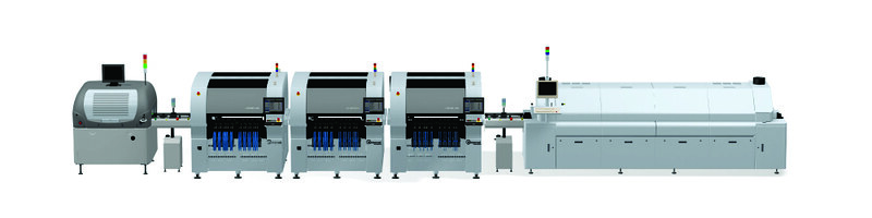
Used whenever the product must be shifted
horizontally or in the Y-axis. Provides multiple
input/output routing paths within the production
line. Can be used to merge lines, combine
or split dual lane applications, distribute
boards to multiple locations, and create
U-shaped lines.
Standard Features
• Configurable length (direction of travel)
• Up to four input/output ports allowing as
many as eight functional routing paths
• Point-to-point pneumatic or programmable
shuttle transfer, depending upon application
• Adjustable cylinder stop for board travel
position on pneumatic transfer
• Allen Bradley PLC
• Independent DC motor drive
• Slide-width adjust
• Fixed front rail
• Adjustable transfer height
• Interface mounting brackets
• Built-in SMEMA compatibility
• CE compliant
Optional Features
• Follow or programmable width adjust
(on programmable shuttles only)
• 4-inch under-machine clearance
Southern Machinery provides professional SMT peripheral equipment

Installation Of The Insertion Head Assembly
To install the insertion head assembly, proceed as follows.
1.Power down the machine and perform Lockout/Tagout according to local procedures.
2.Align the assembly from the back of the insertion head driver assembly and install the pusher onto the bottom of the main shaft.
3.Close the shaft clamp (1).
4.Install the tooling pin (2) and secure it with the set screw (3).
5.Tighten the socket set screw (4).
6.Tighten the hex jam nut (5).
End of procedure
Removal and Disassembly of the Head Drive
Perform the following procedure to disassemble the head drive assembly.
Prerequisites:
Drawing of the Radial Insertion Head Assembly
Electrical Wires Disconnected
Insertion Head Tooling has been removed
Comments:
This procedure assumes that the head drive assembly is being disassembled
to replace the drive mechanism.
To rebuild this assembly, reference the reassembly procedure found in this
module.
If possible, it is more efficient to remove the motors and bearings from the
assembly with the casting secured to the machine.
Procedure:
1.Power down the machine and perform Lockout/Tagout according to
local procedures.
2.Use a clamp to secure the head drive assembly, and remove the 4
mounting bolts. Lift the head drive assembly from the machine.
3.To replace the drive mechanism, first loosen the socket head cap screw
and remove the threaded locking collar clamp from the top of the drive
mechanism shaft. This allows the separation of the bearing assembly
from the top of the drive mechanism.
4.Loosen the screw in the push rod clamp and unscrew the push rod. This
allows the bearing assembly to completely separate from the drive
mechanism.
5.Remove the push rod from the drive mechanism.
6.Remove the ball bushing from the top of the drive mechanism.
7.Loosen the four mounting bolts on the brushless DC motor and push
the motor toward the head assembly, removing the tension from the
timing belt. Remove the belt.
8.Remove the bumper, then remove the theta pulley from the top of the
drive mechanism.
9.Remove the stop ring from the top of the drive mechanism.
10.Loosen the four bolts securing the vertical drive motor and tighten the
1/4 – 20 SHCS jacking screw.
11.Remove the timing belt from the vertical drive pulley on the vertical
drive motor and the bottom of the drive mechanism.
12.Turn the 1/4 – 20 SHCS jacking screw counter clockwise. This releases
the pressure on the compression spring.
13.Remove the vertical pulley from the bottom of the drive mechanism.
14.Remove the grease seal block.
15.Remove the 4 bolts from the bottom of the drive mechanism.
16.Carefully separate the ends of the drive mechanism and remove the
drive mechanism from the casting.
17.Reference the assembly procedures to reassemble this assembly.
End of procedure.
Head Drive Home Pulse Setup Procedure
The following procedure explains how to set up the head drive home pulse
with respect to the vertical and theta axes and the limit position.
Prerequisites:
Timing belts are removed
Tools:
MTR Home Pulse Setup Fixture
Comments:
This procedure is only used when setting the machine up at the factory or
when replacing the timing belt or motor in the field. Timing belts are to be
inspected on an annual basis.
This process is written for the use of both the manufacturing factory (place of
origin) technician performing the adjustment on the bench and the field
technician performing the adjustment at the customer's site.
The goal of this procedure is to position the head vertical at its negative limit
and the head theta at a point between its positive and negative limit
establishing the optima home pulse location, relevant to these limits.
Failure to properly perform this setup results in the machine not zeroing
properly.
Procedure:
1.Power down the machine and perform Lockout/Tagout according to
local procedures.
2.Insert the setup fixture so it positions the head to the negative vertical
limit, and the head theta between its positive and negative limit.
3.Loosen the 4 motor mounting bolts and slide the motor up against the
tension spring. Hold it in position and retighten two of the bolts.
4.Slip the belt off the pulleys. Rotate the head theta motor shaft so that
the mark on the top of the shaft lines up with cables exiting the motor
housing, then rotate the shaft clockwise approximately 20 degrees
further.
5.Attach the belt to the pulleys while holding the motor shaft in
position.
6.Loosen the head theta motor mounting screws to allow the tension
spring to slide the motor into position. Retighten the motor mounting
screws.
7.Loosen the head vertical motor mounting screws and slide the motor up
8.Rotate the head vertical motor shaft so the mark (or keyway, if no mark
exists) on top of the shaft lines up between case mounted connectors of
motor housing.
9.Attach the belt to the pulley while holding the motor shaft in position.
10.Loosen the head vertical motor mounting screws to allow tension
spring to slide the motor into position. Retighten the motor mounting
screws .
11.Remove the setup tool.
End of procedure
Insertion Head Jaw Guide Gap Adjustment
Purpose:
This procedure adjusts the gap between the block containing the jaw guide
and the insertion head housing. When the gap is properly set, the jaw guide
will move freely, but will not be excessively loose. The components can then
be loaded into the head consistently, and the head will not wander during
component insertion. There should be no movement in either a front to back
or side to side motion as illustrated below.
Prerequisite:
Machine powered down and insertion head removed.
Procedure:
1.While holding the head housing, apply front to back pressure to the jaw guide assembly and check for movement between the block and
housing. This movement could be in a front to back direction as illustrated by the black arrows, or in a side to side direction as
illustrated by the gray arrows. Refer to the illustration.
2.While holding the housing, move the jaw guide assembly through its full range of travel to the full up and down positions. Refer to the
illustration. Ensure the jaw guide assembly moves up and down smoothly and rollers D and E rotate without binding.
3.If no adjustment is required, go to Insertion Head Centering Adjustment
procedure. If excess movement or binding exists, or if the rollers do not rotate, continue with the following procedure.
4.To eliminate excessive side to side movement or binding of roller E, loosen set screw F and turn eccentric shaft G in either direction until roller E moves freely. Next, turn eccentric shaft G clockwise until a
slight resistance is felt. Do not adjust beyond this point. Check for smooth movement between up/down positions without excessive side to side movement. Readjust eccentric shaft G as necessary. When
satisfied with adjustment of eccentric shaft G, tighten set screw F.
5.To eliminate excessive front to back movement or binding of roller D, loosen, then finger tighten screws K. Adjust screw J, taking care not to over tighten it, while checking for smooth movement between the up
and down positions and no front to back movement. Readjust screw J as necessary. When satisfied with adjustment of screw J, tighten screws K.
6.Recheck for smooth up/down operation of the guide jaw assembly as well as excessive front to back and side to side movement. If no excess movement or binding exists and both rollers turn smoothly, no further
adjustment is necessary. If movement or binding still exists, repeat above procedures as necessary.
7.Before reinstalling the insertion head on the machine, check the insertion head centering. Refer to the Insertion Head Centering Adjustment section.
End of procedure
Insertion Head Casting Height Adjustment
The insertion head casting height adjustment sets the distance from the
bottom of the plate under the CTA to the top of the rotary table. Failure to
correctly make this adjustment may cause interference between the CTA and
the components on the workboard.
Prerequisites:
Plate has been squared to the upper frame.
Comments:
When attempting to set the head height to the rotary table, do not change the
plate settings. The plate settings are set up at the factory and would require
Procedure:
1.Power down the machine and perform Lockout/Tagout according to local procedures.
2.Loosen the 4 mounting bolts on the head drive casting just enough to allow the casting to slide on the plate.
3.Position the positioning system so that the rotary table support bearing is under the CTA transfer plate.
4.Place the gauge block 34,37 mm (1.353 in.) next to the rear rotary table support bearing (reference point), adjust the setscrew (3/16 allen wrench) until the gauge block slides under and back out from below
the CTA transfer plate with only a slight amount of friction. Check the other side of the CTA transfer plate the same way.
5.After the correct distance has been set, retighten the four head casting bolts.
6.Recheck the setting. If the setting has shifted (become more or less than
it should be), repeat steps 1 through 4. If the setting has not changed,
apply torque seal over the set screw threads.
End of procedure.