Southern Machinery provides professional SMT peripheral equipment


Methods and measures to improve the production efficiency of SMT production line
Abstract
Nowadays, the market competition is more and more intense, how PCB assembly plant in such an environment can to be invincible. The first point is to reduce its production costs. To achieve this goal, the most important way is to improve the production efficiency of the production line. This paper discusses some measures and measures to improve the efficiency of SMT production line based on the author’s work practice.

一. Processing of chip mounting program
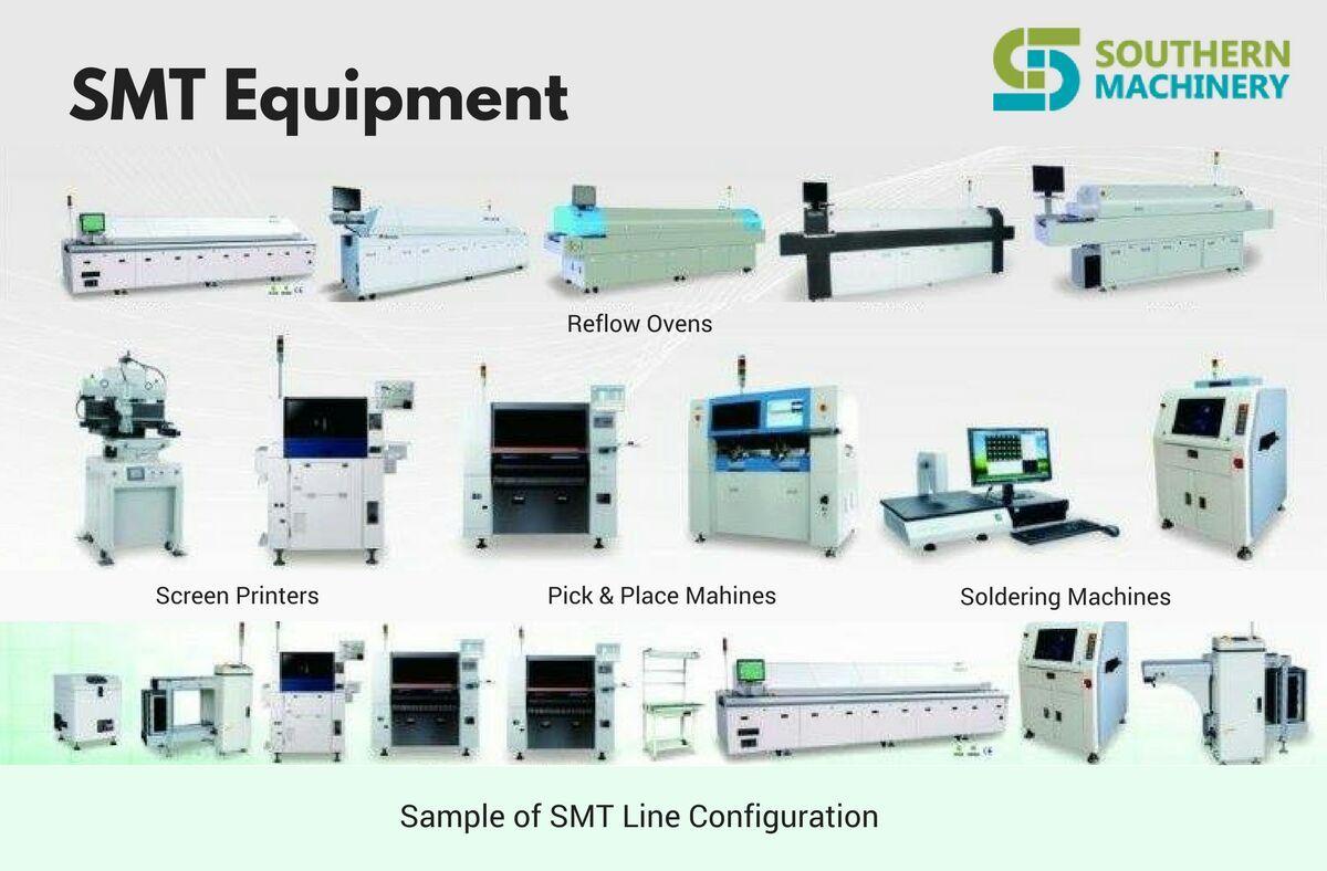
SMT production line consists of a number of equipment, including screen printing machine, chip mounter, reflow soldering and so on, but in fact the speed of the production line is determined by the chip mounter. A SMT production line usually consists of a high-speed machine and a high-precision chip mounter, the former mainly mounting chip components, while the latter mainly mounts IC and Odd-form components. The entire SMT production line has the maximum production capacity when the two patch machine completes an affixed time (hereinafter referred to as the mounting time) and the hourly hour. In order to achieve this goal, we can process the mounting procedure according to the following methods.
- Load distribution balance. Reasonable distribution of the number of mounting components of each device, so as to make the installation time of each device equal. When we first assign the number of mounting components for each equipment, there is a large gap in the mounting time. This requires the adjustment of the production load of all the equipment on the production line according to the mounting time of each equipment, and the part of the equipment on the equipment is moved one part to the other. The balance of current load distribution.
-
Equipment optimization. Each patch machine has a maximum value of the patch speed, for example, the YV100 of YAMAHA is called 0.25 seconds / slice, but in fact the speed value is realized under certain conditions. To optimize the numerical control program for each equipment, it is to make the chip mounter meet these conditions as much as possible in the production process, so as to achieve the highest speed mounting and reduce the installation time of the equipment. The principle of optimization depends on the structure of the equipment. The placement machine for X/Y structure is usually optimized according to the following principles.
- As far as possible, the mounting head can be picked up at the same time.
- When arranging the mounting program, the same type of components are arranged together to reduce the number of changing suction nozzles when the mounting head picks up the components and save mounting time.
- More supplies should be placed near the material station near the PCB.
- During the process of picking up and releasing, try to collect materials only from the front or rear material stations, so as to reduce the moving distance of the head.
- In every cycle of collection and circulation, the head should be loaded.
Notice: Some principles will conflict when optimizing the program, which requires compromise consideration to select the best optimization plan. Optimization software can be used in load distribution and equipment optimization. The optimization software includes equipment optimization program and production line balance software. The optimization procedure of the equipment is mainly to optimize the placement procedure and the configuration of the feeder. After the components BOM and CAD data are obtained, the mount program and the feeder configuration table can be generated. The optimization program will optimize the movement path of the mounting head and the configuration of the feeder, and reduce the moving distance of the mounting head as much as possible, thus saving the time of the mounting. The production line balancing software is an effective tool for the optimization of the whole production line. The optimization software adopts a certain optimization algorithm. The current optimization software has been intellectualized, and the optimization process can be completed faster and better.

二.Eliminating of bottlenecks
The SMT production line is made up of a number of automatic equipment. When a certain equipment is slower than other equipment, the device will be the bottleneck for the speed improvement of the whole SMT production line. According to a sample of 19 factories (Table 1), bottlenecks are often found in chip mounters, and only by adding chip mounters can they be eliminated. Of course, this requires a large amount of capital investment, but it can make full use of the production capacity of other equipment, far more than the investment of a SMT production line. What type of patch machine is added depends on the bottleneck of the production line. In general, it is best to buy a high speed, multi-functional chip mounter machine, because it has the features of both high speed and high precision machines. The range of mounting components covers the high precision machine and the high speed machine. It can solve the problem caused by the high speed machine or the high precision machine. Bottleneck problem. At present, the development trend of chip mounter is also developing in this direction to meet the needs of the market.
| Bottleneck of process steps | Percentage |
| High precision chip mounter | 32 |
| High Speed Chip Mounter | 21 |
| Online testing (ICT) | 16 |
| functional testing | 16 |
| Other | 15 |
| Total | 100 |
Table 1 –Distribution of the most common bottlenecks in a factory
Adding a patch machine to the production line can solve the bottleneck problem and speed up the pace rate. This method provides more production capacity and more feeder position to better balance the production line without significantly increasing the complexity of production line management, which is much more than a single increase in the production capacity of a chip mounter machine. It’s much more powerful.
三.Implementing strict and effective management measures
1.SMT equipment is a precision equipment of mechatronics. Strict and effective management measures are an important way to improve the efficiency of SMT production line. If the components to be supplemented in advance are installed on the standby feeder, the production line will assemble the last few pieces of the batch number in front of the front, and do well the preparation of the next batch of products on the production line and so on.
2.The SMT production line is a large production line, and the output value is calculated in seconds. And the fluency of production and quality of products, besides equipment and environmental factors, human factors play a very important role. For example, if the operator is familiar with the equipment, it will take less time to eliminate problems in the production process, and it will also save production time and improve production efficiency. Therefore, we must attach great importance to the training of employees. In addition to regular professional training, some professional SMT books and periodicals should be used as teaching materials to organize the staff to learn, to cultivate the love of SMT and to improve the comprehensive business level of each person.
3.Regular inspection and maintenance of SMT equipment is also a powerful guarantee to ensure its full effect. Many companies often neglect this because of their heavy production tasks. Once the equipment fails to produce normally, the loss caused by the shutdown is far greater than the cost of regular shutdown inspection and maintenance of the equipment. Therefore, we must emphasize the regular inspection and maintenance of the equipment, so that the equipment is in good condition.

Summary
SMT production needs high investment, but if the management and use is appropriate, and pay attention to several aspects mentioned above by editor , It will fully tap the production potential of the SMT production line, improve production efficiency, in a few years will take back all of the investment, to achieve “high input, high output”.

Wave Soldering Machine User’s Manual S-WS300


Wave Soldering Machine
User’s Manual

Model:
S-WS300
Be sure to carefully read this manual before use * to ensure proper use of the product
Chapter 2 Main Technical Indicators 4
Chapter 3 Wave soldering start-up instructions 5-6
Chapter 4 Interface Operation 7-12
Chapter 5 Installation Adjustment and Commissioning 13
Chapter 6 Inverter Description 18
Chapter 7 Spray Rosin Furnaces 18
Chapter 10 Maintenance and Precautions 25
Chapter 12 General Troubleshooting 27
Chapter 1 Overview
Automatic wave soldering machine is currently the mainstream of electronic products welding process, compared with other manual welding with a variety of manual, has unparalleled advantages, and thus widely used by electronics manufacturers. The automatic claw wave soldering machine produced by our company is the most advanced using modern high-tech technology.
The new design of crystallization:
(1) Unique automated preparation program;
(2) Perfect work/adjustment function;
(3) The temperature is controlled by the temperature control table of WINPARK. The speed is high and the precision is high. It is suitable for long-distance transmission in harsh industrial environments and has high reliability.
(4) The chain speed is controlled by the frequency conversion speed control motor, which is easy to adjust.
(5) Solder joints are of high quality, easy operation and good service. They are reliable products in this industry.
Thank you for your inquiry and use this machine, thank you very much! Before use, please read this manual carefully. It will provide you with all the functions of the machine thoroughly, and it will be fully utilized in production.
Chapter 2 Main Technical indicators
| PCB Size: Max.50~300mm |
| Conveyor height:750±50mm |
| Conveyor speed:0~1.8M?Min |
| Conveyor Angle:3~7º (adjustable) |
| Conveyor direction:L->R |
| Component heigh :Max.100mm |
| Pre-heating zone:600mm |
| Solder pot wave:2 |
| Pre-heating power:3kw |
| Pre-heating zone temp:room temperature–250°C |
| Cooling zone:1 Fan cooling |
| Solder pot power:6kw |
| Solder pot capacity:Approx.200KG |
| Solder pot temperature:room temperature–300°C±1-2? |
| Control method:P.I.D+SSR |
| System Control:PLC + Touch Screen Control |
| Flux capacity:Max5?2L |
| Spray Fluxer:ST-6 Spray |
| Power Supply:3P 380V AC |
| Total Power:max.9kw |
| Normal working power:Approx.1.5kw |
| Air Pressure:4~7KG/CM2 |
| Dimensions:L2460×W1200×H1650MM |
Weight?Approx.600KG
Chapter 3 Wave soldering start-up instructions
3.1 The boot step of wave soldering
a) Confirm that the machine is connected to three-phase ac380v, 5- line power supply and ensure the machine is grounded properly.
b) Open the total air switch and the switch in the electric control box, then open the power switch on the operator panel.
c) The machine Time control switch is lit, at this time presses the manual / The automatic switch icon, the time control switch displays On state, touch screen lit
d) Touch ( enter ) the button until you enter the operating interface, please refer to the instructions.
3.2 time-controlled switch operation instructions

Instructions for use (Time controller is not used for a long time, every three months need to charge once, the charge times <12 hours)
1. first use, or long time after use, when the controller is not displayed, please after the power, with small items in the lower left corner of the hole open.
2. when powered on, the timer is 24-hour system, please hold the “clock” key for 5 seconds, the monitor will display AMin the upper left corner, indicating that it has been the hour system. Press 5 seconds and return to the hour system, at which time AM display is turned off.
(12 hours When AM is the morning, PM means the afternoon)
3. Set switch time: (if the set opening and closing time is the same, the time controller relay suction for a second ) set steps:
| Steps |
Keys |
Set up a project |
| 1 |
Press (SET) (??) |
Enter timed setting (show 1 on) |
| 2 |
Press (Week) (??) |
set every day the same, or week 1-5 the same, week Six Sunday the same, or daily different (if the same daily, you can not press this key, this time does not show the week, while correcting the clock also No need to press this key) |
| 3 |
Press (time) (?)(? ) |
Set Time to open |
| 4 |
Press(SET) (??) |
Enter the timer setting (show 1 off) |
| 5 |
Press (time) (? )(? ) |
Time to set off |
| 6 |
Press |
If the date of the set off is the same as open, you may not press this key |
| 7 |
Repeat 2-6 steps |
Set the 2-8 times switch time |
| 8 |
Press(clock) (??) |
End Time setting |
* If you do not need 8 switch timing, press (clock) key can be into the clock correction.
* If set error or cancel set this press (clear)(??) key, and then restore the original settings once again
* Display without setting (–:–)
4. Clock Correction:
4.1 Press Live (Clock ) and repeatedly press (week ) to the same day. ( if the daily set switch time is the same, can not press this key, direct correction time, points)
|
|
|
MO |
TU |
WE |
TH |
FR |
Sa |
Su |
|
Monday |
Tuesday |
Wednesday |
Thursday |
Friday |
Saturday |
Sunday |
4.2 Press and hold (the clock) and adjust the time by (time) or (minutes).
5. when you have completed the above operation, press The Open/ Auto/ off ” key, be sure to base your current time on the set of self
controls the time switch, causes the monitor the most downlink to display as (on / off ) or at off(auto / off)
| Explicit shows |
Said |
| On at |
Indicates that the timer is in automatic control and in the open state |
| At off |
Indicates that the timer is in automatic control and is off state |
| On |
Indicates that the contact is in a connected state but the timer does not switch on the set switch time |
| Off |
Indicates that the switch time is invalid in the long shutdown state. |
6. check: Press (set) key to check whether the time set is correct.
7. Modify : please press (clear ) The key at the setting , then reset the time and week of the timing switch.
8. End check: Press (clock) to finish checking and setting, display clock.
9. Manual control: Press (ON/off/off) key, can realize random switch
Attention matters
1. Open The setting of time, can not cross set, should be set according to the order of time.
2. Implement timing Switch Control system Time to set the state in the auto , that is, show on / off (on) or from Move / Close ( at off).
3. The use of the environment should be in line with the environmental requirements of the controller, to avoid vibration, shock, corrosion, dust, electrostatic, high-temperature, high-temperature, direct sunlight environment to use.
4. Please store it in the rated voltage and temperature and humidity condition.
5. maximum current refers to the maximum current when resistive load, lamp current = rated current x20%, motor current = rated power Flow x30%, please use in the specified voltage and current range, if exceed the specified capacity, please contact the AC contactor.
Chapter 4 Interface Operation
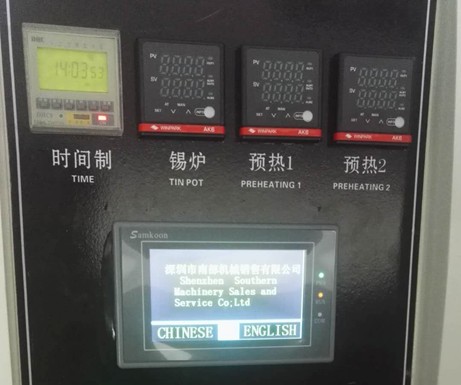 4.1 when the machine electric source button is opened , touch the screen into the Welcome interface ( figure 1 ), waiting about Ten seconds, after the completion of the PLC , the machine automatically open tin furnace heating function.
Figure 1 Startup initial interface
4. 2 Click to touch the screen into the Secretary to introduce the painting surface, such as ( figure 2) Click into the system

Figure 2 Company Introduction
4. 3 Click into the system , touch the screen into the machine to manipulate.the painting surface , as 3.
This painting surface controls all the operation of the machine,
including the manual mode and the self – moving die style.
4.3.1 : Manual mode: Touch screen left upper corner display manual (click to Automatic), manual mode, click Transport, open the chain claw
transport function; Click Preheat, turn on preheat function (must turn on transport to turn on preheating); Preheat temperature to reach, click on the peak, according to the actual product to open the crest, unicast or double wave (long leg wave soldering only a valid), generally only in the back of the red glue patch components need to open the double wave, at this time the peak has been running , the technical personnel can adjust the crest height according to the actual situation; Click on the spray, click the spraying, spray has been working, at this time can adjust the spray size, close to spray, the spray becomes automatic state.
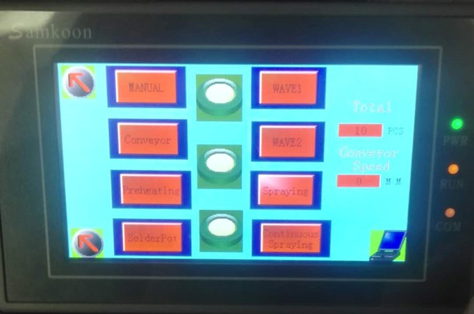
4.3.2 : Automatic mode: Click on the touch screen in the upper left hand corner of the manual switch to Automatic mode, point Open Transport, preheating, as needed to open the crest, spray fog. In the manual mode after adjusting the machine state, at this time the machine can be normal production, when the circuit board into the machine, machine automatic spray, automatic spray, automatic wave soldering.
Fig . 3 machine operator interface
4. 4 Click on the machine in the lower right corner of the EEG map , the machine into the set interface , as shown in Figure four , this screen is used to set the machine‘s shipping parameters.
Spray Distance: This parameter sets the automatic spray time when PCB The board is
transported to the top of the sprinkler start spray, recommended set value to 7 , if PCB
The office has not reached the top of the nozzle has been opened Start Spray, then change
this parameter large, conversely, if PCB after the board is over the nozzle before
beginning to spray, then the parameter is adjusted small;
Spray coefficient: This parameter is not set;
Wave Distance: This parameter is automatic Qipo parameter, when the PCB board is
transported to the front of the tin Furnace, automatic Qipo, this parameter and spray
distance set the same way;PCB board in distance tin furnace 20cm
The peak effect is the best when it is opened.
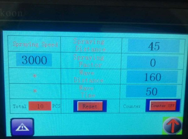 Wave time: This parameter is the peak after the automatic start of the operation time, it is recommended to set the 50-80.
Figure 4 parameter setting screen
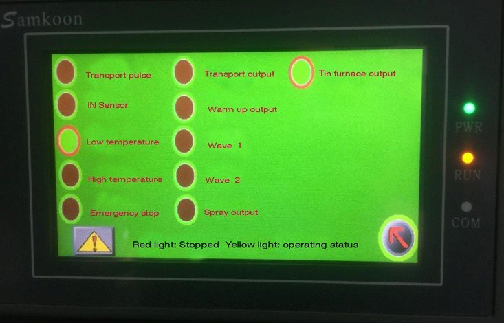 4. 5 Click Control Screen left -pointing arrow chart , into the machine– like monitoring Screen , this screen is used to monitor the operation Status of PLC .
Fig . 5 The status monitor drawing surface
Chapter 5 Installation Adjustment and Commissioning
5.1 Machine Adjustment
After the machine positioning, the level adjustment, first the Foot Cup, so that the rubber wheel off the ground water leveling ruler on the machine to adjust, must make it in a horizontal state.
Adjustment of rail height
(Note: Tin furnace before shaking out, the first tin furnace trolley and rack fixed connection code loosened, and then the tin furnace height lowered, so that the tin furnace nozzle and titanium Claw in the height of a certain gap to avoid damage collision.) The tin furnace can be smoothly shaken out. Note: The foot wave soldering furnace to disconnect the titanium claw first
5.2 Adjustment of Plate feeder
Installation of the machine to install the first access to the plate feeder, the board will be connected with screws fixed, with two
PCB Board to adjust the docking plate, a piece of PCB into the titanium claw inside clamping, a PCB board placed in the plate feeder, two PCB board docking up, By adjusting the plate to the side of the four screw wire To adjust the height of the board connection, so that the two PCB board height parallel, through the adjustment of the machine, such as plate connected to the side of the rice screws to adjust the parallel to the plate feeder and titanium Claw, two fast PCB The joint of the plate butt is completely kissed so that the plate feeder has been installed and adjusted.
Adjustment of 5.2 guideway width
The width of the guide rail can be adjusted according to the different width of the printed board, the printed board Pinto on the Import board, and the printed board side to the fixed edge of the import plate, the rotation width adjustment handwheel to the printed circuit board can be placed on the guide, and can be moderately pushed to the conveyor chain claw mechanism
Attention:
1. Can not hold too tight or loose, too tight will cause the chain claw and plate deformation; Taisong may appear drop board or PCB side stop affect the quality of welding.
2. before adjusting the width of the chain to check whether the two sides of the solder furnace nozzle plate, if you can touch, it is necessary to increase the guide or reduce the tin furnace, so that the chain claw higher than tin furnace spout Guide.
5.2 Adjustment of Tin Furnace
The height adjustment of the tin furnace can be completed by the tin Furnace trolley lift, and the height standard is approximately 6mm~8mmfrom the top edge of the nozzle by the base board component foot.
5.3 Conditioning of preheating box
The position of the preheating box is fixed before leaving the factory, and can not be easily changed, the preheating box should ensure the bottom
The temperature of the face is between the 80?-180?.
5.4 adjustment of flux spray height
The spray height adjustment is done by adjusting the nozzle height and adjusting the appropriate air pressure and gas.
Loosen the screw that the nozzle is connected with the shaft, the nozzle can be moved up and down, and appropriate adjustments can be made according to the actual needs.
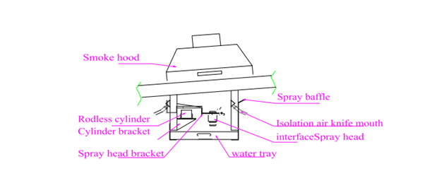
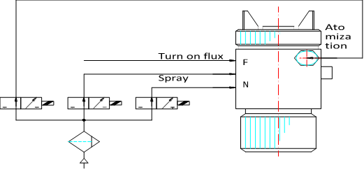 5.5 Nozzle Air Connection mode
5.6 adjustment of the flow of wash claw liquid
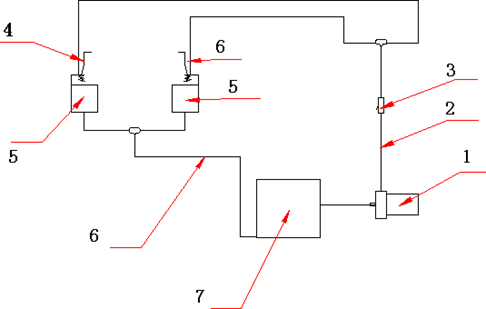 * The adjustment of the volume of wash claw liquid. (see chart below)
|
1.-Alcohol Pump |
2.-Output Pipeline | 3.-Control Valve |
4.- Chain Claw |
|
5.-Wash Claw |
6.-Reflux Pipeline | 7.-Alcohol Box |
The claw pump has a switch control in the touch screen and requires alcohol in the alcohol box and turns on the drive Chain to open
Claw Washer is to ensure that the chain claw clean, to achieve solder quality one of the factors. The device uses a loop-back -flow design, the chain claw through the alcohol moist brush cleaning, flow through the control valve. The capacity of the alcohol box should be Paute 2/3 or more, otherwise the pump will burn, every two days will wash the claw box out of the tin slag clean.
Note: Do not turn the adjustment switch too large and the alcohol overflow machine, so as not to cause a fire.
5.7 Commissioning
after the equipment is installed, the equipment should be fully checked, and after the system and mechanism are working normally, then put into normal use.
* Prepare Equipment
flux approx . 20L
Cleaning Lotion about 12L
Solder lead -free solder 400kg
Electric Stove 3Kw 1
Stainless steel tank 1
* Molten Tin
The solid solder is poured into the stainless steel container in batches, heated to the furnace to fully melt ( about the? ), and then poured into the tin tank of the equipment, when the solder liquid surface is about 8mm from the tin Groove mouth , Stop feeding start-up equipment, the tin furnace temperature preset for 245?, to tin furnace temperature, start the crest, adjust the crest height, check whether the crest is normal. Josi surface is low, at this time can be the bar-shaped solder directly into the tin furnace, adjust the tin surface to fit. Note:a. Tin Tank for the first time, the Solid Tin Bar ( block ) material directly into the tin furnace to melt, In case a large amount of heat can not be passed to the solid solder in time, resulting in high-temperature burning tin trough and heating pipe. b. Before dissolving the tin, the tin trough and the stainless steel container should be cleaned to prevent the impurity from polluting the solder.
* Check Flux Spray Condition
The flux is injected into the rosin groove, connected to the gas source and activated. “Spray Fog ” , check whether the spray is normal. the proportion of flux in accordance with the requirements of manufacturers and actual use of the situation, can be 0.80~0.87 within the scope of appropriate adjustments. ( manufacturers are best to provide free cleaning flux)
* Other
Check the transmission, adjust the body is normal, respectively, start the transport, washing claws, cooling, preheating and so on, check is normal, commissioning completed.
Chapter 6 Inverter Description
(See VFD-M Manual and temperature control sheet , This manual is presented in conjunction with the instructions )
Chapter 7 Spray Type Rosin Furnace
7.1 composition of rosin furnace
Rosin furnace is made of stainless steel, sealed containers, flux stored in this will not evaporate and absorb moisture in the air, and maintain a stable solvent composition, and with high-precision import nozzle and Germany or the United States rod-free cylinder, imported light eye, is currently the most ideal welding equipment users. The structure is shown in the figure below.

7.2 correct use of rosin furnace
the height of the rosin spray can be adjusted (see spray height adjustment), can also adjust the solenoid valve on the airflow regulator or pressure regulator on the air conditioner, the factory has been adjusted so easy to change, to avoid making into the spray system chaos, when working when the substrate through the input photoelectric tube, time control system started, and began to delay spraying and spraying tin until the substrate through the rosin furnace 3-5 seconds to stop spraying.
Note: The flux must be clean-free dapoxetine type, which is characterized by the plate surface after welding without ultrasonic cleaning, clean and beautiful board.
7.3 instructions for the use of nozzles
I, the safe operation of the case of special attention to the following matters:
7.3.1. Take appropriate precautions before use to prevent injury to the human body or damage to the product.
7.3.2. Do not point an open flame or close to an open fire place, to avoid static electricity.
7.3.3. In the installation or maintenance process should be all fittings with raw tape, such as the connection slack, in the gas
Under the pressure of the body, various liquids will be sprayed into the body.
7.3.4. When connecting the air pipe and the solvent pipe, please select different material and pay attention to the pressure of the hose can not exceed the regulation, do not use the damaged old trachea.
7.3.5. Often clean the nozzle on the solvent, the residue on the road, may cause trouble, is in the direction of people can not press the switch.
II. Methods of Use
1. Install despotism M10 stainless steel screws tighten.
2. When installing trachea and solvent fittings, please seal with raw tape, no leakage.
3 . The standard jet pressure is 0. – MPa, standard distance 200-0 mm.
4. Adjust the valve nut ( vent quantity ).
5 . on the nozzle labeled ” F “Then solvent Pipe interface,”N” “C” to connect the air pipe. “N” is a jet input pipe interface.
III. Maintenance and Repair
1. After each class work completes promptly cleans the nozzle the superfluous residue agent.
2 . use a brush or toothbrush when cleaning. (be careful not to damage the gas cap and nozzle “O” rings.)
3. Periodically add grease to the “O” ring to add lubricating oil to the needle clamp. Take care not to tap the needle when removing the clip.
Fault Handling table
| Symptoms |
Possible causes |
Handling countermeasures |
Solvent Breakpoint
1. Insufficient amount of solvent
2. Liquid tube Hardening is blocked
3. Nozzle slack or damaged
4. Needle Clamp Fixed nut loose
1. Supplemental solvents
2. Replacement of liquid Tube
3. Tighten or replace
4. Tighten or replace the needle clip
Side Type Spray shape
1. blockage or damage of valve vent empty silo
2. The nozzle has a dirty glue
1. Clean or replace
2. Clean or replace
The spray shape is Crescent type
1. Valve vent empty bin obstruction or damage to the internal wall of the valve adhesion solvent slag valve center hole damage
2. The nozzle has the dirty material adhesion or the nozzle damage
Cleaning or replacement
The spray shape is thick type
1. Valve Center hole too large
2. Low Injection pressure
3. High solvent concentration and high pressure
1. Replacement
2. To adjust the high bias pressure
3. Diluted solvents ,Reduce driving pressure
The spray shape is narrow
1. air pressure is too high
2. slag between valve and nozzle
3 Reduce air pressure
4 Cleaning
7.4 Daily maintenance and precautions
7.4.1. after Regular cleaning nozzle to ensure smooth nozzle.
7.4.2. always keep the liner slide clean and lubricated, no solvent immersion, so as not to affect the rod the normal use of cylinders.
Chapter 8 Preheater
8.1 the role of Preheater
The role of preheater is to increase the expansion rate on solder pads by preheating the flux activation and
To promote the evaporation of the PCB flux solvent, thus obtaining the best soldering effect. In addition, the circuit board after preheating, reduce the PCB and tin furnace temperature difference, to avoid the thermal impact of electronic components and circuit board sudden thermal deformation.
the optimum temperature for preheating is 120~180?. The temperature is too high can cause undesirable consequences; too low temperature affects welding quality.
8.2 The construction of preheating box
the preheating system is composed of imported blackbody heating pipe. The Preheating box and the guide rail are connected by screws to facilitate the inspection and maintenance of the line.
The best preheating temperature on the circuit board is 120-180 ?, the temperature of the preheating box is passed by the high accuracy temperature probe to the preheating electronic thermostat to adjust, can accurately control the preheating box temperature, protect the circuit board, achieve the most ideal preheating effect.
8.3 Daily Maintenance and Precautions
8.3.1 The temperature of the circuit board’s bottom surface is often tested to ensure that 120~180? between the two to ensure the best solder effect.
8.3.2. Check whether the circuit wire aging, in order to prevent current interruption.
8.3.3. Clear the flux residue in the drawer of preheating box, lest the set will cause fire.
Chapter 9 Tin Furnace
Tin furnace structure using stainless steel production. By the wave generator, nozzle filter, impeller, motor and other groups
Yes. The use of pump-type principle to form a crest.
Tin furnace structure is reasonable, high technical content, the use of Japanese and American tin Furnace advantages of the development of high standard tin furnace. Its characteristics:
1 reduce the tin oxidation to a minimum.
2 nozzle wave smooth, tin surface can be adjusted vertically to adapt to different PCB board welding requirements,
3) External heating effectively avoids the phenomenon of explosion tin, good insulation performance, tin furnace durability does not deform.
4) long service life.
Tin furnace body is by corrosion-resistant stainless steel plate welding into, heating tube installed in the tin furnace two outside. Use
Alloy
Plate to radiate heat, so that the temperature uniformity of the tin furnace, the overall heat balance does not deform, spray cavity set up without clogging nets,
Can keep the peak smooth and smooth, and not plug, thus reducing maintenance, improve efficiency.
9.2 correct use of tin furnace
Tin Furnace high and low and in and out of the mobile can be used to set up the joint hand wheel and lifting screw adjustment , adjust the tin Furnace crest can be adjusted by the frequency converter, the higher the impeller speed, tin furnace crest is higher;
Solder temperature controlled by the thermocouple in the tin Furnace. First of all, the expected solder temperature set, usually the normal solder temperature is 230-250 ?.
In the back of the tin furnace with a row of tin Tsui, used to clear the tin furnace. The tin furnace to the back of the removal, cleaning and maintenance, before the tin furnace removed, must first be the guide rail high or tin furnace to reduce a certain height to avoid the rail chain claw and tin furnace collision caused by the chain claw deformation.
In the demolition of the furnace, referring to the structure shown above, the nozzle removed first, the motor frame and impeller out, loosen the furnace liner fastening bolts, you can remove the furnace.
9.3 Daily maintenance and precautions
9.3.1. Regularly check the amount of tin to control the “spray tin wave.”
9.3.2 . measure soldering temperature with mercury thermometer ( standard temperature0?). If the preset solder temperature is unstable , it can be adjusted in the temperature control table.
9.3.3. Depending on the resulting oxide, add antioxidant grease. (Anti-oxidation grease and flux supporting use)
9.3.4. Frequently remove oxides from tin furnaces.
9.3.5. Check the tin furnace motor coupling on the machine rice and impeller shaft coupling machine meter and its operation, to ensure its normal operation.
9.3.6. Pay attention to check the wire has no aging, as well as the parts of the screws, nuts are loose.
9.3.7. Spray nozzle every day after work with alcohol automatic cleaning, lest block.
Chapter 10 Maintenance and precautions
1. Often the fuselage, transport, claw pump, cooling fan, such as motor housing cleaning to facilitate the cooling and insulation.
2. Regular inspection of electrical control box in the electrical appliances and fastening the screws on its terminals, such as the discovery of contact ablation, suction and not flexible, etc., should be dealt with in a timely manner.
3. Regular inspection of preheater, tin furnace heating pipe joints, such as the discovery of head loosening, poor contact, insulation aging and other phenomena should be tightened, clean and replace.
4. Regular inspection of equipment to protect the grounding device is good.
5. In the operation of the equipment, pay attention to monitor the shell temperature of each motor, overheating phenomenon should be stopped check.
6. When the general switch on the power supply, should first stop the tin Furnace, preheating and wave crest and other large current load before entering
Yes.
7. After the main power switch trip, you must find out the cause of the failure, before the closing.
8. In the process of melting solder and injecting high temperature liquid solder into the welding furnace, wear protective articles to prevent
Scald.
9. Flux, Wash claw liquid are flammable materials, use should pay attention to fire safety.
Ten after working every day, you need to clear the flux residues in the preheater to prevent accumulation. cause an open flame.
11. The limiter can not be added lubricating oil, so as to avoid the transmission chain claw not go.
12. Anti-oxidation wax (oil) should be used with flux to avoid fire.
13. Each transmission part should maintain the good lubrication, except the angle adjustment mechanism may use the ordinary ointment, other all uses the High-temperature ointment lubrication.
14. The tightness of each transmission chain should be checked and adjusted regularly.
15. Regular inspection of tin furnace speed motor lubrication and operation, to ensure its normal operation.
– Tin furnace Nozzle should be based on the peak stability, the peak when the exception to clean the nozzle, so as not to affect welding quality.
18. Spray nozzle should always check the tightness of its connection.
Chapter 11 Wiring
This equipment needs external 3? , ac380v,50HZ power supply ( three-phase five wire system ), power supply capacity
The quantity is not less than 20KVA, the equipment shell should protect the grounding, the grounding resistance ?4?, the grounding conductor is not less than
4mm2, the incoming line should be no less than 6mm2?
Chapter 12 General Trouble shooting
To ensure high quality, the devices used in the equipment are advanced industrial countries of high-quality products, such as million
In the event of an accident, please check each of the items listed in one table. If you are still unable to resolve, please contact the company directly.
| Failure phenomenon |
Reason |
Check processing |
All action buttons are invalid
1. Time is not in the state of timing
2. The tin temperature is not up to the set value
1. Set the scheduled boot time before the current time.
2. Wait until the temperature of the tin furnace, then operation.
Control power LED not lit
1. Power supply Missing phase
2. Fuse on the bottom plate of the electric vessel
1. Overhaul power supply.
2. Check whether there is a short-circuit phenomenon in the lights, etc.
In addition to the failure, replace the new insurance pipe (4A).
Power supply Total Switch tripping
1. Load and line occurrence short-circuit phenomenon
2. Power supply Total Switch Contact bad
1. Check the load and related lines, troubleshooting short-circuit.
2 . Check the wiring area of the power supply master switch for appearance loosening, heating, oxidation and whether the switch contact point is out contact is bad, ablation and other phenomena, or to be seized
repaired or replaced.
Tin Furnace or preheating
Slow warming of the device
1. Power supply is too low
2. Additional Hotline ( tube )partially damaged
1. Improve the quality of power supply.
2. Replace the hotline ( tube ) .
Transport Claw not running
1. Transport motor shaft end of the drive chain skid, Force nut Loose
2. chain speed set to “0”
3.fx-2da or inverter damage
1. Fixed nut for fastening drive sprocket.
2. chain speed set to not “0” position.
3. fx-2da or inverter.
Failure and solder welding problem analysis
| Fault |
Possible causes |
Press the button to press , But the LEDs are not lit
1. Total switch not open, emergency stop switch not open
2. LED light bulb failed
3. Total switch failure
Press the button to press, but the machine does not run
1. Total Switch not open
2. Press-twist failure
3. Relay failure
When the Rosin furnace is bad
1. The pressure of the rosin furnace is too low
Uneven Rosin Coating
1. The nozzle is damaged
2 . Water, obstruction of trachea
3 . The density of the rosin liquid is too dense
4. Air pressure is too low
5. Pressure regulator failure
Preheater temperature too high and too low or preheater
1. Voltage is too high or too low
Bad use
2. Heating line burnt or terminal loose.
3. Temperature probe Abnormal
4. Temperature control Failure
Tin furnace can not maintain enough tin crest
1 . The nozzle has been blocked
2 . Coupling loosening
3. Impeller Wear
4. Motor Transport Instability
5. Tin solder is impure, especially when the zinc content is larger than the specified value
6. The furnace temperature is too high
Welding problems and Treatment methods
|
Solder state after soldering |
Original for |
Branch Square Law |
Welding is not good
1. Surface oxidation of copper foil pollution
2. Flux preheating is not enough
3. Too little Flux
4. Low solder temperature
5. Conveyor belt speed
6. PCB in the tin solution leaching excessive
7. Copper foil area is too wide
8. Wuxi Protective Film
9. Flux and molten solder do not melt
Clean copper foil and component ends; PCB, components for long-term storage, research flux is no problem, for new flux.
Out of the tin pillar
1. Copper foil surface, component ends of oxidation and pollution
2. Solder welding of flux is not good
3 . The chemical changes of the coating flux and copper foil 4. Flux metamorphism
Clean copper foil surface, fully preheat, Preheat temperature standard: Aldehyde circuit board to
– ?, epoxy circuit board 120 to?
(Solder surface temperatureadjustment flux, eutectic solder , temperature for250~260? circuit board and tin liquid contact do not exceed the road plate thickness of the 1/2. Reduce the height of the tin liquid to adjust the speed of transmission , research circuit board design, in
Circuit board coating Protective film.
The occurrence of the lap
1. Copper foil surface, component ends of the oxidation of pollution
2. PCB Solder direction is not good
3. PCB design is not good
4. No Solder protection film
Cleaning the copper foil and the side of the side of the oxidation of dirt, change the direction of the circuit board solder, coating Tin protective film, the study of circuit board set
Millions
No tin on the ends
1. Oxidation of the dirt on the ends
2. There are things that do not touch tin (e.g. paint, organic resin)
3. Solder welding of flux is good
4. Flux time too long quality deterioration
Clean copper foil and the end of the surface, do not hang tin, with the pump to remove the attached oxide, dip welding do not exceed the thickness of the PCB 1/2
Virtual Welding Baken Bubble
1. Solder temperature is too low
2. Solder welding of flux is not good (low ratio of flux)
3. Oxidation of the dirt on the ends
4. Surface oxidation of copper foil pollution
5. Flux deterioration
6. Conveyor belt speed too fast
7. Wuxi Welding Protective Film
8. The circuit board damp produces the bubble
solder welding temperature is defined as 250~260? Inspection Welding Agent to remove the ends of the oxide adjustment parts of the ends line Diameters (D) and Aperture d ( e.g.
d=1.d=0.8 conveyor belt speed of one meter per minute, the circuit board in advance drying.
Some places do not touch tin
1. A part of copper foil surface pollution
2. Sipo and PCB contact but do not hang tin
3. PCB Bending
Clean the ends of the line (stripping or welding again) to avoid long-term storage, check the flux or change the new
Flux.
PCB Bending
1. Solder temperature is too high, preheating temperature
2. Conveyor belt speed is too slow
3. PCB does not press well
Solder Solder temperature is 250~260?, transfer with speed set to standard one metre per minute, line
The corners of the road plate are pressed tightly.
Chapter 13 Appendix
Appendix I: Selection of welding process parameters
The selection of welding process parameters has been described in the relevant chapters for easy access to the present list as follows:
| Choose |
Process parameters |
Select Range |
Notes |
| 1. |
Tin Furnace Temperature |
230~260? |
245 ? is generally optional |
| 2. |
Preheating temperature |
80~180? |
PCB welded surface after preheating should reach the single panel 90 ?, double-sided Board 110 ? |
| 3. |
Transport speed |
0~1.9m/min |
Generally optional for 1.2 m/min |
|
4. |
Flux proportion |
0.80~0.87 |
According to the technical requirements of the flux manufacturer and the actual welding situation Adjustment |
| 5. |
Crest Height |
Press at 1/2~2/3s |
Thickness of s= printed circuit board |
Appendix II: Technical parameters of lead-free solder
Name |
Alloy Composition (wt%) |
Melting temperature (?) Solid state line/liquid Line |
|
| M – Series Solid state temperature 200~250? | |||
| M31 |
Sn-3.5ag-0.75cu |
217 |
219 |
| SA2515 |
Sn-2.5ag-1.0bi-0.5cu |
214 |
221 |
| M41 |
Sn-2.0ag-0.5cu-2.0bi |
211 |
221 |
| M42 |
Sn-2.0ag-0.75cu-3.0bi |
207 |
218 |
| M702 |
Sn-3.0ag-0.7cu |
217 |
219 |
| M704 |
Sn-3.35ag-0.7cu-0.3sb |
218 |
220 |
| M705 |
Sn-3.0ag-0.5cu |
217 |
220 |
How to design SMT factory layout for Smart EMS
How SMT workshop planning? It turned out to be so useful.
How SMT workshop planning!
And only after the plant began production found that some areas have not planned beforehand, need to be adjusted, resulting in a waste of human and financial resources and valuable production time.
Therefore, it is important to check in advance SMT factory layout, especially for new SMT factory business, because there is no experience in SMT plant layout, the need to pay attention to the elements is not very clear, if we find a problem in the layout after production point, will cause some unnecessary losses.
So, when doing layout SMT plant, what to pay attention to what matters in advance to do to prepare? Here actual cases where we work to and we explore this problem.
Case
planning SMT line configure
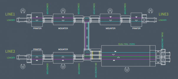
the client recent planning new on two identical SMT production line, specific device configuration (see FIG. 1) and the size of the apparatus is as follows: According to Figure 1 can be seen, the maximum width of the production line equipment is 1.71 m, the length of all devices sum is 13.6 meters, will add future planning a production line (line bulk on equipment configuration).
Situation Workshop
Workshop length 36 m, width of 12 m, an area of 432 m2, on the ground floor of the factory. Currently common ground for the shop floor, and no established anti-static system, can not meet the requirements of SMT antistatic workshop, but two conductive ground terminals, can establish subsequent workshops antistatic SMT system. Further, there is no air conditioning workshop and humidifiers, can not meet the requirements of SMT workshop temperature and humidity control. There workshop ventilation system, back to meet the requirements of the reflow furnace equipment. Workshop sufficient power to meet the electricity needs of all equipment in the workshop. There are two entrances whole plant, as are required to meet the equipment, raw materials and semi-finished channel. Special materials warehouse in another workshop, the need for planning. Good lighting conditions in the workshop, to meet the brightness of the SMT shop lighting requirements all stations. Whole plant layout situation shown in Figure 2.
Customer requirements
1, the current new move into production lines and related aids, regional positioning;
2, the whole plant to meet future erection and production requirements three production lines, without planning zone realignment;
3, each production line starting position as consistent as possible, so that the whole plant orderly arranged in three lines.
Subject of
analysisthe customer’s request, we first analyzed how the production line positioning; and before locating the production line, we consider the following points:
1, SMT equipment should avoid column and they maintain a certain distance, the distance is equipment installed at least after a good feed material by a vehicle;
2, SMT crossing equipment required for frame division pitch, and the crossing equipment to extend outwardly after the device installed above the material 50 cm;
3, optimal spacing of the two lines spaced more than 1.2 meters between the outer frame;
4, check the wire tail is generally a repair plan area, quality control personnel can perform sampling line tail region.
Based on the above considerations, the length of each line should be at least 13.6 meters (without regard to the maintenance area and the tail, the case where the sampling area and the thread area kanban), the width should be 2.7 meters (SMT feeding both surfaces), specifically as shown in Figure 3.
Therefore, the production line is positioned in substantially considering plant shown in FIG. 4.
Some details of the requirements of SMT plant layout
after determining the approximate location of the production line, when the need to consider some details of SMT production line requirements, and then to determine the exact location and the location of other auxiliary equipment SMT line.
First, we analyzed the SMT line position and aids required for each area requirements: 1, fire extinguisher drop zone;
fire extinguishers to be placed around the side of the post and SMT plant, placed according to the requirements of fire regulations.
2, the car rack placement region; car rack replacement for SMT production line models and switching material, in order to facilitate production and to improve the efficiency of replacement materials, preferably the vehicle is placed near the rack placement machine.
3, stock units rest area;
stock table mainly used in the production process and dryer materials stock preparation before switching, therefore, to be placed near the preparation station placement machine, and the best car rack together, Preparation facilitates directly on the car frame after a good feed material.
4, the shelf rest area printing station;
printing station for positioning the shelf aids in the production of printing presses, such as wipes, paste, alcohol, etc., to be placed in the vicinity of the printing press to facilitate removal use, improve Productivity.
5, placing solder paste regions;
region comprising placing solder paste storage refrigerator, solder paste mixer, paste warmed cabinets, can be placed next to the plant as required or uprights placed around a fixed area of the plant, However, to facilitate the operator to take place.
6, visual inspection after the furnace area, maintenance area;
in order to facilitate visual inspection after reflow and rework semifinished product, a shelf generally placed in the furnace, designed for the visual inspection of the furnace and rework.
7, screen placement area;
drop zone comprises a mesh screen plate was placed cabinet, stencil cleaning machine, inspection tools, screen, stencil for storing, cleaning and inspection screen tension, etc., while in the region as much as possible to facilitate the production screen to take place.
8, garbage drop zone;
Production waste mainly from two parts, wipes and the like used in one printing operation, the second is to replace the waste tray and waste material produced with the like. Garbage two parts is generated to be placed separately, specialized recycling, in particular waste presses used. Thus, waste area may be placed next to the press machine or patch, or set beside the column region refuse placed separately placed.
9, kanban placement region;
kanban including the SMT billboards and other signage quality management, may be centrally located on the entrance into the shop, and also set up the production line Kanban state in which each head of the line, in order to view the producers and managers, promptly understand the current state of production status and quality SMT workshop and so on.
10, product placement area;
include products produced finished products in two parts, to separate the two partial regions divided out, strictly distinguished, in order to avoid confusion.
11, SMT placement of spare areas;
Nozzle including the SMT spare parts, a motor, a belt, cylinder or the like, to be placed in a special area, to facilitate the production of access.
12, location area temperature and humidity;
temperature and humidity conditions in order to better understand the SMT plant, depending on the size of the workshop area, several appropriately set the temperature and humidity measurement area, generally placed on the production line next to the column or wall.
13, SMT workshop office area;
let engineers and technicians and management personnel in office SMT shop floor, which can solve the problem on technology and management encountered in the production, to ensure the smooth operation of the SMT production lines.
14, anti-static protection area;
entry into SMT workshop area must have good anti-static measures. You may delineate the area in front of the plant, including the replacement of static clothing, shoes, hats and so on each employee’s locker. Also, the establishment of regional designed to test the static ring in SMT workshop at the entrance, so that each employee to do static loop testing and record test results before going to work. Based on the above analysis, the results of this SMT plant layout is shown in Figure 5.
In addition, SMT workshop also meet other requirements: 1, anti-static processing;
shop floor must be anti-static treatment, a common anti-static conductive flooring and paint and other ordinary places, customers can choose according to the actual situation. In addition, anti-static system must be set up in the workshop, to meet the requirements of the entire anti-static SMT workshop.
2, air-conditioning and a humidifier; SMT workshop to meet the requirements of temperature and humidity control.
3, the material management requirements;
in the warehouse, with particular attention to the way the material is stored, reel packaging methods, the use of hook-type place, wetting elements employed Cabinets for placement shelves to be treated with anti-static manner.
4, patch equipment gas and electrical circuitry;
preferably introduced directly from the production line at the down side of the roof, is arranged below the gas passage in the device and circuit wrapped with wire groove.
5, the ventilation system requirements;
needs to be installed to meet the requirements of the three power lines of the blower, and the third exhaust port reserved line.
Results
1, according to the size of production line and the size of the entire plant SMT, completed the reasonable position of the production line; and
2, for aids, regions, etc. SMT production lines need to make the corresponding position location; 3, according to the SMT the characteristics of the plant, some of the necessary factors to consider in planning, in particular, anti-static; 4, in accordance with the requirements of the current situation and future development of the factory has been take into consideration, unified planning.
Summary
For SMT plant layout, but also requires a combination of size and product requirements and other plants to consider a number of factors, but to stimulate here.
Welcome inquiry
1,Please visit : www.smthelp.com
2, Find us more: https://www.facebook.com/autoinsertion
3, Know more our team: https://cn.linkedin.com/in/smtsupplier
4, Welcome to our factory in Shenzhen China
5, See more machine working video, please Youtube: Auto Insertion
6, Google: Auto+insertion, to get more informations
7,Looking forward to your email: info@smthelp.com
https://docs.google.com/document/d/e/2PACX-1vSFUaow2vtLCQbtVShngWxA2uiLkcv6i4BKn4ORhsatobh8Ah_ONk2bFfjkAOSsZf3yKfBrj2hULMi0/pub

Use of PCB Pallets in Wave Soldering
Use of PCB Pallets in Wave Soldering
Patch components are used more and more on the circuit board, but there are still some perforated components between them. For this kind of board, selective soldering is the best solution, but not every company has enough funds to purchase selective soldering equipment, or the number of this type of circuit board is too small, specifically to buy selective soldering equipment is not Cost-effective. Manual welding is prohibited in certain industries such as the automotive industry

Therefore, in PCB wave soldering, using trays to block those patch components is a good method: reliable, fast production, and adaptability to high-capacity requirements.
www.smthelp.com

The benefits of using trays:
Lead-free soldering requires higher soldering temperatures. Therefore, the circuit board is more easily bent during welding. The tray provides maximum protection of the circuit board during soldering and prevents bending.
Similarly, in the automotive and consumer electronics industries, many special-shaped circuit boards have emerged for the needs of applications. It is sometimes difficult to transport these shaped plates with conventional chain rails and mesh belts, and placing the circuit board plates in trays allows any type of circuit board to be shipped.

By soldering some of the bottom components through the tray, it is also possible to use PCB wave soldering equipment for selective soldering of the product.
Since most trays are thick (sometimes 15 mm), solder certainly does not flow to the top of the board. The oxide layer on the solder surface will also be washed away by the edge of the tray before the board reaches the peak, so that when the solder starts, the tin is relatively clean.
By adding some stiffening strips to the tray, it can increase its hardness to withstand high-strength welding. It is also possible to install heat-absorbing blocks, component fixing devices and some other auxiliary devices on the upper part.
The use of pallets also helps standardize the width of the product line, soldering different circuit boards on the same production line, and can use bar code readers and other identification tools to quickly change process programs for different boards.
Although there are many advantages to using trays in lead-free soldering, it can also cause solder balls.
Requirements for pallet materials:
In order to maximize the service life of the trays, the trays must be made of materials that can withstand high temperatures and harsh process conditions, especially for lead-free soldering.
www.smthelp.com

To meet these requirements, the material used to make the tray must meet the following characteristics:
• High dimensional stability
• Good thermal shock resistance
• Can remain flat after repeated use
• Corrosion resistance (flux and cleaning agent)
• Does not absorb moisture
The use of the tray brings the process problems:
The flux system must be able to spray the circuit board completely with flux. Poor tray designs can lead to “shadow effects” in flux spraying: Some parts of the board have insufficient flux or no flux at all. The flux must be sprayed onto the board and spread through the capillary action.
Before the tray touches the crest, it must be heated in the preheating unit. A typical preheating configuration is a combination of heat pipes and hot air forced convection. If the temperature drops before contact with the peak, the tray will have an endothermic effect, making the welding process difficult to control.
The use of trays requires a wave height of up to 0.5 inches (12.5 mm). In the case of such a high pump speed, the use of nitrogen can help reduce dross. When using pallets in lead-free soldering, Vitronics Soltec’s perturbed “smart wave” can also promote tinning of the perforated component.
In addition, we must pay special attention to keeping the circuit board in the pallet flat. If there is a gap between the circuit board and the tray, the flux will flow into the gap, and the solder will flow to the board when passing through the peak. This will cause solder residue on the board.

The gap between the circuit board and the tray may cause solder residue on the circuit board
Circuit board and tray design recommendations:
Avoid placing larger components near the piercing element as this can cause shadowing effects and tin difficulties.
Leave proper clearance around the pins and edges of the through-hole components so that solder can flow. These tin guides will guide the solder to the seat of the tray opening, while also greatly improving the solder flowability.
www.smthelp.com

The tin slot at the tail of the tray allows the solder to flow smoothly back to the tin tank
The opening of the tray should be as large as possible to facilitate the flow of solder. This will reduce some of the welding defects, such as: short circuit and solder balls. At the same time, it is also beneficial to the solder filling of the through hole, because the large opening also means that there is more energy to enter the welding area.
Prepared by :ming@smthelp.com
Wave solder welding in SMT assembly process
Wave solder welding in SMT assembly process
The SMT assembly process is closely related to each process before welding, including capital input, PCB design, component weldability, assembly operation, flux selection, temperature / time control, solder and crystal structure, etc.
At present, the most commonly used solder for wave soldering is eutectic tin lead alloy: tin 63% and lead 37%. The temperature of solder in the soldering pot should be mastered at all times. The temperature should be higher than the temperature of the alloy at 183 C, and the temperature is uniform. In the past, the temperature of soldering pot at 250 degrees was regarded as “standard“.
With the innovation of flux technology, the uniformity of the solder temperature in the whole solder pot is controlled and the preheater is added. The development trend is to use the solder pot with low temperature. It is common to set solder pot temperature at 230-240 degrees Celsius. Usually, the components do not have uniform thermal quality. It is necessary to ensure that all solder joints reach enough temperature to form qualified solder joints. The important problem is to provide enough heat to raise the temperature of all leads and pads, thus ensuring fluidity of solder and wetting both sides of solder joints. The low temperature of the solder will reduce the thermal shock to the component and the substrate, and help to reduce the formation of the slag. Under the lower strength, the flux coating operation and the flux compound can make the peak of the wave with sufficient flux, thus reducing the burr and welding ball. The solder composition in the solder pot is closely related to the time, which changes with time, which leads to the formation of the scum, which is the reason for the removal of residual and other metal impurities from the welded components and the loss of tin in the welding process.
These factors can reduce the fluidity of the solder. The maximum limit of tin content in metal scum and solder should be specified in the procurement. In the welding process, the requirements for the purity of solder are also specified in the ANSI/J-STD-001B standard. In addition to the limitation of scum, the minimum content of tin in 63% tin and 37% lead alloys should be no less than 61.5%. The concentration of gold and organic swimming layer on the wave soldering assembly is faster than in the past. This aggregation, combined with obvious tin loss, can cause solder loss of fluidity and produce welding problems. Rough and granular solder joints are often caused by scum in solder. Because of the concentrated pomum in the solder pot or the innate and coarse grainy welding spot of the component itself, it may also be a sign of low tin content, not a local special solder, or the result of tin loss in the tin pot. This appearance may also be caused by vibration or shock during solidification.
The appearance of solder joints can directly reflect technological problems or material problems. In order to maintain the “full pot” state of the solder and to analyze the solder pot according to the process control plan, it is very important to analyze the solder pot. The flux in the soldering pan is usually not necessary because of the dross in the soldering pan, which is usually unnecessary, because the solder in the tin pot is required in the conventional application to make the solder in the tin pan always full. In the case of loss of tin, the addition of pure tin helps to maintain the desired concentration. In order to monitor the compounds in tin pot, routine analysis should be carried out. If tin is added, sampling and analysis should be taken to ensure the correct proportions of solder components. Too much scum is a tricky problem. There is no doubt that there are always scum in the tin pot, especially when welding in the atmosphere. The use of “chip wave peak” is very helpful for high density welded components. Because the surface of the material exposed to the atmosphere is too large to oxidize the solder, more dross will be produced. The solder is covered with a scum layer and the oxidation rate slows down. In welding, more turbulence will occur due to the turbulence and flow of the crest in the tin pot. The recommended method is to skim the scum. If skipping regularly, more scum will be generated and more solder will be consumed. Scum may also be involved in the wave crest, causing the instability or turbulence of the crest. Therefore, it is necessary to give more maintenance to the liquid components in the tin pot. If the amount of solder in the tin pot is allowed to reduce, the scum on the solder will enter the pump, which is likely to happen. Sometimes, granular solder joints are mixed with scum. The scum found initially may be caused by rough crest and may block the pump. Tin pots shall be equipped with adjustable low capacity solder sensors and alarm devices.
Crest is the core of wave crest in wave soldering process. The most critical step is to bring the preheated, coated, and non – dirt metal through the conveyor belt to the welding workstation, contact the solder with a certain temperature, and then heat it, so that the flux will produce chemical reactions, and the solder alloy forms interconnect through the wave peak power. At present, the commonly used symmetrical peak is called the main wave peak, which sets the pump speed, wave peak height, depth of infiltration, transmission angle and transmission speed, so as to provide a full range of conditions to achieve good welding characteristics. The data should be adjusted properly, and the solder should be slowed down and slowly stopped after leaving the crest. PCB with the wave crest running, the solder will be pushed to the outlet. In the most reliable case, the surface tension of solder and the optimal crest operation of the plate can achieve zero relative motion between the components and the crest of the outlet. This shelling area is achieved by removing solder from the plate. Sufficient inclination angle should be provided to avoid defects such as bridge, burr, wire drawing and solder ball. Sometimes, the outlet of the crest needs hot air flow to ensure that possible bridging is eliminated. When the surface mount element is installed at the bottom of the plate, sometimes, the bubbles in the “harsh wave peak” region formed in the back of the flux, and the wave peak is used before the wave peak is leveled. The high vertical velocity of the turbulent crest helps to ensure the contact between the solder and the lead or pad. The vibration part behind the leveling laminar peak can also be used to eliminate bubbles and ensure satisfactory contact components of the solder. The welding workstation should basically achieve: high purity solder (according to standard), wave peak temperature (230~250 degrees C), total time of contact peak (3~5 seconds), depth (50 ~ 80%) of PCB immersed in wave peak (50 ~ 80%), to achieve parallel transmission track and flux content in tin pot in parallel state of wave peak and orbit. Cooling after wave soldering is usually equipped with cooling workstations at the end of the wave soldering machine. It is a trend to restrict the formation of solder joints between copper and tin intermetallic compounds, and the other is to accelerate the cooling of the components, and to avoid the plate displacement when the solder is not fully solidified. The rapid cooling assembly is designed to limit the exposure of sensitive components to high temperatures. However, the danger of corrosive cooling system to thermal shock of components and solder joints should be taken into account. A well controlled “soft, stable” and forced gas cooling system should not damage most components. There are two reasons for using this system: it can process the board quickly without hand holding, and ensures that the temperature of the component is lower than that of the cleaning solution. People are concerned about the latter reason, which may be responsible for the foaming of some flux residues. Another phenomenon is that sometimes there is a reaction with some flux dross, so that residues can not be washed away. No formula can meet the requirements of all machines, all designs, all materials and technical material conditions and requirements that are guaranteed to meet the data set by the welding workstation. We must understand every step of the whole process. 4 conclusion in conclusion, in order to obtain the best welding quality and meet the needs of the users, every step in the pre welding and welding process must be controlled, because each step of the assembly process of SMT is interrelated and interacted with each other, and any step has the dependability and quality in the whole. Welding operation is also the case, so all parameters, time / temperature, solder volume, flux composition and transmission speed should be strictly controlled. For the defects produced in the welding, the causes should be identified early, and the corresponding measures should be taken to eliminate all the defects that affect the quality in the bud. In this way, the products produced can be guaranteed.
How to prevent static electricity in the process of SMT placement machine?
How to prevent static electricity in the process of SMT placement machine?

In the SMT production line, we will encounter the problem of static electricity, from the friction between the clothes and the dry air to the dry air, which is the end of the duckweed. If the condition is suitable, it is a few volts and the peak is hundreds of kilovolts, so anti static is the need to do in our work, today, the south. Give some measures to introduce mechanical anti electrostatic patch SMT.

Http://www.smthelp.com
Static electricity has three: static clothing, antistatic shoes (conductive shoes), electrostatic hand rings, antistatic shoes and electrostatic hand rings to guide the human body to avoid accumulation in the human body.
Ordinary clothes will have great electrostatic voltage in the walk (>1000V). And antistatic clothing does not happen when it moves. This is the main role of antistatic clothing, long strip antistatic clothing can not shield the inside of the clothing produced static (after wearing still >1000V), grid – like antistatic clothing can be shielded (<200V), the static electricity generated through the floor and the grounding line of various parts of the plant to the outside of the general grounding wire.
Http://www.smthelp.com
一,The purpose of preventing static electricity
1, strengthen the consciousness of the workers on the anti static operation
2, reduce the poor production caused by static electricity
3, prevent static electricity from causing damage to the product
二,Scope of application: all SMT production lines
三,The reasons
The generation of static electricity is not perceived, but the static electricity produces the voltage of tens of thousands of volts. When the static electricity comes into the tip (the static release point, such as the human finger), it releases all the energy in a moment, causing the contact material to be struck by electric shock, causing the capacitance, IC, line road and so on to be destroyed and burned, so that the product is strict. In the case of heavy damage, static electricity measures should be taken. .
四,The contents of the operation

SMT magazine rack&turnover rack
(一)Prevention and treatment of human static electricity
1, the workers should wear electrostatic clothing, work shoes;
2, the operator should take electrostatic gloves when working.
3, the operator should take an electrostatic ring in the operation.
(二)Prevention and control of static electricity
- Make use of electrostatic materials to produce production tools.
2, the storage place to prevent static electricity;
(三)Prevention and control of static electricity of a worktable / mobile vehicle
1, the anti static film should be pasted on the work table.
2, the operation platform / mobile vehicle must have antistatic grounding chain.Prevention of equipment static electricity: good grounding wire
(四)Prevention and control of material static electricity
- When the material is taken, the operator should use the antistatic method: with electrostatic gloves and electrostatic rings.
2, the material storage should be anti static measures: material cabinet to paste electrostatic film, grounding chain.
3, there should be anti-static measures in temporary storage area: installing grounding chain.
(五)Prevention and control of static electricity related to production: anti static measures should be taken when using items related to production: static wires and antistatic films.
五, Note:
- The online operators should strictly abide by this rule
-
The online operators are supervised by the team leader, and the engineers are supervised by the engineers.
Troubleshooting E-Stop and Interlock Circuits on PCBA Auto Insertion Machine
|
|
|
|
Troubleshooting E-Stop and Interlock Circuits on the Machine
Instructor Guide
|
|
|
|
|
|
|
|
|
IM8ECTT-IG Rev B |
|





Troubleshooting E-Stop and Interlock Circuits
On the Machine
Estimated Time
|
3 hours |

Prerequisite setups and materials
|
These setups and materials are required before this module is presented:
|
Introduction
|
The E-Stop and interlock circuits on Universal‘s products are designed to ensure that axis operation can occur only when these safety circuits are satisfied. The E-Stop and Interlock safety circuit is hard-wired and will perform its function independent of machine software. In this lesson, you will look at the E-Stop and Interlock safety circuit in detail. Once you understand how it works you will get some practical experiences in troubleshooting this circuit. |
Lesson Objectives
|
Instructional Strategy for the module
 |
|
European Safety Standards
European Safety Standard
|
Universal‘s E-Stop and Interlock circuit is in compliance with European Safety Standards, which include the following requirements:
|
the E-Stop and Interlock Circuits
Introduction
|
This activity is intended to give you some practical experiences in troubleshooting the E-Stop and Interlock Circuits on a machine. In this activity your instructor will put one or more bugs in the machine E-Stop and Interlock circuits. Your job is to find and fix the bugs so that the machine is returned to normal operation. |
CAUTION!
|
*An E-Stop or circuit breaker can often be used to remove assembly power. |

Directions
|
When looking for machine-specific information, always refer to the electrical diagrams that come with the machine on which you are working. |
Simplified Schematic of the Interlock System for Single Head Axial Machines
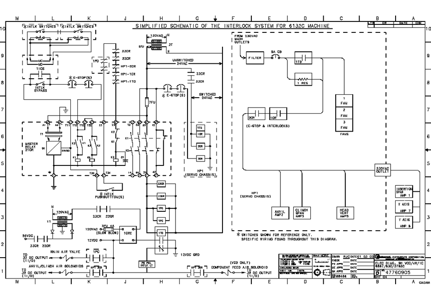
 Simplified Schematic of the Interlock System for 6241FSimplified Schematic of the Interlock System for Dual Head Axial Machines
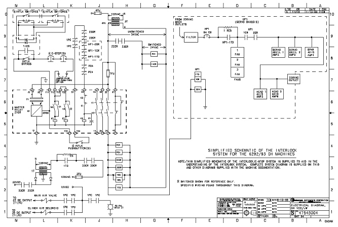 Simplified Schematic of the Interlock System for 6380A
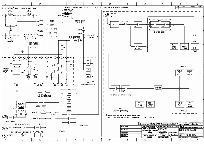
  |
Trace signals in the electrical schematics to answer the following questions.
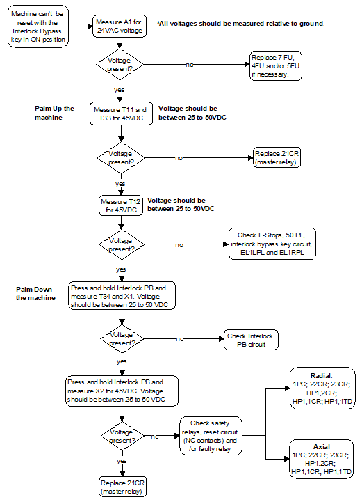
5FU-Side (SHT2) This question refers to the drawings for PS1, trace it from the secondary side of 2T (24V SEC) and is tied in with 5FU (sheet 2)
56VDC is supplied to 4TB Connects 56 VDC from secondary of 1T to 4TB distribution point to X-Y table motors.
the “ELECT DIAG, Power chassis” schematic Ask students: You lost 24VAC, where it’s generated from? (the inserter’s power chassis, PS1.) Where do you find that drawing? ELEC DIAG, Power Chassis. |
E-Stop Circuit Active |
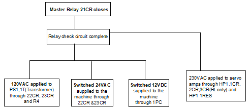

Direction
|
Instructor notes: the following table lists suggested bugs to simulate an E-stop and Interlock circuit problem. |
| Problem |
Simulation Method |
 24VAC to PS is lost 24VAC to PS is lost |
Remove 7FU, 4FU, or 5FU |
| 21CR can’t be energized | Disconnect X1 and X2 |
| Relay problem | Disconnect at contact 21 or 22 of 22CR and 23CR (Interlock system will not enable) |
| Cannot get out of interlock condition | Remove 6PL jumper plug at the back of PS1 |
| Cannot get out interlock condition | Remove wire T12 from 21CR relay block |
| No air to cylinders | Disconnect dump valve connector |
PCB Unloader \loader and Destacker from production to packaging.
PCB Unloader \loader and Destacker from production to packaging.
1. Purchase all kinds of materials according to order.
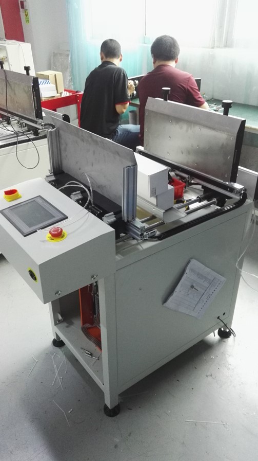
2. Frame installation of the entire machine.

3. Installed power motor
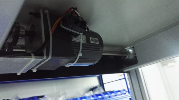
4. Install PLC control box.

5. Install sensor and belt.

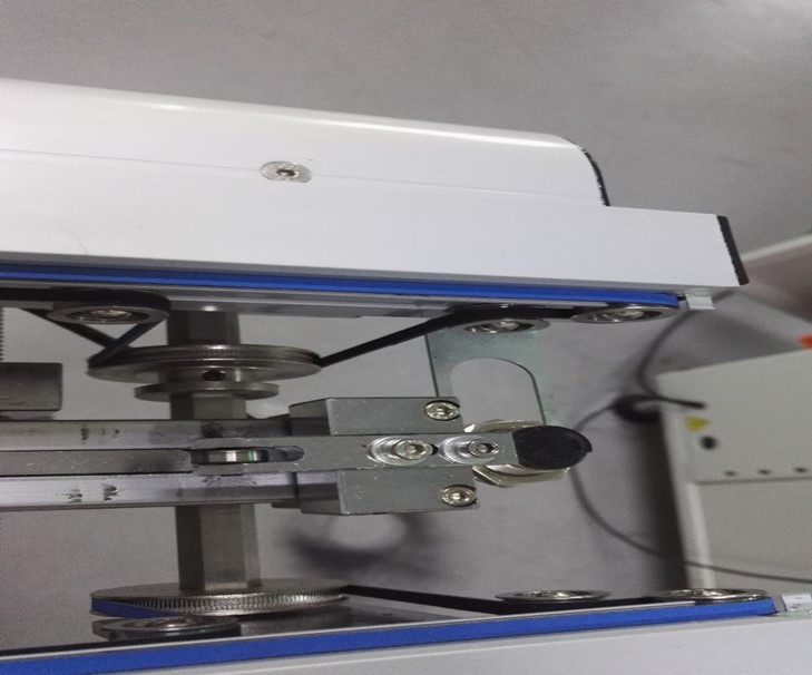
6.Install the cover
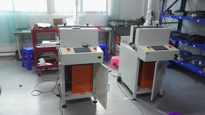
7.Install the LOGO

8. Install the program and test the machine.

9 .Use PCB board to test machine.
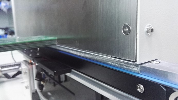

10.Use a magazine test machine.
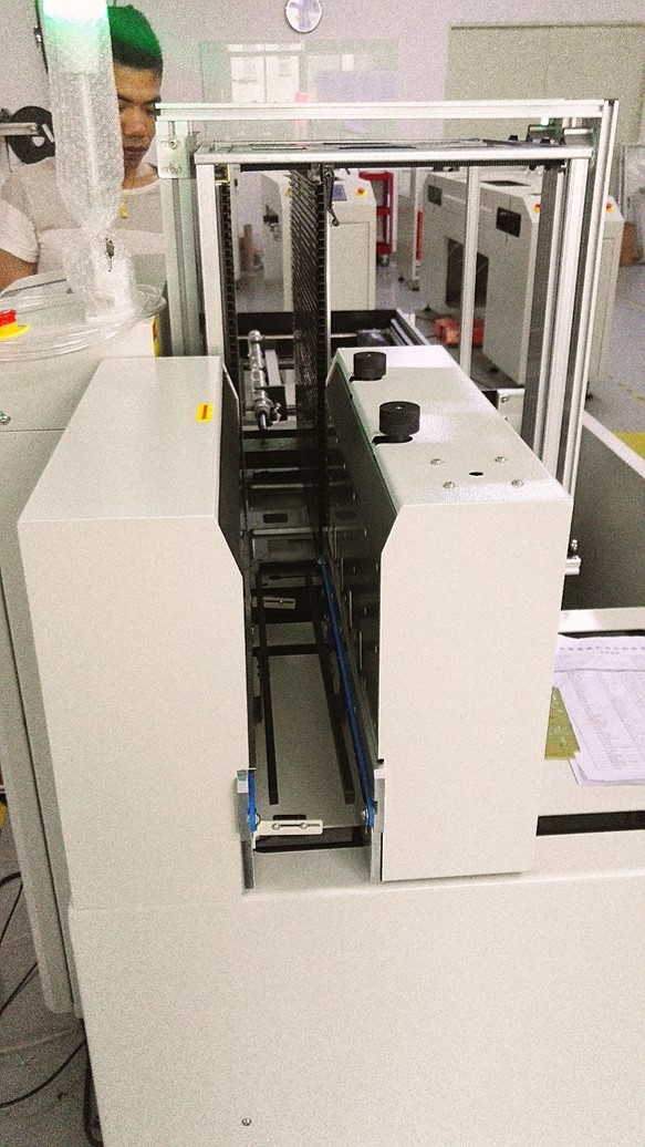
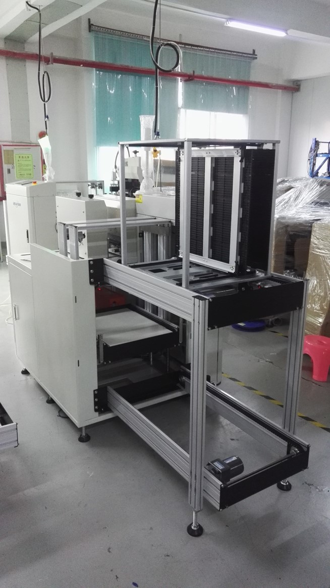

11. Aging operation week
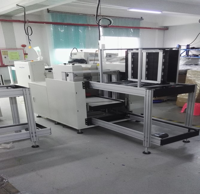

12. Simple packing before shipment.

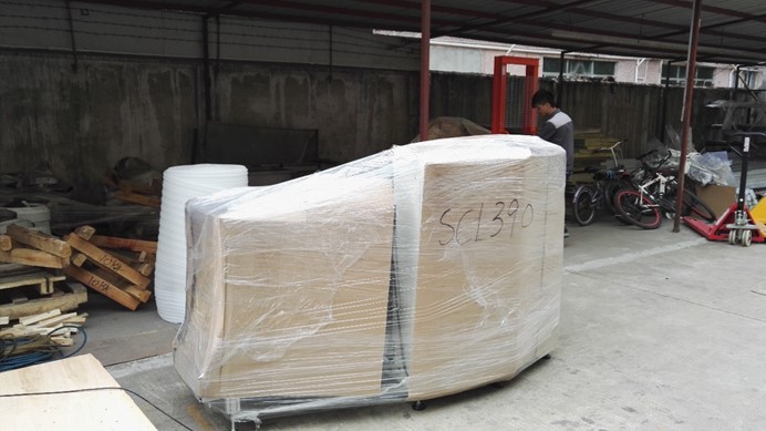
13. On the day of shipment, use the export wooden box vacuum packing,

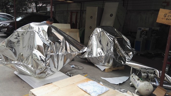

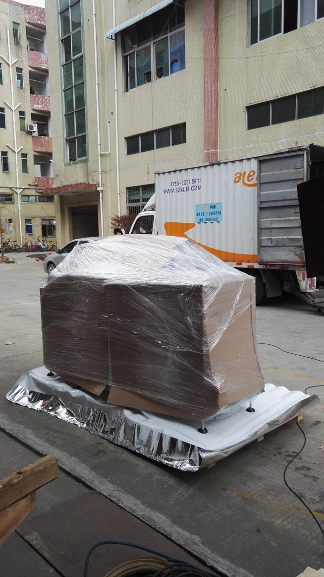

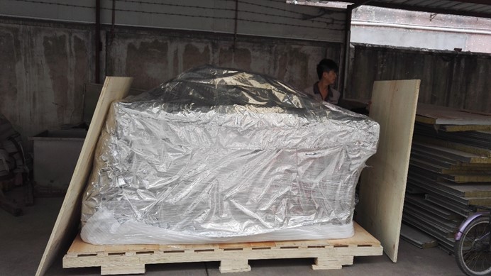


14. Arrange forwarders to pick up the goods.


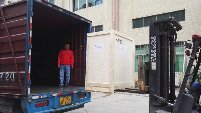
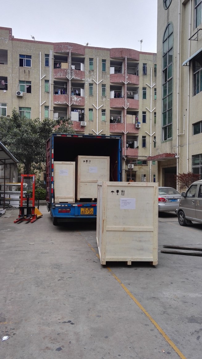
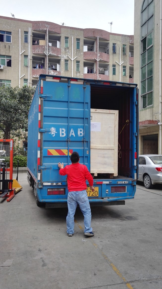

Four machines were shipped and shipped to the United States via freight forwarders.
ming@smthelp.com
S-CC200 User’s Manual for SMT CHIP Part Counter
S-CC200 User’s Manual for Part Counter
Index
-
Introduction…………………………. … ……. ….……..3
-
Attention for part counter……… ……………………. . 4
三、Chip bonder counter function key and operating instructions… ………………………………………………. …4
四、Chip bonder counter connecting printer operating instructions (Option) ……………………………… …………6
五、Trouble Shoot……….…………………….……………….8
六、After-sale service……………………………………….9
七、After-sale service card………….……… .. …………………..10
一、Introduction
1、Theory
Chip bonder counter can precisely count the SMD quantity, by adopting optical and electric sensor theory, using the corresponding relation between guide hole on the carrier and part, and by the special die and massive integrated circuit, chip bonder counter achieve zero error, and achieve convenient, quick counting, it is an effective auxiliary equipment for managing SMT material.
2、Product features
With full automatic way figure part quantity, it is convenient to count and delivery material. Easily operate it, original design defending strip dropping off decrease strip hurt to a smallest extent. It can count in forward direction or in backward direction, and it can be preset value, precisely figure out quantity with zero error. You also can install scanner gun and barcode printer, which is more convenient for managing operation..
3、product specification
Power: AC220V,50/60HZ,25W
Counter range: -99999–99999PCS
Profile size: L470W300H180mm
Weight: 10KG
4、Product Utility
Suit for SMD strip type of part
Strip wheel diameter: suit for any size
Strip pitch: 1,2,4,8,10,12,16,24,32,44,56mm ( Note: if pitch is smaller or wider, make it according to customer’s request)
Strip width: 4,6,8,12,16,24,32,44,56mm (Note: if width is smaller or wider, make it according to customer’s request)
5、Product Structure
this product have two types.
-
S-CC200 Standard chip bonder counter

2) S-CC202 inspecting missing type chip bonder counter

1、material reflector
2、Tray
3、Gear/motive pressing plate
4、monkey wrench
5、rocket head
6、free movable shoulder
7、location knob
8、display
9、key
10、power key
11、handle
12、glass fiber amplifier
13、glass fiber head to head emitter
二、Chip bonder counter attention
1,After unpacking, please count and make sure all accessories ready.
2,Before using chip bonder counter, please carefully read operating instructions and safe keeping.
3,Please check whether voltage specification conform to the electric supply.
4,Please check grounding properly, and guarantee safety of human body and part.
三、Chip bonder counter function key and operating instructions
1、Function key introduction
1)”PRINT”
Operation way: enter the key, you can print the counting part and quantity on the barcode by the barcode printer.
2)”SET”
Operation way: if the display shows 00000 in the left bottom, you can directly press the number key to input the counting part quantity; press the SET key one more time, the machine switches to manual mode, and the display shows ***** in the left bottom. Switch to manual mode or automatic mode using this key. (note: under automatic mode, you can preset a value before counting material, when machine turn to the presetting value, it will automatically stop, under manual mode, only if you press ” stop/zero clearing” key or it finishes all material, the machine will stop.)
3)”PITCH”
Operation way: after pressing this key, the pitch value in the display will flicker, then you can input the pitch value and press “ENTER” key, if no press after 5 second, automatically memorize, the machine will resume to standby status after one ticking sound.
4)”RIGHT” “FOREWARD/RIGHT”
Operation way: Pressing this key, start clockwise counting part, the numerical value is positive number, “BACKWARD/LEFT” on the contrary.
5) “STOP/ZERO CLEARING”
Operation way:
(1)Under counting or feeding back status, press this key, it will stop counting or feeding back.
(2)If under standby status, press this key over 2 second, the counting value will be cleared up.
(3)If under printing interface, press this key, return to main interface.
6)”SELECT”, this key is switching key for setting parameters in printing interface.
7)LCD display
 Set pitch
Set counting quantity part quantity
display*****under manual mode
8)”Time/missing stop” key is switching key for motor rotating speed, press this key, LCD display will show motor speed will be switched among H(high speed), M(middle speed), L(low speed).
2、 Operation Flow
1)Connect the power cable to the master machine, and plug the AC220V power.
2)Turn on the POWER key on the panel of machine, at this time, LCD panel become light
3)Press PITCH key, set the pitch between counting parts, then Press “ENTER”, and put the part on the left tray.
4)Manually pull out the strip and put it between material guard plate and counting gear, make the first part and blank middle hole aligning the middle line of material guard plate.
5)Press “STOP/ZERO CLEARING” key for 2 seconds, make the value zero clearing. Note: when pulling the strip, counting gear will turn and count, pressing this key, make the value zero clearing.
6)Press “SET” key to switch to manual mode or automatic mode, when you select automatic mode, you should input a value which you are going to count, or the “FORWARD” motor won’t start.
7)Pull strip coiling to the blank tray (right tray) by your hand, press “FOREWARD/RIGHT” to begin counting.
8)When finishing preset value, motor stop. Impacted by the inertia theory, counting number may be more one or less one than the set number,
9)When finishing counting, press “BACKWARD/LEFT”, strip will coil back to the left tray, after finishing, rotation will stop.
四、Chip bonder counter connecting printer operating instructions (Option)
1、Check equipment
1)Connect part counter and barcode master machine
2)Correctly place the barcode paper in the printer
2、 adjust and test equipment
1)Start power switch of the part counter
2)Start bar code master machine power switch: power pilot light and ready pilot light are on, at moment, press FEED key of bar code master machine (automatic aligning key), make the paper automatically align. ( P.S: if power light is flickering, it denotes the machine is off line, please restart power or repress FEED key)
3、Print
Press “PRINT” key in the master interface, master interface will display printing interface, the first row in the interface show: company name (you can set it by yourself); the second row show: time, the last row show printing operation.
-
When entering printing interface, there is a flickering cursor in the third row, you can edit and modify the content in the cursor position.
-
In the printing interface, pressing LEFT/BACKWARD, you can make the cursor move left, pressing RIGHT/FOREWARD, you can make the cursor move right.
-
In the cursor position, you can directly input the number or letter, if you continually press any key among 0~9 key in a short time, you can switch between number and letter on the key. Among of them, pressing 1 key, you can switch to special symbol, Capital letter, small letter, and etc.
-
After editing each row, cursor will stay in the row you are editing, press “ENTER” key, it will display OK in the left of this row, which means the content is saved.
Note: Saving the content in the editing row, only when cursor is in this row, and then press ENTER, the content can be saved. For example, if you want to save the content in the first row and second row, when cursor is in the first row, you press ENTER key, at the moment, only the content in the first row is saved, the content in the second row can’t be saved.
-
In the printing interface, press SELECT key into printing parameter setting interface, XYWH: XXX XXX XXX XXX showed in this interface separately denote X axis, Y axis, width, height which you can set to the printed barcode paper.
-
Press STOP/ZERO CLEARING back to master interface
-
Press PRINT key one more time, you can print the content in the printing interface.
Tag: when scanner scans barcode, it will display in the printing interface, press PRINT key to print.
五、Easy trouble shoot
| Failure | debug method |
| After turning on power, LCD no display, buzzer no sound | Please check if power cable drop off or fuse loosen |
| 。After turning on power, LCD no display, buzzer sound | LCD display cable loosens or breakdown, please check or contact dealer to change. |
|
LCD normally displays, but FOREWARD/BACKWARD can’t be started. |
|
六、After-sale service a: (overall unit maintenance period for one year, master controller board maintenance period for three years, and tended for all life.) the following state happened is not in the free maintenance condition.
-
Machine is damaged under carried by your person by himself
-
In unstable voltage region, due to not using voltage stabilizer, cause component damaged.
-
Due to not using correct voltage, cause component damaged
-
Not selled by our company, but selled by dealer or other factory.
-
Natural disaster, or act of God.
After-sale service card

 User’s Name: Address:

 Machine model: User’s phone number:

 Purchasing Date: Dealer’s seal:
User should know that:
- From the purchasing date on, overall machine will be maintained for one year, and tended for all life.
-
The following state is not in maintenance condition:
(1)Due to wrong operating, carelessly using, natural disaster cause the machine damaged.
- Due to operating abnormally, cause the machine not work properly.
- Once dismantled or repaired by someone who is not our technician.
- Using consumable supplies or component which are not from our company, cause the machine damaged.
- Not using the voltage required by our company, cause the machine damaged.
- Due to operating abnormally, cause the machine not work properly.
- Except this guarantee, any guarantee card supplied by other company or people won’t be approved by our company.
- Please safe keeping the card and formal purchasing receipt, when repairing, it will be effective after showing them to our people review.
- If the card has no commodity seal and purchasing date, the card automatically become invalid.

PCB board handling system Destacker Build Procedure
Destacker Build Procedure SDM0029
Rev A
1. Obtain the proper shop packet and check order for build information. Pull all parts if any parts are missing, fill out a shortage sheet and give a copy to the appropriate material coordinator.
2. Pull the latest Electrical and Mechanical prints.
3. The following procedure is for a 29″ Destacker. Attach leg and control box to main beam. Leg should be flush to left side of main beam. Control box should be 3″ from right side of main beam. Attach width units to main beam, 4-3/8″ from either end square to main beam and Parallel to each other.
4. The following procedure is for the 44″ and 58″ Destackers Attach leg and control box to main beam. Leg 7-5/8″ from left end control box 7-5/8″ from right end. Attach width units to main beam 8.975″ from either end. Square to main beam and parallel to each other.
5. Attach rear rail to width supports parallel to main beam 3/8″ overhand from either end of main beam.
6. Level conveyor from side to side and front to back, off rear rail
7. Attach front rail to width supports. Match level to rear rail, especially front to back. Make parallel to rear rail. Make ends even with rear rail.
8. Install motors, pulleys, UHMW and belts on rails.
9. Attach Destacker assy to rails
10. Assemble valve pack assy and install
11. Attach air input assy
12. Attach front cover and wire into control box
13. Run pneumatic lines, load program software and test.
14. Complete check sheet, turn over to QC
End of Document