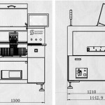
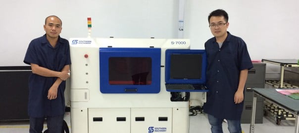
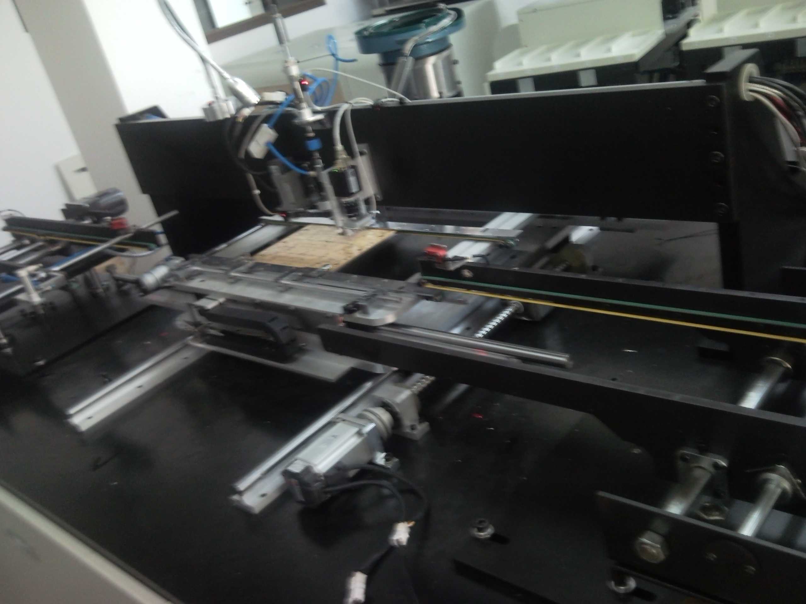
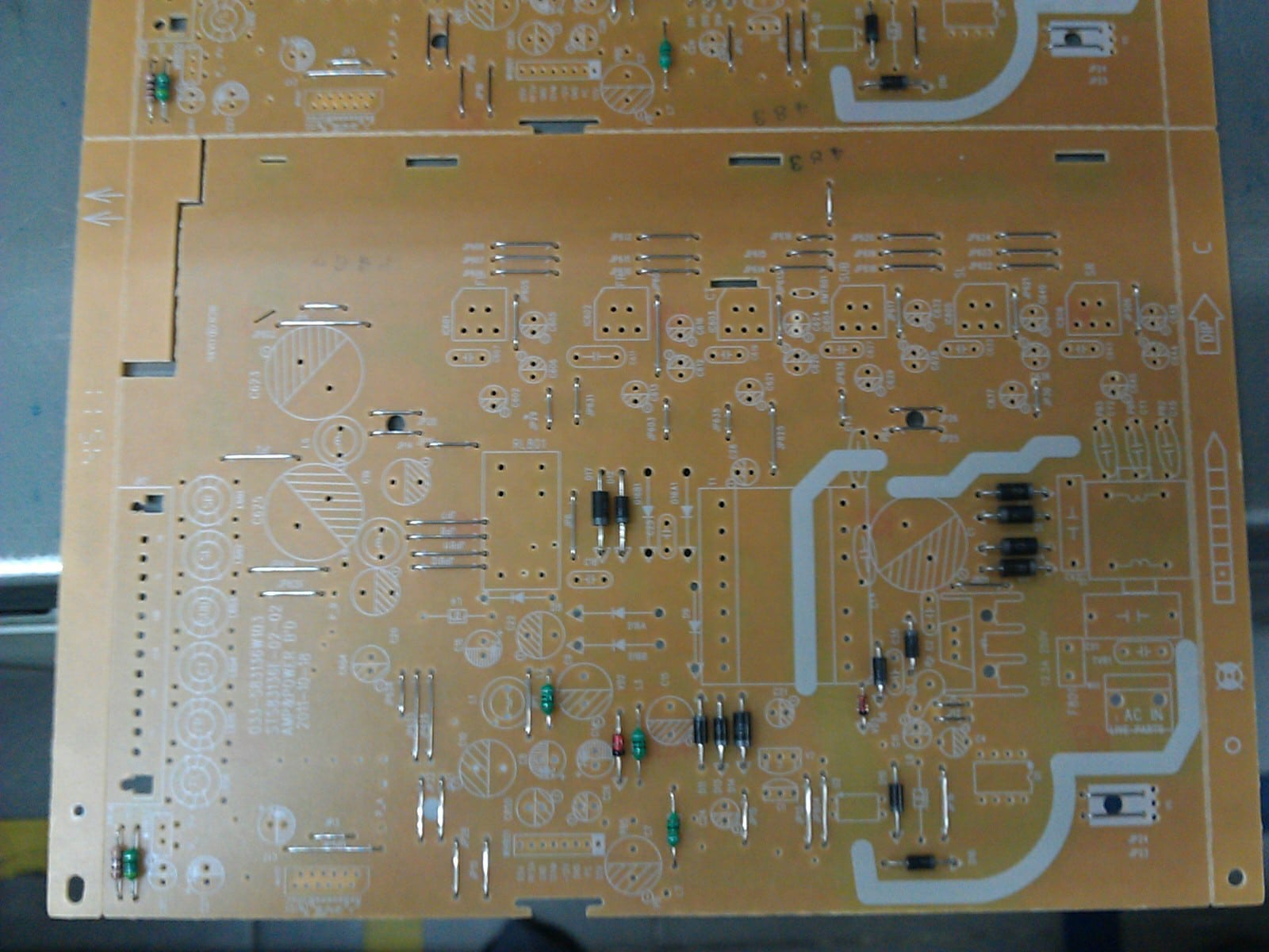
AI, Auto Insertion : Axial Inserter; Radial Inserter; JW (Jumper Wire) Inserter; Odd form Inserter; PIN inserter; Eyelet Inserter; Terminal Inserter IM, Insertion Mount, MI,Manual Insertion, DIP, Wave soldering 5, SMT - Souface Mount Technology: BHS: PCB board handling system, Loader, Unloader, Conveyor,Shuttle Printer: Solder paste screen printer SPI: Solder Paste Inspection Mounter: Chip Mounter, Pick and Place, IC Mounter, High Speed Mounter AOI Reflow Oven

Auto Insertion machine CPU board EPC-1316 Boot Sector and BIOS Corruption Procedure for Re-flash

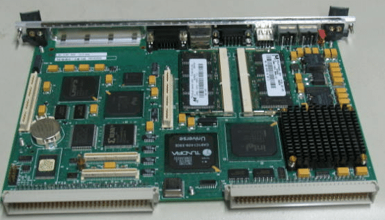
48797301 board
Procedure

Symptoms of corrupted BIOS and/or Boot Block:

  • No video signal from the EPC-1316
  • No activity on
  1. The keyboard, no status lights at power-on
  2. The floppy drive with a disk in or out
  3. The hard disk drive evident by the light off after a certain amount of time
  • The EPC-1316 is trying to access the CD-ROM drive with failed attempts every second or so.
  • The EPC-1316 is in this cycle indefinitely

Steps to take:

  1. Power down the EPC-1316 board/machine.
  2. Make sure that this instructions file is opened on a different computer.
  3. At the last step of these instructions is an embedded object of the .zip folder; it contains all of the files needed for this procedure.
  4. Right click on the .zip folder, select ‘Package Object’ and click on ‘Activate Contents’. If a message regarding a trustworthy source is displayed, confirm that this source can be trusted
  5. Create a new folder on the Desktop and rename it to “EPC-16FBD1.00.10”
  6. Click ‘File’, then select and click on ‘Extract All…’
  7. Extract the .zip folder into the folder on the Desktop, created in Step 3.
  8. Obtain a 3.5in Floppy Disk and insert it into the drive.
  9. Open the “EPC-16FBD1.00.10” folder from the Desktop
  10. To run an MS-DOS program, double click on the CRISDISK.BAT file.
  11. To run a Windows Application, double click on the WINCRIS.EXE file.
  12. Go through prompts of the program attentively; and a crisis disk will be created.
  13. Remove the EPC-16 board from the VME chassis/rack.
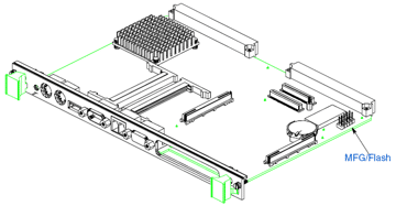
  14. At the bottom of the board there are 2 x 5 jumper pins: MFG/Flash. (Figure 1)


Figure 1 EPC-1316 Board jumper pin location

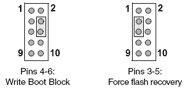
  1. See Figure 2 for PIN-out of the Jumper pins.


Figure 2 EPC-1316 Board jumper pin numbering

  1. Using 2 jumpers (Figure 3): place one to jumper pins 4-6. (jumper setting ‘Write Boot Block’)
  2. Place the second to jumper pins 3-5. (jumper setting ‘Force flash recovery’)


Figure 3 EPC-1316 Board flash jumpers configuration

  1. Replace the EPC-1316 board to the VME chassis/rack.
  2. Insert the 3.5in Floppy Disk that was created from the steps above into the floppy drive.
  3. Power-up the machine/chassis/EPC-1316.
  4. If the status light on the floppy drive comes on and stays on, then the floppy disk is being accessed.
  5. When the floppy drive stops accessing the Floppy Disk, wait about 5 seconds, and then remove the disk.
  6. Power down the EPC-1316, and remove it from the VME interface.
  7. Remove jumpers from the board and replace the board to the VME interface.
  8. Power-up the machine/chassis/EPC-1316 and make sure that it boots the operating system.
  9. Refer to UIC procedures for proper BIOS settings/ configuration


UIC, EPC-1316 Boot Sector and BIOS Corruption Procedure for Re-flash

Procedure

Symptoms of corrupted BIOS and/or Boot Block:

  • No video signal from the EPC-1316
  • No activity on
  1. The keyboard, no status lights at power-on
  2. The floppy drive with a disk in or out
  3. The hard disk drive evident by the light off after a certain amount of time
  • The EPC-1316 is trying to access the CD-ROM drive with failed attempts every second or so.
  • The EPC-1316 is in this cycle indefinitely

Steps to take:

    1. Power down the EPC-1316 board/machine.
    2. Make sure that this instructions file is opened on a different computer.
    3. At the last step of these instructions is an embedded object of the .zip folder; it contains all of the files needed for this procedure.
    4. Right click on the .zip folder, select ‘Package Object’ and click on ‘Activate Contents’.  If a message regarding a trustworthy source is displayed, confirm that this source can be trusted
    5. Create a new folder on the Desktop and rename it to “EPC-16FBD1.00.10”
    6. Click ‘File’, then select and click on ‘Extract All…’
    7. Extract the .zip folder into the folder on the Desktop, created in Step 3.
    8. Obtain a 3.5in Floppy Disk and insert it into the drive.
    9. Open the “EPC-16FBD1.00.10” folder from the Desktop
    10. To run an MS-DOS program, double click on the CRISDISK.BAT file.
    11. To run a Windows Application, double click on the WINCRIS.EXE file.
    12. Go through prompts of the program attentively; and a crisis disk will be created.
    13. Remove the EPC-16 board from the VME chassis/rack.
    14. At the bottom of the board there are 2 x 5 jumper pins: MFG/Flash. (Figure 1)

Figure 1 EPC-1316 Board jumper pin location

    1. See Figure 2 for PIN-out of the Jumper pins.


Figure 2 EPC-1316 Board jumper pin numbering

    1. Using 2 jumpers (Figure 3): place one to jumper pins 4-6. (jumper setting ‘Write Boot Block’)
    2. Place the second to jumper pins 3-5. (jumper setting ‘Force flash recovery’)

Figure 3 EPC-1316 Board flash jumpers configuration

    1. Replace the EPC-1316 board to the VME chassis/rack.
    2. Insert the 3.5in Floppy Disk that was created from the steps above into the floppy drive.
    3. Power-up the machine/chassis/EPC-1316.
    4. If the status light on the floppy drive comes on and stays on, then the floppy disk is being accessed.
    5. When the floppy drive stops accessing the Floppy Disk, wait about 5 seconds, and then remove the disk.
    6. Power down the EPC-1316, and remove it from the VME interface.
    7. Remove jumpers from the board and replace the board to the VME interface.
    8. Power-up the machine/chassis/EPC-1316 and make sure that it boots the operating system.
    9. Refer to UIC procedures for proper BIOS settings/ configuration


PCBA Quality Process Audit — SMT Pick and Place machine

1. Work Instructions
1.1 Is there a revision controlled Operator Work Instruction which contains loading information for the specific product being built? (Score 0 if any unsigned/undated handwritten instructions or any handwritten instructions more than 48 hrs old)
1.2 Are Work Instructions readily available to the operator and are they followed at Component Placement?
1.3 Are component part numbers and descriptions included on the Work Instructions?
1.4 Are component descriptions sufficiently detailed to check at first-article that the correct components are being used?
1.5 Is the machine head/slot number for component loading specified for each part number on Work Instructions?
1.6 Are the reference designators and the quantity per part number specified on Work Instructions?
1.7 Is the component feeder type/size specified on Work Instructions or otherwise for each component package type?
1.8 Is the machine Program Name specified on the Work Instruction or line set-up instructions?
2. Component Loading and Verification
2.1 Is there an automated bar coded component loading verification aid in order to reduce the probability of incorrect loading? Note*
2.2 Are the component loading verification aids hard linked to the placement program so that loading is verified against program data?
2.3 Can traceability of component lot codes be demonstrated for critical devices?
2.4 Is component loading/changes verified and cross checked by an individual other than the set-up operator at product changeover? Note*
2.5 Is a component loading/changes verification log signed by the set-up operator and countersigned by the cross checker before start up? Note*
2.6 Is the correct feeder loading base used to facilitate real to feeder loading?
2.7 Are first-built boards verified against documentation for missing/misplaced components and for correct component polarity?
2.8 Are first-articles conducted using AOI methods and complemented with description verification and value metering?
2.9 Are all Resistors & Capacitors measured for a value within the tolerance (one per part number) at first-article & at reel change?
2.10 Is a first-article log signed to verify acceptance before start up?
2.11 Is the orientation of Tantalum SMT capacitors, Diodes, etc in tape format, standardized and documented for polarity orientation?
2.12 Is the IC tray loading polarity standardized for each type of polarity indicator that can be used for each component?
2.13 Is loading polarity referenced both from the tray and the component so as to ensure retrayed components are correctly loaded?
3. Nozzles, Feeders, and Tooling
3.1 Is there a document which details the standardized nozzle diameter set-up selected for each type of placement equipment?
3.2 Are these standardized nozzle diameter set-up documents readily available for when nozzles need to be replaced or changed?
3.3 Is there a document which details the range of component XYZ body sizes that each selected nozzle type can successfully place?
3.4 Is there a documented requirement to conduct daily nozzle centering and is there evidence that this is done?
3.5 Is each feeder identified with its own unique serial number?
3.6 Is there a documented and effective Feeder Maintenance Program? Records (s/w or otherwise) must be by Feeder Serial Number.
3.7 Are database records maintained for each feeder serial number for the purpose of tracking its maintenance history and performance?
3.8 Is feeder maintenance history used to monitor feeder life so that problematic feeders can be removed from the process?
3.9 Can it be demonstrated that the number of feeder indexes is counted & monitored for each unique feeder using software or otherwise?
3.10 Is this information used to flag that feeder preventative maintenance is required after x number of indexes?
3.11 Is there a documented requirement to indicate that Blocks or Support Pins are needed for specific products?
3.12 Is the No, location, type and height of Support Blocks/Pins identified on a product by product basis? Score NA if in 3.11 there are not needed.
3.13 Are the Support Pin locations identified for each product using templates/tooling or some other effective solution? Comment as above.
4. Moisture Sensitive Devices
4.1 Are components stored before loading and after unloading in a manner which prevents damage?
4.2 Are the Moisture Sensitive Devices (MSDs) and their sensitivity level readily known to the operator?
4.3 Are MSDs time stamped at opening and their exposure time monitored against pre determined limits?
4.4 Is there a flag to indicate that the exposure time has been exceed for any given device in a dry box?
4.5 Is there a flag to indicate the MSD exposure has expired for any MSD device currently loaded in the placement machines?
4.6 Have MSD procedures been updated to reflect the JEDEC standard for MSD control? (J-STD-033A MSD released in July 2002)
4.7 Is there evidence of correct implementation of J-STD-0033A for all MSD devices?
4.8 Are there MSD procedures in place to ensure MSD shelf life is reduced based on measured Relative Humidity conditions?
4.9 Is there a method in place to address the time spent in dry storage and its effect on remaining life based on MS Level and RH Level?
4.10 Is it clearly understood that MSD ‘shelf life’ continues to degrade during dry cabinet storage of some MSD devices?
4.11 If MSDs are on both sides of a PCBA, is there an effective method to account for time between 1st and 2nd reflow?
4.12 Can MSD control be demonstrated for MSD devices that need internal/external pre-programming?
4.13 Can MSD control be demonstrated for rejected devices and devices used for rework?
4.14 Have MSD recovery methods been defined and adequate for all component types?
4.15 Does the control of Moisture Sensitive Components include those components on reels?
4.16 Is the baking or hot room storage time and temperature documented and controlled for component recovery?
4.17 Has this time and temp been determined based on the component supplier’s guidelines / J-STD-0033A?
4.18 Is there evidence to demonstrate that the control process for MSDs is in use and is effective?
5. Machine Capability
5.1 Are Component Placement Programs generated from CAD XY coordinate data?
5.2 Is there a standardized nomenclature for Shape Code definition?
5.3 Can this nomenclature be used to determine the most appropriate shape code to allocate to a given part of given dimensions?
5.4 Are localized fiducials used for fine pitch devices when localized component fiducials exist on the board?
5.5 Has manual component moving been eliminated given correct CAD, nozzle set-up, Shape Code allocation, local fiducials, Cam speed, etc?
5.6 Does the Fine Pitch placement machine have the capability to check lead Coplanarity in xyz?
5.7 Does the Fine Pitch placement machine use its coplanarity capability on all leads of 20 mil pitch or less, and all programmed parts?
5.8 Does the Fine Pitch placement machine have the capability to check ball arrays? If no such device, score NA.
5.9 Does the Fine Pitch placement machine use its ball array verification capability for all BGA devices? If no such device, score NA.
5.10 Is the machine Program Name revision controlled to show traceability of program changes?
5.11 Is the machine Program Name traceable to the PWB and PCBA part number?
6. PCBA
6.1 Are outputted boards at least sample inspected pre reflow for placement positional accuracy for machine control purposes?
6.2 Is the frequency for this verification defined and documented, and is there evidence to suggest it is followed?
6.3 Is there a visual aid available which identifies the populated locations with polarity, and also the no-pop locations?
6.4 Is there a placement standard pre reflow to validate placement accuracy for the shape code, nozzle allocation, etc. parameters used?
6.5 Is there evidence to demonstrate that action is taken to adjust the machines performance for when this standard is exceeded?
7. Attrition Rates and Rejected Components
7.1 Is attrition rate monitoring conducted systematically to ensure feeder and/or nozzle problems are captured at least hourly?
7.2 Is there documented evidence to ensure attrition rates are checked and actioned at least hourly to ensure process control?
7.3 Is there a specification defined for acceptable attrition rates for the individual feeders?
7.4 Is there a specification defined for the maximum allowable number of nozzle skips per machine before it is shut down for repair?
7.5 Are these specifications determined based on a percentage combined with the number of placements for a given time period?
7.6 Is there evidence to demonstrate that attrition rate monitoring is conducted, effective, and used to make process control decisions?
7.7 Is there a documented process for the disposition or reuse of machine rejected components? Rs and Cs must not be reused even for rework.
7.8 Are rejected components reviewed and repaired to ensure conformance before reuse, even if only used for rework?
7.9 Are there repair blocks available or a lead conditioner in use for repairing ‘real’ Coplanarity rejects? Score 0 if parts not repaired.
7.10 Does the re-traying process always ensure that component polarity wrt the tray and the component loading polarity is preserved?
7.11 Is there a documented Process Deviation procedure to manage machine skips for hand placement if hand placement is allowed?
8. Process Capability
8.1 Has a Process Capability Analyses (PCA) been conducted and the Cpk acceptable for the suite of shape codes in use?
8.2 Were shape code allocations, component nozzle allocations, cam speeds, etc. recorded for this PCA?
8.3 Are the recorded shape code allocations, component nozzle allocations, and cam speeds, the same as those used today?
AI spare parts、Universal Parts,UIC,TDK.VCD Sequencer.SMT,THT,PCB,PCBA,AI,wave soldering,reflow oven,nozzle,feeder,wave soldering,PCB Assembly, LED, LED lamp, LED display

2 video to compare manual and automatic component lead cutting for electronic manufacturing PCBA

SAVE YOUR TIME & SAVE YOUR MONEY
 
While decide to purchase SMT Pick and Place Machine ! 
 
let us instruct you and provide you complete suitable SMT/THT machines according to your choice and requirements with a comprehensive Buyers’s Guide to save your time and Money. To search Out for your company’ which Pick and Place machine is best suited to your production needs – and your Budget. 
 
Southern Machinery Helps you : 
  • Identify your production requirements and your needs. 
  • Make sense of your equipment specifications. 
  • Calculate your speed and feeder needs. 
  • Create equipment benchmarks and apple to apple comparison of models and brands. 
  • Provides machines and spare parts according to your choice and specifications with a comprehensive Buyers Guide. 
  • Short time delivery period with affordable price. 
  • Training on site from 20- years expert team.
  • Many more ………………..


Electronic component lead cutting by Manual

Automatic Electronic component lead cutting


AI spare parts、Universal Parts,UIC,TDK.VCD Sequencer.SMT,THT,PCB,PCBA,AI,wave soldering,reflow oven,nozzle,feeder,wave soldering,PCB Assembly, LED, LED lamp, LED display

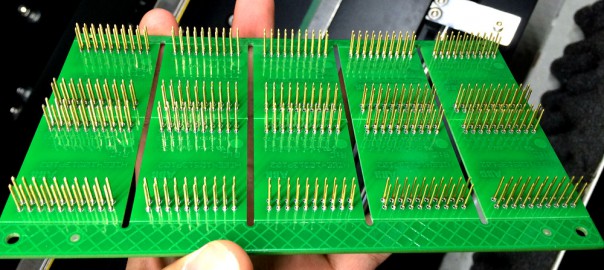
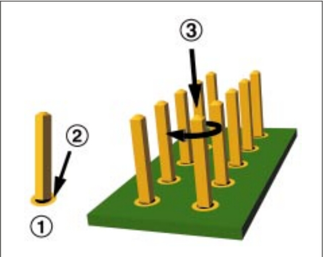
2 video to compare Manual and Auto PIN/ Eyelet/Terminal insertion for electronic manufacturing PCBA

The Through Hole Assembly, also known as thru hole assembly, process uses the latest models with the quickest possible turnaround rate in the industry. Assembling excellent stable sequencing performance with easy operating software utilizing its high precision through hole assembly both by hand and automation to create electronic solder connections.


C (20121106 212843894) Audio003

Automatic PIN/ Eyelet/Terminal insertion:

ManualPIN/ Eyelet/Terminal insertion:

AI spare parts、Universal Parts,UIC,TDK.VCD Sequencer.SMT,THT,PCB,PCBA,AI,wave soldering,reflow oven,nozzle,feeder,wave soldering,PCB Assembly, LED, LED lamp, LED display

One Video let you know how Radial Insertion works for Electronic through-hole components assembly

  • Radial Insertion – A radial inserter takes radial leaded through-hole components from reels and creates a sequence of components in order of insertion. Then the machine auto inserts the components into the PCB. The machine can be programmed to bend and cut leads per customer/component specifications.


One Video show you China Made LED chips SMT pick and place machine

2015 new designed LED light board pick and place assemble machine   :

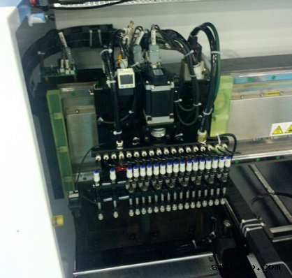
Mounting head: Double arm, 36 pieces sucking mouth, 18 pieces sucking mouth per arm

Min mounting distance: 13.5mm

Driving motor of mounting head(Y axis): Principle motor(magnetic), 15% faster than servo screw motor

Mounting range: 0805,1206,2121,2835,3014,3528,5050,5630,5730,RGB and other LED belt light

Theory mounting speed: 70K CPH*2=140K CPH

Working mounting speed: 60K CPH*2=120K CPH

PCB sizes:1200MM(L)-300MM(W)

Feeder amount: 18 feeder(8mm)*2=36 feeders,electronic feeder

Vibrating disc, for bulk material: Can be customized, vibrating disc can be changed with FEEDER, and the

working speed is the same

Dimension(L*W*H): 2650*1650*1350mm

Total weight: 2000kg

Application: 0.3-1.2 meter LED daylight tube and soft light belt include RGB strip light, LED panel light etc


Model Pick and place speed Overall sizes( L*W*H) Weight
S-K100 Belt LED SMD 120K CPH 2650*1650*1350mm 2000kg
S-K200 Belt LED SMD 180K CPH 2650*1750*1400mm 2500kg
S-K100VP Bulk LED SMD 80K CPH 2650*1650*1350mm 2000kg
Detailed Images

Fully automatic electric feeder, can set the feeding design according to your mounting needs through the computer:

The highest capacity LED light board pick and place assemble machine


Double module mounting head, each module has 16 pieces sucking head:

The highest capacity LED light board pick and place assemble machine


South Korea magnetic motor, guarantee high mounting speed, easy to maintain:

The highest capacity LED light board pick and place assemble machine


Top performance industry computer, can be folded into the machine, easy to set placing design:

The highest capacity LED light board pick and place assemble machine


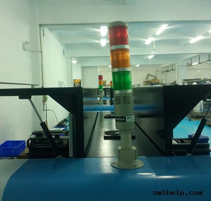
Skoda alarm, let you know the pick and place machines working condition clearly:

The highest capacity LED light board pick and place assemble machine


AI spare parts、Universal Parts,UIC,TDK.VCD Sequencer.SMT,THT,PCB,PCBA,AI,wave soldering,reflow oven,nozzle,feeder,wave soldering,PCB Assembly, LED, LED lamp, LED display

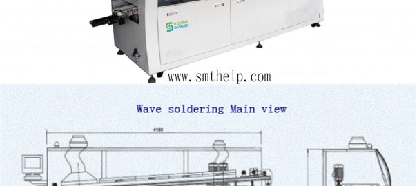
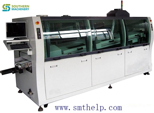
S-ws250 Wave soldering machine for electronic manufacturing PCBA

Lead-free or Tin-lead Through-hole Soldering

adjustable dual waves permit lead-free or tin/lead processing of through-hole and SMD boards to a maximum width of 250 mm

As PCBs are loaded onto the adjustable titanium finger conveyor, they are automatically prepped by an adjustable internal spray fluxing system which houses a precision spray nozzle assembly mounted to a reciprocating Y-axis drive mechanism to ensure even and accurate application of flux.

Run as Dual or Single Wave

Solder processing temperature is settable to a lead-free compatible 300°C. The system includes an economical low-volume 200 kg (550 lbs. Approximate weight for lead free solder) capacity solder pot with an easy-handling roll-out feature. A built-in alarm signals when solder level is at the refill point.

Forced Hot Air Convection Pre-Heat

The preheat stage takes place in a 600 mm (23.6″) glass-covered chamber where boards are heat-bathed by energy-saving forced hot air convection, as opposed to power-consuming, uneven IR heat.

AI spare parts、Universal Parts,UIC,TDK.VCD Sequencer.SMT,THT,PCB,PCBA,AI,wave soldering,reflow oven,nozzle,feeder,wave soldering,PCB Assembly, LED, LED lamp, LED display


Automatic spray fluxer produces uniform fine spray coverage of underside of each incoming board. Integrated cooling zone provides rapid cooling for processed boards prior to exiting the conveyor.
Energy-conserving 600 mm (23.6”) forced hot air convection preheater safely preps boards for higher temperatures of lead-free or tin-lead soldering while ensuring that fluxes are properly activated. Process area—where dual waves are generated by titanium alloy wave nozzles.
Preheat area remains enclosed under glass during processing, preventing escape of hot air. With front panel removed, dual solder pumps (top) and solder pot below are exposed. Electrical panel is accessed by removing cabinet door on right side.
Cooling fans apply focused below-board heat to quickly lower temperatures of processed boards. Titanium-alloy wave nozzle and components resist corrosion. Finger conveyors are automatically cleaned prior to loading of each board.
Titanium finger conveyor is hand-crank adjustable to boards of up to 350 mm width. Titanium finger conveyor is hand-crank adjustable to boards up to 350 mm width. Fingers are self cleaning.
Built-in flux fume exhaust hood and filter. Flux vapors are extracted through a built-in fume hood and filter, and out of the system through an exhaust flange on the top of the unit. The filter is easily removable for cleaning. A tote case containing all hand tools necessary for maintenance, repair or disassembly
AI spare parts、Universal Parts,UIC,TDK.VCD Sequencer.SMT,THT,PCB,PCBA,AI,wave soldering,reflow oven,nozzle,feeder,wave soldering,PCB Assembly, LED, LED lamp, LED display,

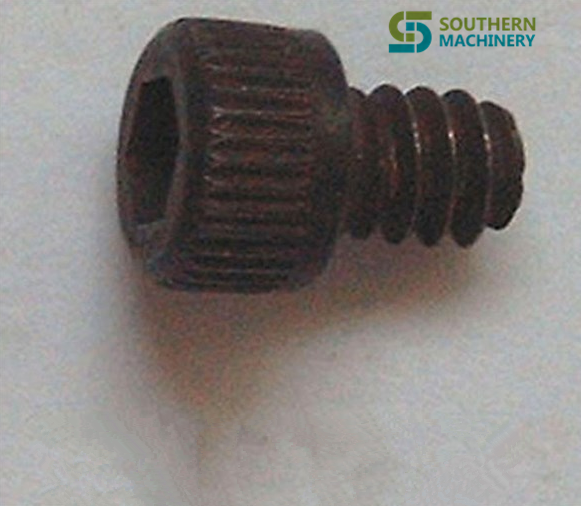
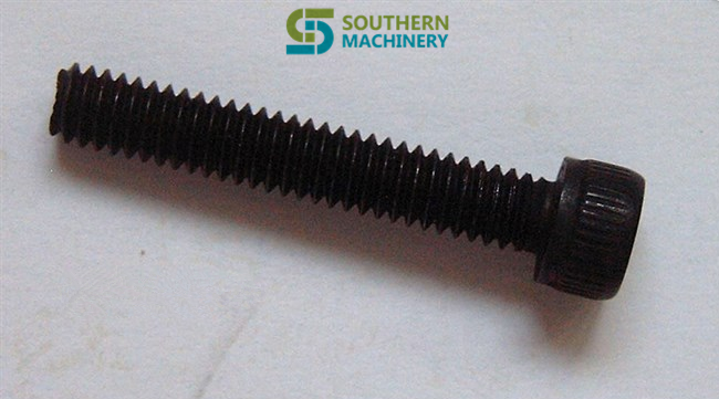
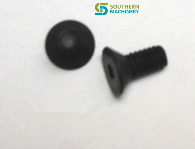
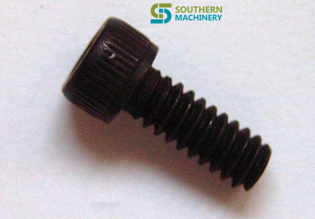
Universal Auto Insertion machine spare parts – SCREW


Nuts
42519400 Hex Nut *
42519500 Hex Jam Nut *
42519600 Hex Nut – Machine Screw HEXNUT-MS
42519700 Hex Nut – Small Pattern HEXNUT-SP
42519800 Hex Nut – Metric *
42519900 Hex Nut – Nylon HN-N
42555700 Hex Nut – Left Hand Thread HN-LHT
42520000 Square Nut – Standard SQNUT-STD
42520100 Square Machine Screw Nut SQMSNUT
Socket Button Head Screws
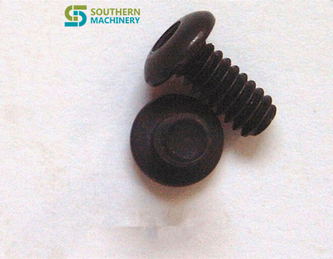
42520200 Socket Button Head Screw SBHS
42520300 Socket Button Head Screw SBHS-NP
W/Nylon Patch
42520400 Metric Socket Button Head MSBHS
Screw
Hex Head Screw
42520500 Hex Head Cap Screw HHCS
42520600 Hex Head Machine Screw HHMS
42521200 Metric Hex Head Machine MHHMS
Screw
42522100 Lag Screw LAG SCR
42555300 Hex Head Cap Screw – Full HHCS-FTHD-SMHD
Thread – SMHD
Socket Head Cap Screws
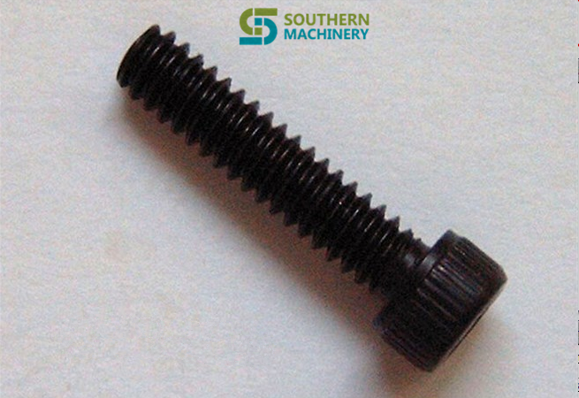
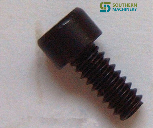
42520700 Socket Head Cap Screw SHCS
42520800 Socket Head Cap Screw SHCS-NP
W/Nylon Patch
42520900 Socket Head Cap Screw SHCS-SS
Stainless Steel
42521000 Socket Head Cap Screw SHCS-LH
Low Head
42521100 Metric Socket Head Cap MSHCS
Screw
42521300 Socket Head Cap Screw SHCS-N
Nylon
42554900 Metric Socket Low Head Cap MSLHCS
Screw
Flat Head Screws
42521400 Flat Head Machine Screw FHMS
42521500 Flat Head Wood Screw FHWS
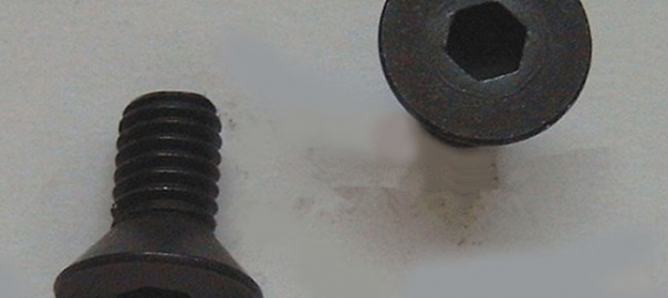
42521600 Socket Flat Head Screw SFHS
42521700 Socket Flat Head Screw SFHS-NP
W/Nylon Patch
42521800 Metric Socket Counter Sink MSCS
Screw
42521900 Flat Head Self Tap Screw FHSTS-TA
Type – A
42522000 Slotted Flat Head Screw *
Nylon
42555400 Flat Head Thread Cutting FHTCS
Screw
42555600 Flat Head Machine Screw 100 FHMS-100 DEGREE
Counter Sunk
Pan Head Machine Screw
42522200 Pan Head Machine Screw PHMS
42522300 Pan Head Self Tapping Screw PHSTS-TA
Type-A
42522400 Pan Head Self Tapping Screw PHSTS-TF
Type-F
42522500 Metric Pan Head Machine Screw MPHMS
42522600 Pan Head Screw – Nylon PHS-N
42555000 Pan Head Self Tapping Screw PHSTS-T25
– Type 25
42555500 Pan Head Thread Cutting Screw PHTHCS
Round Head Screws
42522700 Round Head Drive Screw RHDS-TU
– Type U
42522800 Round Head Machine Screw RHMS
42522900 Round Head Wood Screw RHWS
42566000 Round Head Square Neck Bolt RHSNB
Set Screws
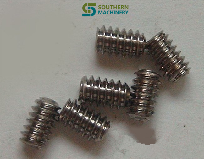
42523000 Socket Set Screw Cone Point SSSCNP
42523100 Socket Set Screw Cup Point SSSCPP
42523200 Socket Set Screw Cup Point SSSCPP-NP
W/Nylon Patch
42523300 Socket Set Screw Flat Point SSSFP
42523400 Socket Set Screw Half Dog Point SSSHDP
42523500 Socket Set Screw Knurl Cup Point SSSKCPP
42523600 Socket Set Screw Oval Point SSSOP
42523700 Socket Set Screw Cup Point SSSCPP-SS
Stainless Steel
42523800 Metric Socket Set Screw Cup Point MSSSCP
Shoulder Screws
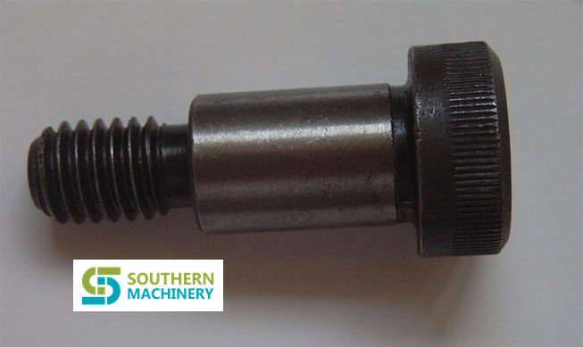
42523900 Socket Head Shoulder Screw SHSS
42524000 Metric Socket Shoulder Screw MSSS
10463000 Shoulder Screws *
Washers
42524100 Flat Washer FW
42524200 External Tooth Lock Washer ETLW
42524300 Internal Tooth Lock Washer ITLW
42524400 Split Lock Washer SLW
42524500 Metric External Tooth Lock Washer MITL
42524600 Metric Flat Washer MFW
42524700 Flat Head External Tooth Lock FHETL
Washer
42524800 Split Lock Washer, Black SLW-BLACK
42524900 Flat Washer, Black FW-BLACK
42555100 Machine Screw Flat Washer MS-FW
Pins
42525000 Standard Dowel Pin SDP
42525100 Oversize Dowel Pin ODP
42525200 Pull Dowel PD
42525300 Dowel Pin – Pic DP-PIC
42525400 Spring Pin SPRG PIN
42525500 Taper Pin *
42525600 Metric Standard Dowel Pin MSDP
42525700 Metric Spring Pin MSP
42555200 Spirol Pin – Pic SP-PIC
Inserts
42525800 Heli-coil Insert *
AI spare parts?Universal Parts,UIC,TDK.VCD Sequencer.SMT,THT,PCB,PCBA,AI,wave soldering,reflow oven,nozzle,feeder,wave soldering,PCB Assembly, LED, LED lamp, LED display,
80011303 SCREW, SHOULDER SHSS 1.2×3.4
AI spare parts?Universal Parts,UIC,TDK.VCD Sequencer.SMT,THT,PCB,PCBA,AI,wave soldering,reflow oven,nozzle,feeder,wave soldering,PCB Assembly, LED, LED lamp, LED display,
80007204 SSSOP 1.4-20 X 3.4
AI spare parts?Universal Parts,UIC,TDK.VCD Sequencer.SMT,THT,PCB,PCBA,AI,wave soldering,reflow oven,nozzle,feeder,wave soldering,PCB Assembly, LED, LED lamp, LED display,
80004602 SSS 4-40×3.16
AI spare parts?Universal Parts,UIC,TDK.VCD Sequencer.SMT,THT,PCB,PCBA,AI,wave soldering,reflow oven,nozzle,feeder,wave soldering,PCB Assembly, LED, LED lamp, LED display,
80001301 SBHS 4-40×1.4
AI spare parts?Universal Parts,UIC,TDK.VCD Sequencer.SMT,THT,PCB,PCBA,AI,wave soldering,reflow oven,nozzle,feeder,wave soldering,PCB Assembly, LED, LED lamp, LED display,
80000109 SHCS http://buyneurontinonlinehere.com 4-40 X 1.8
AI spare parts?Universal Parts,UIC,TDK.VCD Sequencer.SMT,THT,PCB,PCBA,AI,wave soldering,reflow oven,nozzle,feeder,wave soldering,PCB Assembly, LED, LED lamp, LED display,
80000407 SHCS 8-32 X 1
AI spare parts?Universal Parts,UIC,TDK.VCD Sequencer.SMT,THT,PCB,PCBA,AI,wave soldering,reflow oven,nozzle,feeder,wave soldering,PCB Assembly, LED, LED lamp, LED display,
80013801 SPRG PIN .062 X .187
AI spare parts?Universal Parts,UIC,TDK.VCD Sequencer.SMT,THT,PCB,PCBA,AI,wave soldering,reflow oven,nozzle,feeder,wave soldering,PCB Assembly, LED, LED lamp, LED display,
80000514 SHCS 10-32 X 3.8
AI spare parts?Universal Parts,UIC,TDK.VCD Sequencer.SMT,THT,PCB,PCBA,AI,wave soldering,reflow oven,nozzle,feeder,wave soldering,PCB Assembly, LED, LED lamp, LED display,
80000302 SHCS 6-32 X 3.8
AI spare parts?Universal Parts,UIC,TDK.VCD Sequencer.SMT,THT,PCB,PCBA,AI,wave soldering,reflow oven,nozzle,feeder,wave soldering,PCB Assembly, LED, LED lamp, LED display,
80000104 SHCS 4-40 X 1.2
AI spare parts?Universal Parts,UIC,TDK.VCD Sequencer.SMT,THT,PCB,PCBA,AI,wave soldering,reflow oven,nozzle,feeder,wave soldering,PCB Assembly, LED, LED lamp, LED display,
80000102 SHCS 4-40 X 1.4


SMC Fittings — Universal SMT and Auto Insertion machine Spare Parts P/N

  C D
1 UIC P/N SMC DESCRIPTION
2 DW-3-10A D-J59L
3 FDJJ-11300 D-C73
4 VCD-4998 NCDGBN50-0200-XC37
5 VCD-5002 NAS3201F-N02-11S
6 VC080505 KJL04-M5
7 30581402 KQL05-34S
8 30885706 DO NOT USE
9 30885705 DO NOT USE
10 40135602 NCDRA1BS80-180C-F5P
11 40834504 KQU11-36S
12 40835912 TU0425B-20
13 40835914 TU0805B-20
14 40835915 TIUB01B-20
15 40835916 TIUB01BU-20
16 40835917 TIUB01Y-20
17 40835918 TIUB05B-20
18 40835919 TIUB05BU-20
19 40835920 TIUB05Y-20
20 40835921 TIUB07B-20
21 40835922 TIUB07BU-20
22 40835923 TIUB07Y-20-X4
23 40835924 TIUB11B-20
24 40835925 TIUB11BU-20
25 40835926 TIUB11Y-20
26 40835927 TIUB13B-20
27 40835928 TIUB13BU-20
28 40835929 TIUB13Y-20
29 40835930 TU0425Y-20
30 40835931 TU1065C-20
31 40835932 TU0425BU-20
32 41679601 NAS1200-U10/32
33 41679602 NAS2200-N01
34 41679603 AS1210-U10/32
35 41679604 NAS2210-N01
36 41679605 NAS2200-N02
37 41679606 NAS2210-N02
38 41679607 NAS3200-N02
39 41679608 NAS3210-N02
40 41679609 NAS3200-N03
41 41679610 NAS3210-N03
42 41679611 NAS4200-N04
43 41679612 NAS4210-N04
44 41757301 KQU07-00
45 41757302 KQU05-00
46 41757303 KQU03-00
47 41757304 KQ2U11-13
48 42126001 D-G59
49 42126101 NBA-150
50 42404701 BJ1-15
51 42404801 D-G79
52 42609601 IN-289-138
53 42638201 NCDJ2B10-100R-H7A1
54 42740601 KQL05-35S
55 42740602 KQL07-36S
56 42740603 KQL13-36S
57 42740604 KQL07-34S
58 42740605 KQL07-35S
59 42740606 KQL13-37S
60 42740607 KQL11-37S
61 42740608 KQL13-35S
62 42740609 KQL07-32
63 42740610 KQL01-34S
64 42740611 KQL11-36S
65 42740612 KQL11-35S
66 42740613 IN-289-540S
67 42740614 KQL03-32
68 42740615 KQL03-34S
69 42740616 KJL03-32
70 42740618 KQL09-34S
71 42740617 KQW13-36S
72 42740619 KJL07-32
73 42740620 KJL01-32
74 42740621 KQL09-36S
75 42740622 KJL07-34S
76 42740624 KQ2L07-34S
77 42741700 KQR07-07
78 42741701 KQR05-07
79 42741702 KQR07-11
80 42741703 KQR01-05
81 42741704 KQR03-07
82 42741705 KQR07-09
83 42741708 KQR09-13
84 42766201 KQH03-32
85 42766301 AS1201F-U10/32-03
86 42767001 NCY2B15H-2512
87 42769001 ZCUCK-10-25D
88 42783408 KQT11-35S
89 42823101 D-G79L
90 42851001 KQH05-34S
91 42851002 KQH07-35S
92 42851003 KQH13-36S
93 42851004 KQH13-37S
94 42851005 KQH07-34S
95 42851006 KQH07-36S
96 42851007 KQH11-35S
97 42851008 KQH13-35S
98 42851009 KQH01-32
99 42851010 KQH07-32
100 42851011 KQH11-36S
101 42851012 KQH01-34S
102 42851013 KQH01-33S
103 42851014 KQH03-34S
104 42851015 KQH09-35S
105 42851018 KQH10-02S
106 42880201 NJ10-32
107 42941601 KQU07-34S
108 42941602 KQU07-35S
109 42941603 KQU13-36S
110 42941604 KQU07-36S
111 42983401 KQT07-34S
112 42983402 KQT07-35S
113 42983403 KQT07-36S
114 42983404 KQT01-34S
115 42983405 KQT01-35S
116 42983406 KQT05-34S
117 42983407 KQT05-35S
118 42983408 KQT11-35S
119 42983409 KQT11-36S
120 42983410 KQT11-37S
121 42983411 KQT13-35S
122 42983412 KQT13-36S
123 42983413 KQT13-37S
124 42983414 KQT03-34S
125 42984001 KQH01-00
126 42984002 KQH05-00
127 42984003 KQH07-00
128 42984004 KQH11-00
129 42984005 KQH13-00
130 42984006 KQH03-00
131 43095901 BJ1-10
132 43107801 KQP-01
133 43107802 KQP-05
134 43107803 KQP-07
135 43107804 KQP-11
136 43107805 KQP-13
137 43107806 KQP-03
138 43214001 KQE01-00
139 43214002 KQE03-00
140 43214003 KQE05-00
141 43214004 KQE07-00
142 43214006 KQE11-00
143 43251101 ZSE1-T1-15
144 43261501 KQT07-00
145 43261502 KQT13-00
146 43261503 KQT11-00
147 43261504 KQT01-00
148 43261505 KQT05-00
149 43261506 KQT03-00
150 43261601 KQY07-34S
151 43261602 KQY07-35S
152 43261603 KQY13-36S
153 43261604 KQY11-35S
154 43261605 KQY13-35S
155 43261605 KQY13-35S
156 43261803 KQT11-00
157 43266301 KQL07-11
158 43266302 KQL01-05
159 43266303 KQL11-13
160 43266304 KQL09-13
161 43266305 KQL07-99
162 43266306 KQL01-99
163 43318801 NCRB1BW15-180S
164 43318802 NCRB1BW30-90S
165 43318803 NCRB1BW30-180S
166 43382501 NAS2201F-N01-05S
167 43382502 NAS2211F-N01-05S
168 43382503 NAS2201F-N01-07S
169 43382504 NAS2211F-N01-07S
170 43382505 NAS2201F-N02-07S
175 43628501 NCJPB10-050D
176 43628502 NCDJPB10-050D
177 43686601 AN120-M3
178 43704301 NCY2B10H-1875
179 43704302 NCY2B10H-1075
180 43705201 NCY2B10H-UIA950244
185 43705202 NCY2B10H-UIA960023
186 43819201 IN-289-179S
187 43844901 NCRB100-180
188 43955202 NCY2B10H-1600
189 43955203 NCY2B10H-UIA950332
190 43955204 NCY2B10H-UIA990381
191 43961301 NCMW075-0125
192 44134401 CY2B10H-599
193 44134701 CRB1BW10-UIA970726
194 44236701 NVHS2500-N03-X116
195 44292301 VJ10-13-1
196 44292302 AXT661-12
197 44292401 DXT170-71-1
198 44292501 DXT170-38-3
199 44317501 ZSM1-T115
200 44360302 D-F79
201 44426001 NZX1071-K16LOZ-X156
202 44498301 NVHS3500-UIB960168
203 44544302 NCRB1BW10-90SE
204 44601704 CVJ5D12-UIA970124
205 44601706 CVJ5D12-UIA970125
206 44601707 CVJ5B12-G0663-25
207 44601708 CVJ5D12-UIA970123
208 44601709 CVJ5D12-UIA970010
209 44601710 CVJ5D12-UIA970009
210 44611301 KQL13-00
211 44611302 KQL01-00
212 44611303 KQL03-00
213 44611304 KQL05-00
214 44611305 KQL07-00
215 44611306 KQL11-00
216 44718601 ZZX108-UIB950112
221 44718602 ZZX108-01-0027US
222 44718603 ZZX108-UIB950347
223 44748101 JA15-5-080
224 44781901 ZSE2-T1-15
225 44935603 CVJ5D12-48-0034US
226 44970901 NCDY2S6H-0375-F79
227 45078201 NCA1-C250
228 45078301 NY-150
229 45079201 NCA1-D250
230 45175202 NVKF334-6G-X7
231 45112501 ZZX108-01-0028US
232 45175001 ZSE1-T1-15
233 45175201 NVKF334-UIB950148
234 45175202 NVKF334-6G-X7
235 45176101 CJ2RA1D-G0999-63.5
236 45242901 KQL13-99
237 45360301 KQU07-99
238 45360302 KQU03-99
239 45435901 KQW13-35S
240 45435902 KQW07-35S
241 45435903 KQW07-34S
242 45527501 CJPB10-10-B
243 45619401 ARJ1020F-M5-04
244 45627301 VJ10-01-0012US
245 45641201 NCY2B25H-3642
246 45710001 AS2001F-06
247 45710002 KQU06-00
248 45712401 NZZX1-01-0033US
249 45845701 KJS03-32
250 45845702 KJS01-32
251 45871302 NAC2020-UIB970079
252 45871304 NAC2020-UIB980480
253 45871305 NVHS2500-UIB980483
254 45871402 NVV5J3-UIB960292
255 45871409 SS5YJ3-UIB980495
256 45871410 SS5YJ3-UIB980496
257 45871411 SS5YJ3-UIB980497
258 45880401 KSL03-32
259 45880402 KSL03-32
260 45880403 KSL07-34S
261 45892401 NZX1072-01-0034US
262 45900701 NCDGBN20-01-0278US
263 45900702 NCDGBN20-01-0266US
264 45900703 NCDGBN20-UIA970715
265 45903901 D-H7A1
266 45903902 D-H7A1L
267 45903903 D-H7A2L
268 45904001 MGQL25-40-XC18
269 45904003 MGQL20-15-XC18
270 45904004 MGQL25-20-XC18
271 45904101 D-Y59A
272 45904102 D-Y7PL
273 45907701 AS2201F-U01-07
274 45921401 ZP06US
275 45932701 NZX1071-UIB9800027
276 45974601 ZX1-FE
277 46035801 NVHS2500-N01-X116
278 46035901 NAC2020-N01G-C
279 46036001 NVZ512-5LZ-01T
280 46036101 NVV5J3-46-03-B3T
281 46036102 SS5YJ3-41-04-M5T
282 46036104 NVV5J3-41-02-M5T
283 46036106 SS5YJ3-41-05-M5T
284 46036201 SYJ3140-5LZ
285 46036202 SYJ3140-5LZ-M5
286 46036203 SYJ3140-6LOZ
287 46036204 SYJ3140-6LZ
288 46036301 SYJ3000-21-1A
289 46036401 NAR1000-M5
290 46036501 NAS2201F-N01-03S
291 46045801 NCJPB10-125D
292 46045802 NCJPB10-037D
293 46064601 NCQ2WB20-UIA950021
294 46073801 VJ10-13-1
295 46073901 DXT170-71-1
296 46074401 ARJ1020F-M5-04
297 46075901 NVZ512-UIB960184
298 46106701 MGQL12-30-Y69A-XC18
299 46108001 NZX1131-K15LZ-E55CL
300 46188901 BMA2-020
301 46215001 NCDQ2B12-15D-F79
302 46215101 D-Y69
303 46215201 D-F79
304 46228501 NAS2001F-03
305 46228502 NAS2051F-07
306 46230701 VJ10-20-4A-20
307 46230702 SY100-30-4A-15
308 46230703 SY100-30-4A-25
309 46234201 BA-02
310 46266902 NCDGKBN20-UIA960254
311 46268501 NCDJ2B10-100S-B
312 46268701 SY114-BLOZ-M3
313 46268702 SY114-6LOU-M3
314 46275501 TCU0425B-2
315 46278601 NCJ2D10-ULA950095
316 46303801 K-477-000001
317 46303901 KJL04-M3
318 46314601 SYJ3120-UIB960387
319 46314701 NVJ3140-UIB960143
320 46334301 KQH11-34S
321 46356401 NVKF334-UIB960007
322 46386601 AN120-M3
323 46386701 NAN103-N01
324 46396401 BJ2-010
325 46419401 NVM830-N01-13
326 46419901 NCRA1BS50-90C
327 46436501 CJ2B10-22
328 46436502 CJ2B10-ULA970015-B
329 46446801 NCGBN20-0112
330 46446802 NCGBN20-0062
331 46466301 MKA20-10R
332 46492801 NAS2301F-N01-03S
333 46492802 AS1301F-U10/32-03
334 46492804 NAS2301F-N01-07S
335 46494003A K-477-9900001
336 46494301 UIUSP-97011
337 46494302 D-477-980001G
338 46501201 NZZM02-T06R
339 46501301 ZZM-SA
340 46523801 TU0604B-20
341 46523901 KQR06-04
342 46533401 NAR2000-N01BG
343 46533501 NAS2051F-07
344 46536201 NZM133HT-K6LZ
345 46536301 NZHI13BL-T01-T02
346 46558301 NZL112-E25L
347 46558302 NZL112-K15LZ-E25L
348 46558303 NZL112-K16MZ-G-X125
349 46558401 VQ1171-5LO
350 46558501 VV5Q17-03C-D
351 46560501 NZX1101-UIB970005
352 46560502 NZX1101-K15LZ-D21C
353 46561101 CDQ2KL20-UIA960056
354 46561102 CDQ2KA20-UIA980842
355 46564501 VVQ1000-50A-N7
356 46564502 VVQ1000-50A-C4
357 46564503 VVQ1000-50A-M5
358 46564504 VVQ0000-58A
359 46564505 VVQ1000-5DA-C6
360 46566101 AXT100-DR-8
361 46566502 VV5Q17-UIB960084
362 46568501 NVKF332-5GZ-M5
363 46614001 VQ110U-6L
364 46614002 VQ110U-48-ULA960095
365 46628001 P3200118
366 46642901 SY3120-UIB960318
367 46642902 SY3120-UIB960167
368 46665701 NCDJ2B6-050-H7A1S
369 46670601 NCDGBN20-UIA970003
370 46670602 NCDQ2A20-UIA990332
371 46676301 NCGBN20-UIA960384
372 46677901 NCQ2B32-UIA960433
373 46734502 NZHI07BS-07-07
374 46677902 NCQ2B32-UIA960395 (OBSOLETE)
375 46748501 NCJ2B16-075
376 46748503 NCJ2B16-100
377 46748601 NCGBN20-0087
378 46760102 UIUSP-97042
379 46760201 NCJ2WB10-ULA960095
380 46801601 NCJ2KB16-150
381 46804301 CQ2A12-10S-XA00B
382 46804701 TCU0425B-1
383 46823101 NY-J010B
384 46828101 M-3AU-4
385 46828102 M-3AU-3
386 46828201 M-3P
387 46831801 NZL112-K1-G-X108
388 46878601 NCDJ2QF10-ULA000136
389 46878602 NCDJ2B10-100T-H7A1S
390 46882201 KJL03-07
391 46882301 KJX03-07
392 46882302 KQU04-99
393 46913301 NCQ2WB50-UIA990824
394 46916901 NVM130-N01-33
395 46917001 NCJ2B16-100S
396 46932002 SY5120-6G-01T
397 46939801 NVSA3135-03N
398 46943001 KQS07-34S
399 46943002 KQS07-32
400 46975501 KQU01-00
401 46984301 NVKF332-6G-01T
402 46997004 CXSM15-30
403 46997006 NCQ2B25-10D
404 47006501 SY3120-6HU0N7
405 47019101 SY3120-6LZ-M5
406 47035701 NAQ1510-N01
407 47044401 KJH01-32
408 47046401 SY5120-UIB970218
409 47049301 NCGBN20-0250
410 47058301 M-5ALU-4
411 47062801 AS1200-M3
412 47097501 SS5YJ3-UIB960266
413 47109801 NCQ2WB50-40D
414 47119301 NZHI07DS-07-07-07
415 47128501 MXS8-20AS-F9N
416 47128601 NCDQ2B12-10DM-F79
417 47128701 NCDQ2D12-10DCM
418 47128801 NCDGCN32-0050-G59
419 47128901 NCJ2L10-100
420 47129201 SY3120-6LZ-M5
421 47130801 SS5Y3-20-06-00T
422 47131701 TM-04
423 47133001 NCG-PC032
424 47133101 Y-G012
425 47133201 AS1211F-U10/32-03
426 47134101 CDQSB16-10D
427 47137801 RSQA20-20T-XC18
428 47146801 NCGKWBN25-0100-97069CDN
429 47149402 NCGBN20-UIA990747
430 47158601 NAN101-N01
431 47158602 AN120-M5
432 47162001 NCQ2B32-75DCM
433 47162201 NJ05
434 47162301 NVZ5120-6LZ-01T
435 47182001 NCQ2B20-UIA970132
436 47184001 SY5120-UIB980032
437 47184101 SY3120-UIB970354
438 47207501 VJ10-20-4A-15
439 47207601 NZHI13BS-T01-T01
440 47207801 TMH-07
441 47240001 NAW2000-N02-C
442 47240201 NAV2000-N02-5GS
443 47240301 GP46-P10-N01-X7
444 47240801 UIUSP-97057
445 47241801 D-477-980002B
446 47257301 VQ110U-6M
447 47257302 VQ110U-6MO
448 47257401 M-5AU-4
449 47278201 NZM-SF
450 47308801 SY5120-6HU-01T-F2
451 47310901 RCD-01
452 47329201 NCDJ2D16-070-B
453 47329202 NCJ2D16-150
454 47329301 NY-J015B
455 47341301 MXS12-20AS-X11
456 47341901 AS1301F-U10/32-01
457 47355502 VQD1151-5M-M5
458 47355504 VQD1151U-6MO
459 47355506 VQD1151U-5M
460 47356801 KJU04-00
461 47376401 NCQ2B50-45D
462 47376901 NAS2301F-N02-07S
463 47377301 SYA5140-02N
464 47402601 NY-J010
465 47402701 NCDJ2D10-ULA980109
466 47421702 KQ2T03-07
467 47422101 KJS07-33S
468 47463501 KJS04-M3
469 47493601 KJH03-32
470 47504501 NVKF334-UIB980419
471 47511601 CQ2B20-10D
472 47511602 CQ2B20-5D
473 47514401 NZM131HT-K5LZ
474 47514502 ZSE40-T1-22 OR ZSE40-T1-22L
475 47538001 KM11-07-11-6
476 47538002 KM11-11-13-10
477 47560802 SPECIAL “Z” #-NEED P/N SWITCH
478 47561902 D-477-980002A
479 47561904 D-477-980002C
480 47561905 D-477-980002BP
481 47570101 SS5YJ3-UIB980536
482 47574002 VQZ235-6LO
483 47587201 NRBC037-025
484 47594501 NZX1101-EC
485 47597201 KQ2C07-00
486 47598401 TCU0425B-1-4-X6
487 47598701 K-477-9800009-A
488 47605501 MGQM12-25-XC18
489 47607601 CQ2B16-20D
490 47610901 CQ2WB20-PS
491 47612101 D-477-980003
492 47612201 D-477-980004
493 47685801 NAW2000-UIB980367
494 47694101 DXT170-80-4A-15
495 47719801 SYA3140-01T
496 47719901 NVM130-N01-33
497 47769801 NAW2000-UIB980548
498 47771301 SYJ3140-UIB980468
499 47771401 SYJ3140-6LZ-M5
500 47776901 DM6-04NU
501 47792501 NVR1210-N01
502 47812101 F7-.37-GY-.4250DX.230ID-C:2
503 47856301 AXT100-FC26-2
504 47887501 CDQ2D25-20-DCM
505 47887601 CDQ2D12-20DCM
506 47887701 CQ2A25-50D
507 47887901 VQ1101-6
508 47888001 VV5Q11-04C4FS2-S
509 47888201 Y-G03
510 47888301 JM-03
511 47888401 JM-006
512 47888701 NCJPB10-050D
513 47889501 IY-G012
514 47914501 D-477-000004P
515 47921501 D-F7NVL
516 47921601 SY5120-6LOZ-N7T
517 47922901 AN200-KM8
518 47923101 KQP-09
519 47923201 AS1201F-M5-04
520 47926501 KJL04-M5
521 47927201 VV5Q11-04N3PS0-S
522 47951801 A-477-9900001
523 47951802 A-477-9900004
524 48002701 KQ2T03-00
525 48002801 KQ2R03-07
526 48004801 CQSKB12D-G2558-38
527 48083001 AS1000-M3
528 48114401 NCY2B10H-UIA990381
529 48152201 NAS3301F-N03-11S
530 48264801 KJS04-M5
531 48302101 VV4QD15-04M5T
532 48308901 SYJ314-5LOZ
533 48309001 SYJ3140-5LOZ
534 48309101 VQ110U-5MO
535 48309201 VQD1151U-5MO
536 48390901 CJ2RA10D-UIA991027
537 48392101 M-5ALU-3
538 48392201 M-5ALU-6
539 48392301 M-5AU-3
540 48392401 M-5UT
541 48392601 NZX1101-J3-ECN
542 48392701 VQD1151U-02-UIB990357
543 48392801 UIUSP-99050
544 48421601 CDQ2B12-5D-F7NV
545 48425901 KXL06-U01
546 48426101 KQ2L06-00
547 48438001 KQ2H06-01S
548 48458201 NCJ2D10-050
549 48458301 NY-J010B
550 48458701 ZPT08BGN-A5
551 48466901 TFU0425B-3
552 48503901 UIUSP-99053
553 48638001 KQE06-00
554 48682501 AN203-KM8
555 48682601 KQ2VS08-01S
556 48682701 P3200155-01T-A
557 48682801 KQ2VD11-37S
558 48687401 NAMC520-N04
559 48702101 CDQ2B32-20D
560 48703001 D-477-000005P
561 48759301 CQ2B12-30D
562 48759401 I-G012
563 48759501 NTJ-015A
564 90002326 ECC50H-M1
565 90002364 BM1-02
566 90002423 NZZX104-01-0015US
567 90002582 NZZX104-01-0015US
568 90007024 KQH01-34S
569 90007038 ARJ210-M5
570 90007055 KQH07-34S
571 90007057 KQH03-34S
572 90007069 KQH01-32
573 90007072 KQH03-32
574 90007109 AS1210F-U10/32-03
575 90007110 KQL03-32
576 90007133 KQL03-34S
577 90007136 NAS1200F-U32-03
578 90007137 KQU03-34S
579 90007140 KQU03-00
580 90007147 VVZ2000-31A-2
581 90007156 NVV5Z2-20-041-00T
582 90007160 NCDY2S10H-1400-A80
583 90007167 NAS220F-N01-03-S
584 90007174 D-A80
585 90007218 KQH07-00
586 90007258 KQU07-00
587 90007260 KQL07-34S
588 90007335 NVZ412-6MZ-01T
589 90007336 SYJ3143-6LZ
590 90007351 NCDJPL15-125D-90
591 90007352 NY-J015
592 90007354 AS1301F-U10/32-03
593 90007355 KQT03-00
594 90007368 SYJ3443-6LZ
595 90007431 KQL03-35S
596 90007432 KQY07-34S
597 90007539 M-3ALU-3
598 90007555 NCDJ1L15-100R-G79L
599 90007556 NJ10-32
600 90007577 KQE06-00
601 90007578 KQU03-35S
602 90020644 NCJPD15-UIA950060
603 90020757 NVV5Z2-01-0246US
604 90050123 NCY2B15H-0900
605 90050143 NCY2B15H-1250
607 DW-3-10A D-J59L
608 FDJJ-11300 D-C73
609 VC080505 KJL04-M5
610 VCD-4998 NCDGBN50-0200-XC37
611 VCD-5002 NAS2301F-N02-11S

Debugger reference manual for SMT machine Radysis Motion Controler

UBUG Users Guide ( Debugger reference manual )

for Radysis Motion Controler


 The
UBUG monitor is a stand alone software package designed to allow
evaluation and debugging of the UIMC 68EC030 based motion controller
PCB. It has the capability to load and execute user code and includes
an assembler/disassembler designed for quick program patchwork. The
monitor operates in a user interactive command driven mode signified by
the UIC> prompt. The command line entered after this prompt
determines which operation is performed.


         UBUG MONITOR


TABLE OF CONTENTS


1. GENERAL INFORMATION  

         1.1  Description of UBUG…………………..  3


2. THE UBUG COMMAND SET

         2.1  Introduction…………………………    3

         2.2  Auto Null (an)………………………    4

         2.3  Assembler/Disassembler (as) …………..  4

         2.4  Block of Memory Fill (bf)……………..  6

         2.5  Block of Memory Move (bm)……………..  6

         2.6  Break Point (br)……………………..    6

         2.7  Block Search (bs)…………………….    7

         2.8  Counter Test (ct)……………….      7

         2.9  DAC16, ADC8 Test (dac16t)…………….  7

         2.10  Data Conversion (dc)………………….  8

         2.11  Go (go)……………………………..    8

         2.12  Help (?/he/help)……………………..    8

         2.13  IO Access (io)………………..      8

         2.14  Load S-Records (lo)…………………..  9

         2.15  Memory Display (md)…………………..  9

         2.16  Memory Modify (mm)……………………  10

         2.17  Memory Test (mt)…………………..    10

         2.18  Register Display (rd)…………………    10

         2.19  Register Modify (rm)………………….  11

         2.20  Symbol Define (sd)……………………  11

         2.21  Test – Diagnostic (test)……………….    11

         2.22  Transparent Mode ™…………………  12

         2.23  Trace (tr)…………………………..    12


3 USING THE ONE-LINE ASSEMBLER/DISASSEMBLER

         3.1  Introduction ……………………….    12

         3.2  Entering and Modifying Source Program ….  12

       
 3.3  Entering a Source Line………………..  13          
 3.4  Entering a Change of Flow Instr ………  14

       
 3.5  Entering Register Lists ………………  15          
 3.6  Entering Floating Point Immediate Data …  16          
 3.7  Entering MMU Instructions …………….  17


1.  GENERAL INFORMATION


1.1  DESCRIPTION OF UBUG

 The
UBUG monitor is a stand alone software package designed to allow
evaluation and debugging of the UIMC 68EC030 based motion controller
PCB. It has the capability to load and execute user code and includes
an assembler/disassembler designed for quick program patchwork. The
monitor operates in a user interactive command driven mode signified by
the UIC> prompt. The command line entered after this prompt
determines which operation is performed.


2.  THE UBUG COMMAND SET


 2.1  INTRODUCTION

 This
section explains the UBUG monitor commands and their associated syntax.
Table 2.1 summarizes the available commands and shows the section where
the command is explained in greater detail.


TABLE 2.1 UBUG MONITOR COMMANDS


Command/Mnemonic

Name

Section

an

Auto Null

2.2

as

Assembler/Disassembler

2.3

bf

Block of Memory Fill

2.4

bm

Block of Memory Move

2.5

br

Breakpoint

2.6

bs

Block of Memory Search

2.7

ct

Counter Test

2.8

dac16t

DAC16, ADC8 Test

2.9

dc

Data Conversion

2.10.

go

Go

2.11

?/he/help

Help

2.12

io

IO Access

2.13

lo

Load S-Records

2.14

md

Memory Display

2.15

mm

Memory Modify

2.16

mt

Memory Test

2.17

rd

Register Display

2.18

rm

Register Modify

2.19

sd

Symbol Define

2.20.

test

Test – Diagnostic

2.21

tm

Transparent Mode

2.22

tr

Trace

2.23


 The command line is composed of:

 <COMMAND IDENTIFIER>: specifies which command (ex. br )

 <SP>:   at least one space

  OPTION LIST: an option may use delimiter(-) with options if non-default
options    are allowed and are being used. (ex.
[<-r>])

  <SP>: at least one space

  ARGUMENTS: any required arguments specified by the command separated
    by commas/spaces as shown in the command
description. (ex. <ADDR,ADDR>)


 where “<>” enclose symbols that are required on the command line
and “[<>]” enclose symbols that are optional on the command
line. Note, in the above examples the -r option was an example of an
optional symbol and that the ADDR fields are requirements on the
command line. The options available with a given command are fully
explained in the section that describes that command. The monitor is
not case sensitive to input from the terminal. All input from the
terminal is converted to lower case before being used internally (except
text following a text delimiter; See TEXT below). The arguments of a
given command are described using the following symbols:


 <EXP>: An expression can be any numerical expression which may
be evaluated using only the arithmetic + and – operators.

 Ex. 1000

    Ex. 1+3


 Note: Numbers may be preceded with a base designator if the default
(hexadecimal) is not desired. These designators are shown below in Table
2.2:


TABLE 2.2 BASE DESIGNATORS

Base

Designator

Hexadecimal

$

Decimal

&

Octal

@

Binary

%


 <ADDR>: Address field is any valid expression. Note: This
address field should not be      confused with the source and
destination addresses required using the        Assembler/Disassembler.


  <COUNT>: Count field is any valid expression preceded by a COUNTDEL (count      delimiter ie. “:”)

 Ex. :100


 <RANGE>: A range of memory locations denoted by either ADDR,ADDR or        ADDR:COUNT.

 Ex. 0,100

    Ex. 0:50


  <TEXT>: An ASCII string of up to 255 characters preceded by a TEXTDEL (text    delimiter i.e.. “;”)

 Ex. ;sample text


  <SIZE>: Can be either:

    byte (8 bit)  ====> -b

    word (16 bit  )  ====> -w

    long (32 bit)  ====> -l

**Note: ====> stands for “is represented by” or “returns”


 <DATA>: Data can be any valid expression.


  <MASK>: A mask may be any expression. After evaluating the
expression 0’s      represent don’t cares. A mask is sometimes
used to qualify


 <DATA>. See section 2.6 for an example of usage.


2.2  AUTO NULL

 an <AXIS>


 The auto null function performs a nulling of the zero offset of the 16bit DAC of the axis specified.


 Examples of use:

 an 1    ( nulls axis one )


2.3   ASSEMBLER/DISASSEMBLER

 as <ADDR>


 The assembler/disassembler is invoked at the address given and
disassembles the object code at that location. Use of the
Assembler/Disassembler is fully described in chapter 3.


2.4   BLOCK OF MEMORY FILL

 bf [<SIZE>] <RANGE> <DATA>


 The block fill command fills the specified range of memory with the
data listed. If the size option is not specified the default size used
is word. If a multiple of the <SIZE> of <DATA> does not
fit evenly in the <RANGE> the command leaves the last partial
word or long word unchanged.

 Examples of use:

         bf 100,110  &10

  bf 100:8    &10

 bf -w 100:8   a

 bf -l 100,110    a000a

**Note: All of these examples perform the same memory fill.

        (ie. $00000100: $000a $000a $000a $000a $000a $000a

 $0000010C: $000a $000a $0000 $0000 $0000 $0000 )


2.5   BLOCK OF MEMORY MOVE

 bm [<SIZE>] <RANGE> <ADDR>


 The block move command allows the user to copy segments of memory to
different locations in memory. The execution of this command does not
destroy the original version unless the location moved to <ADDR>
is within the range <RANGE> of the code being copied. The size
option is only available when range is described as
<ADDR>:<COUNT> . If range is being described with the
<ADDR>,<ADDR> mode the size defaults to byte. The size
field represents the size transfer that is used to accomplish the memory
move.


         Examples of use:

         bm 1000,2000   10000

 bm 1000:800  10000

 bm -l 1000:400  10000 **Note: This variation executes the fastest

**Note: All of these examples perform the same memory move.


2.6   BREAKPOINT

  br

  br <ADDR>

  br <ADDR> <:COUNT>

  br -r [<ADDR>]

 br -r


 The breakpoint command allows the user to list, insert or delete
breakpoints in the target code. This allows the user to stop executing a
program and return to the monitor environment when the specified
<ADDR> is prefetched. The different uses of this command are
summarized below:


         br    list all known breakpoints

 br <ADDR>     insert a breakpoint at this address

 br <ADDR> <:COUNT>  insert a breakpoint at this address, however, return to the             monitor environment only after encountering the
       breakpoint <COUNT> number of times.

  br -r [<ADDR>]  remove the breakpoint at this address

  br -r    remove all breakpoints


2.7   BLOCK SEARCH

  bs [<SIZE>] <RANGE> <DATA>

 bs [<SIZE>] <RANGE> <DATA> <MASK>


 The block search command allows the user to find a specific pattern
within memory. The search area may extend beyond the <RANGE>
specified if a pattern is started within <RANGE>. There are two
primary types of searches:


 bs [<SIZE>] <RANGE> <DATA>  searches the range for an exact match of                <DATA>.

  bs [<SIZE>] <RANGE> <DATA> <MASK> searches
the range for any pattern that                matches <DATA>
where there is a “1” in                the binary representation of the
mask.


 Ex. With memory at location $100 as shown below, executing

 “bs 100,118 $1234 $ffbf” ====>  

         Starting address: $00000100

         Ending address: $00000117

         Found at: $00000110:$1234

         Found at: $00000114:$1274

 Memory for the example above:

$00000100: $0000 $0000 $0000 $0000 $0000 $0000

 $0000010C: $0000 $0000 $1234 $0000 $1274 $0000


2.8  COUNTER TEST

 ct


 The counter test command performs a diagnostic test on the 4 axis counters and pass/fail information is returned.


2.9  DAC16, DAC8 TEST

 dac16t <AXIS #>


 The dac16t command performs a diagnostic test of the 16bit DAC and the
8 bit ADC for the axis specified by using the diagnostic wrap around
capability of the UIMC. Pass/fail information is returned.


2.10  DATA CONVERSION

 dc <EXP>


 The data conversion command allows the user to evaluate an input
expression and determine its hexadecimal and decimal equivalent.


 Examples of use:

 **NOTE:  The following symbols have been defined earlier in order

     to be used in the examples below:

     Ex 1. uses   /start= 0

     Ex 2. uses   /start= – $18

     Ex 3. uses  /finish= 10000 and /start=$10000

     (see section 2.17 )

          Ex. 1 dc $17+/start ====>  $17 = &23  

  Ex. 2 dc $17+/start ====>  UNSIGNED : $FFFFFFFF =
&4294967295           SIGNED
: -$1 = -&1

 Ex. 3 dc $/finish-/start ====>  $10000 = 65536


2.11   GO go [<ADDR>]


 The go command allows the user to execute target programs. If an
address is not specified on the command line then the current PC value
is used. This value is either:

 1.) the initialized PC value if no target code has been run.

 2.) the last value of the PC used in executing target code.

 3.) the value placed into the PC register by a RM command (Register Modify see section    2.16 ).

 If an address is included on the command line then the PC is modified
to be the specified addr. and execution begins at this address. In
both cases, the register state that the microprocessor is initialized
to, before executing the target code at this location, can be viewed by
executing a rd command (See section 2.15).


2.12   HELP

  ? [<symbol>]

  he [<symbol>]

 help [<symbol>]


 The help command allows the user to view a list of allowable commands
and the syntax associated with them. Symbols used to describe the
command usage can be looked up also.

 Examples of use:

 ?,he or help  ====> return a complete listing of all commands with usage

  ? as  ====> AS <addr> help addr ====> <number>

 he number  ====> <hex> || <dec> || <oct> || <bin> || <symbol>

** Note: <number> may also be an expression


2.13  IO ACCESS

 io


 The IO access command allows the user to access various options of the
UIMC motion controller. Upon issue of the IO command the user will be
presented with the following list of choices:

 I/O Interface Menu:

  i – View Inputs ( Debugger displays current state of the digital inputs)

 o – Modify Outputs  ( Debugger allows user to modify outputs)

 c – Modify Counters  ( Debugger displays current state of counters and allows user to          modify the contents )

 r – Modify Relays  ( Debugger allows user to modify the state of the relays )

 x – Modify 16bit DACs ( Debugger allows user to modify the 16bit DAC outputs )

 y – Modify 8bit DACs   ( Debugger allows user to modify the 8bit DAC
outputs )       z – View 8bit ADCs ( Debugger displays current state of
ADCs )


After selection of one of the above the user will be prompted appropriately.


2.14 LOAD S-RECORD

 lo [<port>] [<OFFSET>] ;<TEXT>


 The load command allows the user to download S-Records from the host
system. If an offset is present on the command line then the target
address is the offset added to the address determined by the S-Record.
In normal mode the command sends the <TEXT> beyond the “;” to the
HOST. It then expects the HOST to begin sending S-Records to the
terminal. If the ‘t’ option is used no ; is necessary and the debugger
expects the terminal to begin sending an S-Record.

 Examples of use:

          lo ;cat ubug.mx

**Note:  The “cat” command is a UNIX command that concatenates
and then prints      the specified files using standard output.
This effectively sends the contents of the    file to the terminal. The
monitor then loads the contents of the S-Records in the      file to
the addresses determined by the S-Records via the Host port.

.


          lo a0000 ;cat ubug.mx

**Note:  This command downloads the same S-Record file used in
the first example except  that it is down loaded into memory at the
address determined by the S-Record + $a0000    (i.e.. the offset is
added in).


 lo t

**Note:  This command uses ‘t’ for terminal for the S-Record load port.


2.15   MEMORY DISPLAY

  md [<SIZE>] <addr>

  md [<SIZE>] <RANGE>

 md -di <addr>


 The memory display command allows the user to view memory. The size
used to display the memory is determined by the size option. If no
option is used the default is word. If the range exceeds the screen
capacity, output to the screen is suspended until any key is pressed.


  Examples of use:

 md -l 100,110

  md -l 100:4

  md 100:8

 md -di 100  

**Note: This command begins to disassemble the memory at

  this location.


2.16 MEMORY MODIFY

  mm [<SIZE>] [<verify>] <ADDR>

 mm <CONTROL>


 The memory modify command allows the user to view and modify memory.
The size used to display the memory is determined by the size option.
The size default is word. The write only option is determined by the
verify option. The default is read/write and an ‘n’ is used for write
only. Memory is displayed beginning at the address specified followed
by a ‘?’ prompt. The user may type in an <exp> to replace that
memory value or hit return to view the next memory value. To exit the
command, type “. <cr>” (period <carriage return>). Other
available <CONTROL> characters are summarized below in Table 2.3:

TABLE 2.3 CONTROL CHARACTERS

Control Character   Designator

– <EXP>  backup     <EXP> memory locations

+ <EXP>  advance      ” ”  “

= <NUMBER>  do not advance  Will not advance to next memory location


         Examples of use:

 mm -l 100  ====>  $00000100 $00000000 ?

 mm 100  ====>      $00000100 $0000 ?

 (i.e.. uses the default “word” size)

 mm n 100  ====>    $00000100 ?

 (i.e.. does not read from location)


2.17  MEMORY TEST

 mt <start> <finish>


 The memory test performs a bit by bit memory test on the range of RAM specified and pass/fail information is returned.


2.18   REGISTER DISPLAY

 rd

 rd -f Note: Coprocessor registers displayed if present


 The register display command allows the user to view the contents of the registers of the mpu/fpu.


2.19   REGISTER MODIFY

 rm [<REGISTER> [<New Value>]]


 The RM command allows the user to the modify the contents of the registers of the mpu.

 Examples of use:

 To change the PC value:

 rm pc 3000  ====>  changes the PC value to 3000

or

 rm  ====>  Which register?

     pc  ====>   PC=00004000NEW VALUE?

       3000  ====>  changes the PC value to 3000

or

 rm pc  ====>  PC=00004000NEW VALUE?

      3000 ====> changes the PC value to 3000


2.20   SYMBOL DEFINE

  sd [<SYMBOL> <EXP>]

 sd -r <SYMBOL>


 The symbol define command allows the user to define symbols. These
symbols can then be used within expressions. Using a symbol in an
expression results in the symbol being substituted with the expression
that was used to define it. Once defined, the symbol is available
until the monitor is reset. If a symbol is defined multiple times the
monitor uses the first definition.


         Examples of use:

 sd ====> lists which symbols are already known

  sd /reset 10000 ====> defines /reset to be $10000 whenever it is
used in an expression.  sd /start -$18 ====> defines
/start to be -$18 whenever it is used in an expression.    sd -r
/start ====> removes the first definition of /start from the
list

**NOTE: Symbols that have been defined using the sd command
can be used in any    expressions. An example of this is to use a
symbol defined to enter source code while in  the
assembler (i.e.. bsr /startsub after defining /startsub).


2.21  TEST – DIAGNOSTIC

 test [<LOOP #>]


 The test command initiates a series of diagnostic test consisting of
an auto null function, counter test, RAM test, and DAC16/ADC8 test and
returns pass/fail information. The number of times the diagnostic test
are performed is determined by the loop # specified. If no loop # is
specified the command cycles infinitely.


2.22  TRANSPARENT MODE

 tm


 The transparent mode command places the user into transparent mode by
establishing a software connection between the HOST and TERMINAL.
Transparent mode preempts normal communication between the TERMINAL and
the debugger. While in this mode all keyboard input is relayed directly
to the HOST. HOST responses, in turn, are returned to the screen.
Typing a CTRL A returns the user to the monitor environment.


2.23   TRACE

 tr [<ADDR>][<COUNT>]


 The trace command allows the user to trace though target code and
observe the registers after executing the command line. If count is
specified then the microprocessor executes <COUNT> number of
instructions before returning to the monitor environment. Trace begins
from the <ADDR> listed on the command line or from the current PC
if an <ADDR> is not included. The trace instruction can be
continued by hitting a carriage return. To exit, a “.” must be entered.


         Examples of use:

          tr   ====> traces 1 instruction from the current PC

 tr :10   ====> executes 10 instructions past the current PC then returns to
the monitor   environment

 tr 1000====> traces 1 instruction starting at $1000


3.0  USING THE ONE-LINE ASSEMBLER/DISASSEMBLER


3.1 INTRODUCTION

 Included in the UBUG monitor is an assembler/disassembler command
which can be executed as detailed in the previous section. This
assembler/disassembler allows the user to modify target code. Each
source line that is typed in by the user is entered into memory at the
displayed address. This line is then disassembled so that the user can
verify the actual code entered into memory. If no change is desired a
<CR> moves the user to the next opcode in memory.

 CAUTION: This assembler/disassembler does not insert code into the
source program; it merely overwrites memory at that location. As a
result, a program patch that requires code insertion can be accomplished
by first Block Moving code to free up an insertion area and then
inserting into that area.


3.2 ENTERING AND MODIFYING SOURCE PROGRAM

 In order to enter and modify source code, the as command should be
executed as detailed in section 2.2 (i.e.. as <ADDR>). This
places the user into the Assembler/Disassembler routine.

Table 3.1 summarizes the commands that can be executed within this routine:

TABLE 3.1 ASSEMBLER/DISASSEMBLER SUB COMMANDS

Command    Designator

BACKUP <EXP>  – <EXP>

ADVANCE <EXP>  + <EXP>

FINISH  .

HELP  ?

STEP PAST    carriage return

DEFINE CONSTANT  DC #<EXP>


**Note: Executing a ‘?’ while in the assembler/disassembler returns
the DEVICE that the assembler/disassembler is supporting.


3.3 ENTERING A SOURCE LINE

 After executing an as <ADDR> command, the assembler/disassembler
returns with the disassembly of the code found at that location. At
this time the user may execute an assembler command shown in section 3.2
or type in the source line that is to replace the displayed source
code. While entering source the standard MOTOROLA effective addressing
modes are used. These modes are summarized below in Table 3.2:


TABLE 3.2 ASSEMBLER/DISASSEMBLER EFFECTIVE ADDRESSING MODES


Effective Addressing Mode      Syntax

Register Direct      Dn

Address register direct      An

Address register indirect      (An)

Address register indirect with Postincrement  (An)+

Address register indirect with Predecrement  -(An)

Address register indirect with Displacement  (d16,An)

Address register indirect with Index (d8)  (d8,An,Xn.SIZE*SCALE)

Address register indirect with Index (base disp)  (bd,An,Xn.SIZE*SCALE)

Memory indirect Post-indexed    ([bd,An],Xn.SIZE*SCALE,od)

Memory indirect Pre-indexed    ([bd,An,Xn.SIZE*SCALE],od)

PC indirect with displacement    (d16,PC)

PC indirect with index (d8)    (d8,PC,Xn.SIZE*SCALE)

PC indirect with index (bd)    (bd,PC,Xn.SIZE*SCALE)

PC memory indirect Post-indexed    ([bd,PC],Xn.SIZE*SCALE,od)

PC memory indirect Pre-indexed  
 ([bd,PC,Xn.SIZE*SCALE],od) Absolute Short Address
       (xxx).W

Absolute Long Address    (xxx).L

Absolute Address    xxx optimizes (bwl)

Immediate Data      #xxx


 While using the POST or PRE indexed modes, fields may be skipped by using a comma. An example is shown below:

 Ex.  andi #12,([,],,)  ====>  andi.b  #$12,([$0,ZA0],ZD0.W*1,$0)


Other examples of source lines are shown below:

        Ex.  ori.l #12,(a1)  ====>  ori.l #$12,(a1)

 Ex.  addq #1,(a1)  ====>  addq.b #$1,(a1)


 There are only limited error screening abilities included within the monitor. Examples of this are shown below:

 Ex.  jmp (123).w  ====>  jmp ($123).W

**Note:  When executed results in a bus error.


 Ex.  bsr (123)  ====>

 ERROR 10:illegal change of flow ===> bsr (123)

     Note:  The bsr instruction does check for illegal

           changes of flow.

 NOTE:  Flow may not be changed to an odd addr.

 Upper digits of data are NOT truncated when a mismatch between size
and immediate data is found if the byte or word size option was
specifically entered. If the long size option is specified and data
exceeds this range then upper digits ARE truncated.


 Ex.  addi.b #12345678,(a1) ====>

 ERROR 11:immediate data/size option error ===> addi.b #12345678,(a1)


 Ex.  addi.l #123456789,(a1) ====> addi.l #$23456789,(a1)

 Ex.  addi #123456789,(a1) ====> addi.l #$23456789,(a1)

   (defaults to the long option)

      truncated————–^


 Upper digits of data are truncated on commands that have a limited
field in the opword to store the immediate data. Examples of this are
shown below.

 Ex. addq #10,(d0)  =====>  addq.b #$0,(d0)

 Ex. trap #10  =====>  trap #$0 input is hex default

 Ex. trap #&10  =====>  trap #$A


3.4 ENTERING CHANGE OF FLOW INSTRUCTIONS

 Since the assembler/disassembler does not use labels, all instructions
that use <label> as an effective addressing mode must have their
displacement determined. If initially unknown, space for this
displacement must be reserved and then the user needs to come back and
enter the displacement. Once the displacement has been determined it
may be entered as shown in the following example:


 Ex. In this example the location of the target instruction of a branch
is known to be $100000 and a BRA is needed at location 0. After
executing “AS 0” and obtaining the disassembly found at 0 the user
could type:

  BRA 100000 or BRA (100000) or BRA.l #ffffe


 The absolute addressing mode can be used if the target address of a
branch is known (as in the first 2 examples) or the displacement (last
example) can be entered using the immediate data addressing mode.


   CAUTION:  In some instances unexpected results can occur while using

 change of flow statements. These instances are summarized below

 with examples.


Ex.
1 If the degenerate case of a branch statement is used (i.e..
attempting to use a short branch to branch to the following instruction)
the assembler mistakenly assembles this .b option. However, since the
displacement is zero this is a .w opcode and the disassembler correctly
displays this fact to the user.


  $00004000 nop ? bra.b ====> results in an INCORRECT assembly


 Ex. 2 If the user attempts to force a particular size branch
statement and the actual branch requires a greater displacement than was
reserved then the assembler prints an error message: “ERR0R 16: OUT OF
DISPLACEMENT RANGE” .


 $00004000 nop ?bra.w (100000)


One
way to assure this does not occur is to not enter a size option. This
allows the assembler to choose the correct size for the displacement.


3.5 ENTERING REGISTERS and REGISTER LISTS

 The move multiple register instruction (movem) uses a register list as
an effective address. This list may be entered in the following
method:


 Ex.  a0    ====> single address register

   d3    ====> single data register

   a0-a3     ====> series of registers

   a0-a3/a7  ====> combination of previous examples

   a0-a7/d0-d7  ====> all of the registers


 If coprocessor support is specified then the floating point registers

can be entered as shown below:


 Ex.   fp0  ====> single floating point register

   fp0-fp2   ====> series of registers

   fp0-fp3/fp7  ====> combination of previous examples


 Many of the commands require the entering of registers other than data
or address registers. Tables 3.3 show listings of the registers that
are used and the abbreviations accepted by the assembler:


TABLE 3.3 68030 REGISTERS ( MMU Registers not availiable on 68EC030 )

Name    Syntax  

User Stack Pointer  USP

Status Register  SR

Condition Code Register  CCR

Program Counter  PC

Master Stack Pointer  MSP

Interrupt Stack Pointer  ISP

Vector Break Register  VBR

Source Function Code Register   SFC

Destination Function Code Register   DFC

Cache Control Register  CACR

Cache Address Register  CAAR

CPU Root Pointer Register  CRP

Supervisor Root Pointer Register   SRP

Translation Control Register  TC

Transparent Translation Register 0   TT0

Transparent Translation Register 1   TT1

MMU Status Register  PSR


TABLE 3.4 FLOATING POINT REGISTERS ( Available if coprocessor is present )

Name    Syntax

Floating Point Control Register  FPCR

Floating Point Status Register  FPSR

Floating Point Inst. Address Register   FPIAR

Floating Point Data Register  FP0-FP7


3.6  ENTERING/EVALUATING FLOATING POINT IMMEDIATE DATA

 Floating point immediate data must be entered using a decimal point
with at least one (1) digit in front of the decimal place (even if it
is a ‘0’). Ex. 0.0012. Since the C compiler used was not based on the
draft proposed version of ANSI C the software is incapable of
performing the ‘assembling’ of extended immediate data to extended
precision. The monitor makes the correct conversion up to double
precision and places this result in an extended format. If the
compiler that is being used does conform to allowing a ‘long double’
type then changing the type of the variable ‘weight’ in the allowed
routine (in the asm68.c file) from double to long double should provide
the added precision. Examples of floating point immediate data shown
below:


 Ex. fmove.s #5.0,fp0  ====> fmove.s 1_400000_E_2,FP0


 The format on the disassembly is integer part_fraction
field_E_exponent field, where the fraction bits represent weighting of
1/2 ,1/4,….etc. from the left to the right. The exponent bits
represent the unbiased power that 2 should be raised to. A conversion to
decimal can be accomplished by evaluating:


 integer + evaluated fraction x 2^exponent field


 In the above example this equates to:

    (1 + .25) x 2^2 = 5.0


NOTE: The monitor uses the round toward zero rounding mode in the assembler when assembling floating point immediate data.


3.7  ENTERING MMU INSTRUCTIONS ( Not available on the 68EC030 )

 MMU instruction should NOT be entered with a size descriptor. The assembler defaults to the correct size.

 Ex.  pmove (a0),tt1  ;asssembles

       pmove.l (a0),tt1  ;does not assemble even though the operation

         ;is a long operation. 

SMT,THT,PCB,PCBA,AI,wave soldering,reflow oven,nozzle,feeder,wave soldering,PCB Assembly, LED, LED lamp, LED display,

Acceptability for Electronic Assemblies-connector pins

Acceptability for Electronic Assemblies : connector pins

Target-Class1,2,

.Pins are straight,not twisted and properly seated.

.No discernible damage         

      P1P1

      1.No discernible damage

      2.Land

      3.No discernible twist


       Acceptable-Class1,2,3

       .Pins are slightly bent off center by 50% pin thickness or less.
       .Pin height varies within tolerance.
       Note:
       Nominal height tolerance is per pin connector or master drawing specification.The connector pins and mating connector must havea good electrical contact. 

p1p2

1.Pin height tolerance
2.Less than 50% pin thickness


Acceptable-Class1,2
.Less than or equal to 75% of the width(W) of the annular ring is lifted.
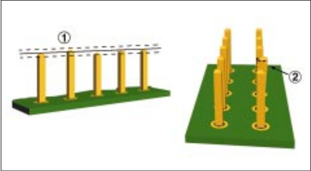
.Damaged nonfunctional lands for single and double-sided boards are acceptable if firmly attached to board in unlifted areas.


P2P1

1.Land lifted 75% of annular ring or less
2.Land with conductor
3.Land not fractured
4.Land lifted,fractured but firmly attached land with out conductor (nonfunctional)


Defect-Class1,2
Any functional annular ring which is lifted more than 75% of the width(W).

Defect-Class3
Any lifted or fractured annular rings with press fit pins.

 p2p2

1.Land fractured
2.Functional land lifted greater than 75% of annular ring
3.Landlifted


Defect-Class1,2,3
Pin is bent out of alignment.(Pin is bent off center greater than 50% pin thickness.


p3p1


Defect-Class1,2,3
Pin visibly twisted.


p3p2


Defect-Class1,2,3
Pin height is out of tolerance as to specification.

p4p1


Defect-Class1,2,3
Damaged pin as a result of handling or insertion.
Mushroomed
Bent

 p4p2


Defect-Class1,2,3
Damaged pin (exposed basis metal).

Defect-Class2,3
Burr

 p4p3

1.Burr
2.Plating missing


                                                                                    Press Fit Pins-Soldering

The term “press fit pins” is generic in nature and many types of pressure inserted pins,e.g. connector,staked,etc.,are not intended to be soldered,if soldering is required the following criteria is applicable


Target-Class1,2,3
.A 360 solder fillet is evident on the secondary side of the assembly.
.Note:Solder fillet or fill on primary side is not required.

 p5p1


p5p2

1.Bottom view
2.Side view
3.Land
4.Top view
5.PCB


Acceptable-Class1,2
Solder fillet or cover age (secondaryside) is present on two adjacent sides of the pin.


p5p3

1.Bottom view
2.Side view
3.Land
4.Top view
5.PCB


 Acceptable-Class1
Solder wicking is permitted above 2.5mm\[0.0984in] on sides of pins provided there is no solder build up which interferes with subsequent attachments to the pin.


Acceptable-Class2,3
Solder wicking on sides of pins is less than 2.5mm\[0.0984in], provided the solder does not interfere with subsequent attachments to the pin.

 p6p1


Defect-Class1,2
Solder fillet or coverage is evident on less than two adjacent
sides of the pin on the secondary side.

Defect-Class3
Solder fillet is evident on less than four sides of the pin on
the secondary side.

Defect-Class1,2,3
Solder build up interferes with subsequent attachments to the pin.

Defect-Class2,3
Solder wicking exceeds 2.5mm\[0.0984in].

 p6p2

1.Bottom view
2.Side view
3.Land
4.Top view
5.PCB


Backplanes

Acceptable-Class1,2,3
.Chip on nonmating surface of separable connector pin
.Burnish on mating surface of separable connector pin,providing that plating has not been removed.
.Chip that encroaches the mating surface of separable connector pin which will not be in the mating connector contact
wear path.


p7p1

A.Sheared/nonmating surface of connector pin
B.Coined/mating surface of connector pin


Defect-Class1,2,3
Chipped pin on mating surface of separable connector
Scratched pin that exposes nonprecious plating or base metal.
Missing plated on required areas.
Burr on pin
Cracked PCB substrate.
Pushed out barrel as indicated by copper protruding from bottom side of PCB.


p7p3

Frequently Asked S-600-OF Pick & Place Radial Component machine Questions and Answers

What components can the S-600-OF place?

The  S-600-OF  can place components ranging from 0402-??mm2 .  

Radial Leaded components 

Package range is 

What is the minimum/maximum PCB size?

 S-600-OF  can populate a 2″x2″ (50mmx50mm)/15″x18″ PCB(381mmx460mm)

Thickness range: 0.5mm-5.0mm

Weight is restricted to 3.3 lbs. maximum (completed PCB)

What is the topside/bottomside PCB clearance?

Maximum component height is o.256″(6.5mm)

Bottomside clearance is 30mm under the PCB

1. What will be assembled?

2. How much of it will be assembled?

3. How fast must it be assembled?

4. What operations must be performed?

5. In what order should those operations be completed?

6. Can the product design be adapted to accommodate automation?

7. Where are the “trouble spots” in how the product was previously assembled?

8. How well do the parts and components meet tolerances?

9. What Quality standards does the part have to meet?

10. Is there enough space for the equipment?

11. What kind of environment will the equipment be in?

12. How much money is available to spend and When?

13. Will workers need to be hired to run and maintain the equipment?

14. Will workers need to be reassigned?

15. Will the machine be located in another country?