Southern Machinery provides professional SMT peripheral equipment





Why SMT? How to EMS?
Why SMT?
Manufacturers continuously evaluate new components and systems technologies in terms of reducing size, increasing design flexibility, improving reliability and reducing cost for systems. SMT satisfies all these requirements. It can provide size reductions of over 40%, assembly cost reductions of almost 50%, and can enhances the performance of electrical circuitry [Lea, 1988].
SMT Reduces Size and weight
The increased density of components can lead to a higher functionality in the same space. This allows the system manufacturer to price differentiate his product in the market by carefully choosing his components.
- SMT components require less circuit board area and volume than their through-hole equivalent.
- Components can be mounted on both sides of boards.
- Lighter components with the same functionality can be significant in the
aerospace industry as well as portable consumer electronics.
SMT Increases Performance
- SMT offers better interconnectivity due to shorter paths, providing lower inductance and capacitance.
- SMT reduces the package propagation delay, which is the time the signal needs to move from one component to another. Typically the longest delays in the system are off-chip.
- Electromagnetic interference can be decreased by combining sensitive circuits on a single board and improving its Electromagnetic Induction (EMI) shield design.
SMT Improves Reliability
- The smaller and lighter construction of SMC’s allow them to resist shock and vibration better than their through-hole counterparts.
- The reduced number of PCBs and connectors improves overall reliability at the system level.
- However, SMT systems require careful attention to mechanical design to avoid overstressing the solder joints.
- The demanding nature of the SMT process has resulted in extensive automation and corresponding increases in product quality.
-
SMT Reduces Cost
• Bare Boards
The use of SMT, typically, results in smaller area PCBs being used due to the reduction in the size of the components being used. In general for two functionally equivalent PCBs, one utilizing surface mount and the other using conventional through hole, the larger the PCB, the more expensive it will be. Increased density on an SMT board generally requires multiple layers as well as smaller line widths and spacings to accommodate the finer pitch components and smaller hole diameters to interconnect the layers. The only time a hole is required is to carry the signal to another layer whereas with through hole components there must be a hole for each lead of each component. In some cases through hole PCB’s may require more layers because there are more larger holes which means there will be less room on the inner layers for circuit routing increasing the layer count.• Processing
Surface mount components have almost all been designed for automatic assembly. Many unusually shaped, through-hole components, called odd- formed components, which were designed for hand assembly, can now be placed automatically as well. Automated assembly of surface mount assemblies can be done using one flexible automated placement machine whereas several machines may be required for the various through hole components.
As more types of components become available in a surface mount format, correspondingly fewer components are available in through-hole configuration forcing the cost of many SMC devices down. While through-hole components can be automatically inserted, the combined equipment, floor space and processing costs are higher.
• Factory Operating
Fewer types of assembly machines are required for an SMC assembly line and they often requires less floor space. Automated SMT assembly lines are considerably more productive than PTH assembly tools. Thus throughput is raised considerably with SMT manufacturing and the cost per unit of assembly is greatly reduced.
SMT Increases Flexibility
- SMT provides a wider range of packaging possibilities than insertion mount technology.
- SMT allows for the use of both surface mount and insertion mount devices in the same assembly.
SMT Eases Handling And Storage Space Needs
Surface mount components are easy to handle due to the various storage formats in which they are shipped and presented to the pick and place machines. Tape and reel, cartridge, sticks, magazines, and matrix trays allow effective and safe handling and shipping. The storage formats have the following features:
- Large number of components per packing unit resulting in less frequent loading of the tools.
- Small amount of packing materials per component resulting in lower shipping and inventory costs.
- Protection against transport and handling damage.
- Standardization, Definite orientation of the components.
- Protection against electrostatic discharge resulting in fewer defective systems
and rework.
- Compatible with highly automated equipment.
Electronic Industry Organizations and Groups
Uniform Standards for Surface Mount Technology are still under development in the USA, Europe and Japan. Although much has been accomplished, there is still no single set of industry guidelines. However, efforts are being taken to resolve this problem. For example, there was inconsistency in the standards set by the IPC and the EIA. As this was recognized, they have joined forces to set up a council called Surface Mount Council, to coordinate the various standards between the users and the developers of these standards. These documents have a J-STD- xxx designation. Moreover, other organizations like the International Microelectronics and Packaging Society (IMAPS) are working together on the technical issues in the PCB industry. These developments are promising and should lead to a common industrial standard in the near future.
IPC- Association Connecting Electronics Industries
2215 Sanders Road Northbrook, IL 60062-6135 USA Tel: (847) 509-9700 Fax – (847) 509-9798
Internet: www.ipc.orgIn 1999, IPC changed its name from Institute of Interconnecting and Packaging Electronic Circuits to IPC. The new name is accompanied with an identity statement, Association Connecting Electronics Industries.
IPC started in 1957 as the Institute for Printed Circuits. As more electronics assembly companies became involved with the association, the name was changed to the Institute for Interconnecting and Packaging Electronic Circuits. In the 1990s, most people in the industry could not remember the name and/or didn’t agree on what the words in the name meant. In addition, the leaders from government or other business groups could not understand the name either.

How to maintain Auto Insertion and SMT machine — ESD Cleaning and Testing Procedures
Procedures and Adjustments
CAUTION
The following procedures explain how to properly clean and test an ESD surface.
Clean an ESD Surface
Do not use abrasive or highly alkaline cleaners on polycarbonate. Never scrape polycarbonate with squeegees, razor blades, or other sharp instruments. Benzene, gasoline, acetone, or carbon tetra chloride should never be used on polycarbonate. Do not clean polycarbonate in the hot sun or at elevated temperatures.
- Using a sponge or soft cloth, wash the ESD-protected surface with either a mild detergent or Windex product and lukewarm water.
- After washing, rinse with water and dry thoroughly with a chamois or moist cellulose sponge to prevent water spots.
- To protect the ESD surface after rinsing and drying, recommends applying Kleenmaster Brillianize®. This application helps to maintain the static dissipative coating and reduce the accumulation of dust.
Test Static Dissipative Covers
Periodically and after maintenance, check the machine covers to determine if the dissipative qualities of the cover have changed. The following procedure ensures that static dissipative covers are in fact dissipative.
Tooling
Surface resistance meter (such as 3M 701 Surface Resistance meter and probe).
Comments
The surface resistance should be less than 109 ohms in all areas. If the cover package is no longer dissipative, contact you Universal Instruments Corporation sales representative.
Procedure
- Clean the static dissipative covers using the Clean ESD Surface procedure to ensure the accuracy of the test.
- Using the surface resistance meter, follow the instructions provided by the manufacturer to measure the surface resistance of both the inside and outside of the covers. Measure the resistance at all four corners and at several areas in the middle of the cover. This test checks the integrity of the ESD coating.
- Connect the ground path resistance probe to the meter and chassis ground.
The path to the ground should not be higher than the surface resistance. If it is, clean the frame connections, repair loose or corroded fasteners and ground straps, and check tracks for dirt and/or corrosion.
4. Measure the ground path from the covers to the chassis ground. Take this measurement from both surfaces and all four corners of each cover.
How to improve Auto insertion machine spare parts lifetime ?
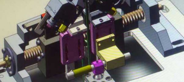
Continuity Tube Life Expectancy
Applies to tubes used in Generation 8 clinch units.
The expected life span of a Continuity Tube is dependent upon a number of factors including:
- Lead Composition
A Continuity Tube that is subjected to steel leaded components will cause more stress between the cutter, the cutter Bushing, and the continuity Tube. Expect to experience a higher wear rate on a continuity tube that is subjected to stiffer lead material than a continuity tube that is subjected to softer leaded material.
- Lead Diameter
A larger lead diameter will cause more stress between the cutter, the cutter bushing, and the continuity tube. Larger leads being cut will accelerate the wear of a Continuity Tube.
- Tooling Maintenance
Worn Tooling (cutters and cutter bushings) will cause the scrap lead to ‘tear’ instead of cut with a sharp clean cut. This ‘tear’ in the lead will accelerate continuity tube on both the metal tube and the plastic surrounding the metal tube. The tooling should be changed at recommended intervals, sooner if tearing of leads is noticed.
- Working Environment (dust, humidity, temperature, etc.)
The continuity tube should be kept as clean as possible. Dust buildup caused as a result of the cut/form process and clinching process will grind into the metal tube and the plastic surrounding the metal tube possibly causing accelerated wear of the continuity tube.
There are too many variables associated with the performance of a continuity tube to allow Universal to list it as ‘consumable tooling’ and publish an estimated life span. The greatest life span will be generated by keeping the continuity tube as clean as possible, keeping the lead length within the middle of acceptable lead length range, and changing the cutters and cutter bushings on a regular basis.
Continuity Tubes and False Insertion Errors
Proper continuity lead sense is dependent upon the relationship between:
- the continuity tube
- the cutter
- the angle of the lead being cut
- the lead length as the leads are cut.
It is important the lead is bent and touches the continuity tube before the cut takes place, making the position where the lead enters the cut and clinch assembly very important.
As the cutter moves across to the cut position, the lead begins to bend in the direction of the continuity tube. However, once the lead is pinched between the cutter and the cutter bushing, the scrap portion of the lead will no longer be pushed toward the continuity tube. At this point the scrap portion of the lead will actually be forced in the opposite direction of the continuity tube as the cutter shears through the lead.
The following scenario describes what happens if the lead length is set too short. In other words, the lead entrance to the cutter bushing set so the lead is very close the cutter bushing shear point.
By setting the lead length too short, (the lead too close to the cut point of the cutter bushing), the scrap portion of the lead will not be bent far enough to reach the continuity tube as the cutter bends the lead, resulting in a false insertion error. In other words, if the lead reaches the cut point before it has been bent far enough to touch the continuity tube, a false continuity error may occur.
On the other hand, having the lead length too long may cause accelerated wear and damage to the continuity tubes. Forcing the lead into the continuity tube with too much force will cause denting of the continuity tube and wear of the plastic insulation, resulting in premature failure and false continuity errors over time.
Cutter Stroke Speed and false Continuity Errors
The length of time necessary to drive the Cutter from the home position, to the extended ‘cut’ position, can affect continuity sensing. If the cutter speed is set too slow, the cutter air pressure is insufficient, or a mechanical assembly used in the operation of the cutter stroke binds, the cutter will not reach the component lead in the ‘window’ of time necessary for continuity to be sensed. This will result in a false continuity error. Examples of cutter stroke speed problems:
- Pneumatic flow control for the cutters not properly set
- Poor air flow from the valve to the cutter
- Binding in the mechanical linkage from the cutter piston to the cutter
- Lack of sufficient lubrication in the mechanical linkage from the cutter piston to the cutter
- Incorrectly set cutter backstroke (the starting position for the cutter)
- A torn O-ring on the cutter piston which causes a bind in the cylinder
- Lack of sufficient lubrication on the O-ring for the cutter piston
END
LED IoT Movement: How Smart Lighting is Brightening the Future & Your ROI
LED Smart Lighting.
Brightening the LED IoT Movement.

The LED IoT Smart Lighting market is projected to grow over 45% per year by 2020. This multi-billion dollar industry continues to create lighting for all markets meeting demands for efficiency, long lasting lights, and cost cutting on the manufacturing end.
Looking at how the market for the internet of things (IoT) is expanding and spreading into every industry, the notion that people can control https://zanaflexhome.com every light switch, electronic device or even plumbing fixtures while monitoring the energy usage of these items, are changing the lighting industry in monumental ways. LED is now a global movement and manufacturing companies are quickly advancing their machines to keep up with the great demand.

It is time to consider LED for your manufacturing…
[su_button url=”mailto: info@smthelp.net” background=”#00a3b3″ size=”5″]CLICK HERE for more HELP with Your LED IoT Future! [/su_button]
