Surface Mounted Technology (SMT) is one such approach that works by mounting the circuit components directly onto the printed circuit board resulting into what is called a surface mount device. This is a common replacement for the traditional soldering into holes in a circuit board since it results to tightly squeezed and versatile builds.
There are some important things to know before venturing into SMT

1.The procedure to doing the job
A specially designed printed circuit board is needed for the job. In automated placement, components to be added to the circuit board are placed onto the PCB by pick-and-place machines before the board is placed in a reflow soldering oven, which slowly and uniformly raises the board’s temperature until the thin film of solder material melts and clamps the components into place. The function of the reflow oven varies depending on the design concerns with the most common being infrared lamps, hot gas convection and use of special fluorocarbon liquids.
2.Tools needed for the job
To achieve the desired environment in SMT production, you have to use the right tools that depend on the precision of the job you do. The choice of tools, board material and ovens, you have to determine the design of your circuit before making the call. The tools used in an SMT procedure dictate the success or failure of product.
3.Advantages
The bright side of SMT assembly lies in the fact that these techniques can handler smaller components and achieve higher component density. With the option to solder onto both sides of the board and lower induction and induction at the contacts, this technique is the solution to creation of highly integrated circuits that are on high demand, as miniaturization of components becomes the order of the day.

4.Disadvantages
On the other hand, problems come with the SMT manufacturing. For instance, the techniques makes repair difficult in case the equipment needs to have some components replaced, SMT components do not work with plug in breadboards, is unsuitable for high power components like electric circuits and is not a good way of creating contacts for connectors that interface with outer world hence subject to frequent mechanical stress.
5.SMT Production does not work in all cases
It is important to know that SMT does not support all types of applications in a circuit. While the technology is right with most of the tasks that traditional soldering can address, it cannot handle some special cases. For instance, the soldering of transformers and mounting of heat sinks must be done the traditional way if at all these components has to work properly.
6.Analyze your market and learn the legislations governing the market
Before venturing into SMT manufacturing, you have to be sure that you have the demand. SMT equipment has very high capacity and requires trained personnel and engineers. You have to weigh the market to ensure that you do not invest in hardware that will lie to waste in a ware house waiting for meager contracts in on and off basis.
Finally, you must understand that there are some conventions set up by different quality management firms to ensure that equipment delivered to the market are up to standard. To remain on the safe side of the law and other regulations, ensure that your operations remain legal and top quality to maintain your reputation in the market
If you want to know more about SMT whole line ,such as picture ,video and ppt .You can contact me .
Email :quella @smthelp.net
Skype :fan19920311
PCB Assembly


48797301 board
Procedure
Symptoms of corrupted BIOS and/or Boot Block:
Steps to take:

Figure 1 EPC-1316 Board jumper pin location

Figure 2 EPC-1316 Board jumper pin numbering

Figure 3 EPC-1316 Board flash jumpers configuration
UIC, EPC-1316 Boot Sector and BIOS Corruption Procedure for Re-flash
Procedure
Symptoms of corrupted BIOS and/or Boot Block:
Steps to take:
Figure 1 EPC-1316 Board jumper pin location
Figure 2 EPC-1316 Board jumper pin numbering
Figure 3 EPC-1316 Board flash jumpers configuration


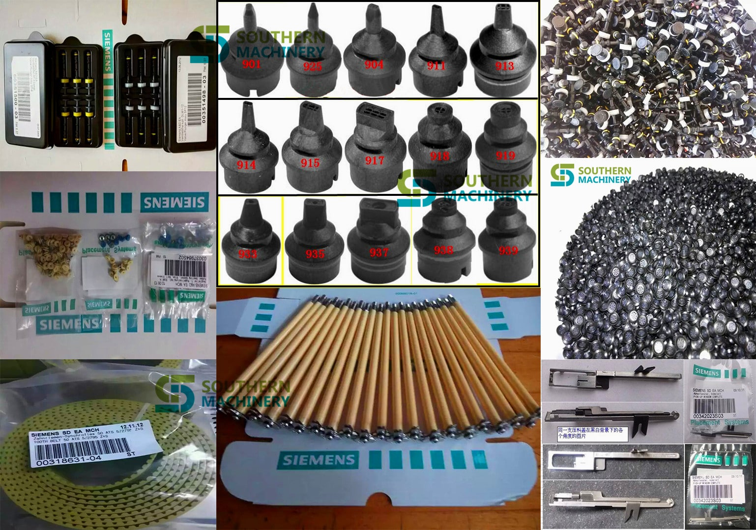
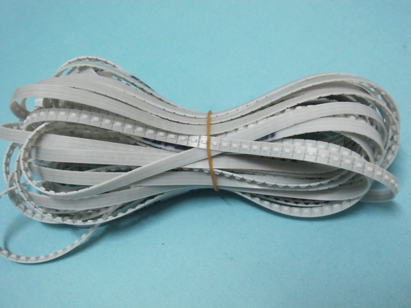
We can supply smt machine parts, smt spare parts, replacement parts for pick and place machine, Brands including FUJI, SIEMENS, PANASONIC, JUKI, YAMAHA, , etc.
Part of product list:
|
Compatible for |
Part name |
Part No. |
Usage |
|
fuji NXT H01 |
H01 Filter (with plastic BKT) |
AA1FZ01 |
Consumable parts |
|
fuji NXT H12 |
H12 Filter (with plastic BKT) |
AA19H02 |
Consumable parts |
|
fuji NXT H01 |
H01 smt filter |
XH00560 |
Consumable parts |
|
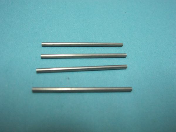
fuji |
smt pin thick pin |
ADCQK8010 |
replacement parts |
|
fuji |
smt pin thin pin |
ADCQK8010 |
replacement parts |
|
fuji XP243 |
XP243 U axis PULLEY |
AGFTR8220 |
replacement parts |
|
fuji XP243 |
XP243 U axis PULLEY |
AGFTR8230 |
replacement parts |
|
fuji |
fuji sliding block and thimble |
O0186 |
replacement parts |
|
fuji CP6 |
CP6 HOLDER |
AWPH3110 |
replacement parts |
|
fuji CP43 |
CP43 CLUTCH |
MPH0501 |
replacement parts |
|
fuji QP242 |
QP242 Filter |
H3022T |
Consumable parts |
|
fuji CP41 |
CP41 press button |
O0191 |
replacement parts |
|
fuji IP3 |
IP3 Filter |
H30215 |
Consumable parts |
|
fuji CP6 |
cylinder |
WPA5150 |
Consumable parts |
|
fuji CP7 CP8 |
smt filter |
DCPH3780 |
Consumable parts |
angela@smthelp.net

angela@smthelp.net
angela@smthelp.net
angela@smthelp.net
angela@smthelpl.com

angela@smthelp.net
angela@smthelp.net

angela@smthelp.net
angela@smthelp.net
angela@smthelp.net

angela@smthelp.net

angela@smthelp.net
angela@smthelp.net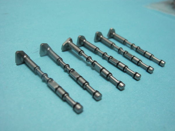
|
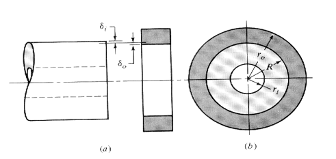
This calculates the delfection of the outer race of a bearing when it is pressed into a housing. |
|
|
|
|
|
These equations are from Shigley and Mischke “Mechanical Engineering Design” Fifth Ediion p.62-63 |
|
|
|
|
|
|
|
|
|
|
|
|
|
|
|
|
|
Bearing |
|
|
Housing |
|
|
Modulus of Elasticity of Inner component (Ei) |
30000000 |
|
Modulus of Elasticity of Outer component (Eo) |
10300000 |
|
Inner Radius of Inner Component (land radius)(ri) |
0.1705 |
|
Outer Radius of Outer Component (ro) |
0.3 |
|
Poisson’s Ratio of Inner Component (vi) |
0.292 |
|
Poission’s Ratio of Outer Component (vo) |
0.334 |
|
|
|
|
|
|
|
Radius at Press (interface) (R) |
0.1875 |
|
|
|
|
Radial Press (d) |
0.0003 |
|
|
|
|
|
|
|
|
|
|
Results |
|
|
|
|
|
Resulting Pressure (p) |
2599.55178212877 |
|
|
|
|
Increase in Housing Outer Radius (delta ro) |
0.000123796616002366 |
|
|
|
|
Decrease in Bearing Inner Radius of OD (delta ri) |
0.000176203383997634 |
|
|
|
|
|
|
|
|
|
|
|
|
|
|
|
|
|
|
|
|
|
|
|
|
|
|
|
|
|
|
|
|
|
|
|
|
|
|
|
|
|
|
|
|
|
|
|
|
|
|
|
|
|
|
|
|
|
|
|
|
|
|
|
|
|
|
|
|
|
|
|
|
|
|
|
|
|
|
|
|
|
|
|
|
|
|
|
|
|
|
|
|
|
|
|
|
|
|
|
|
|
|
|
|
|
|
|
|
|
|
|
|
Assumptions: |
|
|
|
|
|
Both members have the same length. |
|
|
|
|
|
Cross sections are uniform. |
|
|
|
|
|
Radial interference is constant around the circumference. |
|
|
|
|
UBUG Users Guide ( Debugger reference manual )
for Radysis Motion Controler
The
UBUG monitor is a stand alone software package designed to allow
evaluation and debugging of the UIMC 68EC030 based motion controller
PCB. It has the capability to load and execute user code and includes
an assembler/disassembler designed for quick program patchwork. The
monitor operates in a user interactive command driven mode signified by
the UIC> prompt. The command line entered after this prompt
determines which operation is performed.
UBUG MONITOR
TABLE OF CONTENTS
1. GENERAL INFORMATION
1.1 Description of UBUG………………….. 3
2. THE UBUG COMMAND SET
2.1 Introduction………………………… 3
2.2 Auto Null (an)……………………… 4
2.3 Assembler/Disassembler (as) ………….. 4
2.4 Block of Memory Fill (bf)…………….. 6
2.5 Block of Memory Move (bm)…………….. 6
2.6 Break Point (br)…………………….. 6
2.7 Block Search (bs)……………………. 7
2.8 Counter Test (ct)………………. 7
2.9 DAC16, ADC8 Test (dac16t)……………. 7
2.10 Data Conversion (dc)…………………. 8
2.11 Go (go)…………………………….. 8
2.12 Help (?/he/help)…………………….. 8
2.13 IO Access (io)……………….. 8
2.14 Load S-Records (lo)………………….. 9
2.15 Memory Display (md)………………….. 9
2.16 Memory Modify (mm)…………………… 10
2.17 Memory Test (mt)………………….. 10
2.18 Register Display (rd)………………… 10
2.19 Register Modify (rm)…………………. 11
2.20 Symbol Define (sd)…………………… 11
2.21 Test – Diagnostic (test)………………. 11
2.22 Transparent Mode ™………………… 12
2.23 Trace (tr)………………………….. 12
3 USING THE ONE-LINE ASSEMBLER/DISASSEMBLER
3.1 Introduction ………………………. 12
3.2 Entering and Modifying Source Program …. 12
3.3 Entering a Source Line……………….. 13
3.4 Entering a Change of Flow Instr ……… 14
3.5 Entering Register Lists ……………… 15
3.6 Entering Floating Point Immediate Data … 16
3.7 Entering MMU Instructions ……………. 17
1. GENERAL INFORMATION
1.1 DESCRIPTION OF UBUG
The
UBUG monitor is a stand alone software package designed to allow
evaluation and debugging of the UIMC 68EC030 based motion controller
PCB. It has the capability to load and execute user code and includes
an assembler/disassembler designed for quick program patchwork. The
monitor operates in a user interactive command driven mode signified by
the UIC> prompt. The command line entered after this prompt
determines which operation is performed.
2. THE UBUG COMMAND SET
2.1 INTRODUCTION
This
section explains the UBUG monitor commands and their associated syntax.
Table 2.1 summarizes the available commands and shows the section where
the command is explained in greater detail.
|
TABLE 2.1 UBUG MONITOR COMMANDS |
||
|
Command/Mnemonic |
Name |
Section |
|
an |
Auto Null |
2.2 |
|
as |
Assembler/Disassembler |
2.3 |
|
bf |
Block of Memory Fill |
2.4 |
|
bm |
Block of Memory Move |
2.5 |
|
br |
Breakpoint |
2.6 |
|
bs |
Block of Memory Search |
2.7 |
|
ct |
Counter Test |
2.8 |
|
dac16t |
DAC16, ADC8 Test |
2.9 |
|
dc |
Data Conversion |
2.10. |
|
go |
Go |
2.11 |
|
?/he/help |
Help |
2.12 |
|
io |
IO Access |
2.13 |
|
lo |
Load S-Records |
2.14 |
|
md |
Memory Display |
2.15 |
|
mm |
Memory Modify |
2.16 |
|
mt |
Memory Test |
2.17 |
|
rd |
Register Display |
2.18 |
|
rm |
Register Modify |
2.19 |
|
sd |
Symbol Define |
2.20. |
|
test |
Test – Diagnostic |
2.21 |
|
tm |
Transparent Mode |
2.22 |
|
tr |
Trace |
2.23 |
The command line is composed of:
<COMMAND IDENTIFIER>: specifies which command (ex. br )
<SP>: at least one space
OPTION LIST: an option may use delimiter(-) with options if non-default
options are allowed and are being used. (ex.
[<-r>])
<SP>: at least one space
ARGUMENTS: any required arguments specified by the command separated
by commas/spaces as shown in the command
description. (ex. <ADDR,ADDR>)
where “<>” enclose symbols that are required on the command line
and “[<>]” enclose symbols that are optional on the command
line. Note, in the above examples the -r option was an example of an
optional symbol and that the ADDR fields are requirements on the
command line. The options available with a given command are fully
explained in the section that describes that command. The monitor is
not case sensitive to input from the terminal. All input from the
terminal is converted to lower case before being used internally (except
text following a text delimiter; See TEXT below). The arguments of a
given command are described using the following symbols:
<EXP>: An expression can be any numerical expression which may
be evaluated using only the arithmetic + and – operators.
Ex. 1000
Ex. 1+3
Note: Numbers may be preceded with a base designator if the default
(hexadecimal) is not desired. These designators are shown below in Table
2.2:
TABLE 2.2 BASE DESIGNATORS
|
Base |
Designator |
|
Hexadecimal |
$ |
|
Decimal |
& |
|
Octal |
@ |
|
Binary |
% |
<ADDR>: Address field is any valid expression. Note: This
address field should not be confused with the source and
destination addresses required using the Assembler/Disassembler.
<COUNT>: Count field is any valid expression preceded by a COUNTDEL (count delimiter ie. “:”)
Ex. :100
<RANGE>: A range of memory locations denoted by either ADDR,ADDR or ADDR:COUNT.
Ex. 0,100
Ex. 0:50
<TEXT>: An ASCII string of up to 255 characters preceded by a TEXTDEL (text delimiter i.e.. “;”)
Ex. ;sample text
<SIZE>: Can be either:
byte (8 bit) ====> -b
word (16 bit ) ====> -w
long (32 bit) ====> -l
**Note: ====> stands for “is represented by” or “returns”
<DATA>: Data can be any valid expression.
<MASK>: A mask may be any expression. After evaluating the
expression 0’s represent don’t cares. A mask is sometimes
used to qualify
<DATA>. See section 2.6 for an example of usage.
2.2 AUTO NULL
an <AXIS>
The auto null function performs a nulling of the zero offset of the 16bit DAC of the axis specified.
Examples of use:
an 1 ( nulls axis one )
2.3 ASSEMBLER/DISASSEMBLER
as <ADDR>
The assembler/disassembler is invoked at the address given and
disassembles the object code at that location. Use of the
Assembler/Disassembler is fully described in chapter 3.
2.4 BLOCK OF MEMORY FILL
bf [<SIZE>] <RANGE> <DATA>
The block fill command fills the specified range of memory with the
data listed. If the size option is not specified the default size used
is word. If a multiple of the <SIZE> of <DATA> does not
fit evenly in the <RANGE> the command leaves the last partial
word or long word unchanged.
Examples of use:
bf 100,110 &10
bf 100:8 &10
bf -w 100:8 a
bf -l 100,110 a000a
**Note: All of these examples perform the same memory fill.
(ie. $00000100: $000a $000a $000a $000a $000a $000a
$0000010C: $000a $000a $0000 $0000 $0000 $0000 )
2.5 BLOCK OF MEMORY MOVE
bm [<SIZE>] <RANGE> <ADDR>
The block move command allows the user to copy segments of memory to
different locations in memory. The execution of this command does not
destroy the original version unless the location moved to <ADDR>
is within the range <RANGE> of the code being copied. The size
option is only available when range is described as
<ADDR>:<COUNT> . If range is being described with the
<ADDR>,<ADDR> mode the size defaults to byte. The size
field represents the size transfer that is used to accomplish the memory
move.
Examples of use:
bm 1000,2000 10000
bm 1000:800 10000
bm -l 1000:400 10000 **Note: This variation executes the fastest
**Note: All of these examples perform the same memory move.
2.6 BREAKPOINT
br
br <ADDR>
br <ADDR> <:COUNT>
br -r [<ADDR>]
br -r
The breakpoint command allows the user to list, insert or delete
breakpoints in the target code. This allows the user to stop executing a
program and return to the monitor environment when the specified
<ADDR> is prefetched. The different uses of this command are
summarized below:
br list all known breakpoints
br <ADDR> insert a breakpoint at this address
br <ADDR> <:COUNT> insert a breakpoint at this address, however, return to the monitor environment only after encountering the
breakpoint <COUNT> number of times.
br -r [<ADDR>] remove the breakpoint at this address
br -r remove all breakpoints
2.7 BLOCK SEARCH
bs [<SIZE>] <RANGE> <DATA>
bs [<SIZE>] <RANGE> <DATA> <MASK>
The block search command allows the user to find a specific pattern
within memory. The search area may extend beyond the <RANGE>
specified if a pattern is started within <RANGE>. There are two
primary types of searches:
bs [<SIZE>] <RANGE> <DATA> searches the range for an exact match of <DATA>.
bs [<SIZE>] <RANGE> <DATA> <MASK> searches
the range for any pattern that matches <DATA>
where there is a “1” in the binary representation of the
mask.
Ex. With memory at location $100 as shown below, executing
“bs 100,118 $1234 $ffbf” ====>
Starting address: $00000100
Ending address: $00000117
Found at: $00000110:$1234
Found at: $00000114:$1274
Memory for the example above:
$00000100: $0000 $0000 $0000 $0000 $0000 $0000
$0000010C: $0000 $0000 $1234 $0000 $1274 $0000
2.8 COUNTER TEST
ct
The counter test command performs a diagnostic test on the 4 axis counters and pass/fail information is returned.
2.9 DAC16, DAC8 TEST
dac16t <AXIS #>
The dac16t command performs a diagnostic test of the 16bit DAC and the
8 bit ADC for the axis specified by using the diagnostic wrap around
capability of the UIMC. Pass/fail information is returned.
2.10 DATA CONVERSION
dc <EXP>
The data conversion command allows the user to evaluate an input
expression and determine its hexadecimal and decimal equivalent.
Examples of use:
**NOTE: The following symbols have been defined earlier in order
to be used in the examples below:
Ex 1. uses /start= 0
Ex 2. uses /start= – $18
Ex 3. uses /finish= 10000 and /start=$10000
(see section 2.17 )
Ex. 1 dc $17+/start ====> $17 = &23
Ex. 2 dc $17+/start ====> UNSIGNED : $FFFFFFFF =
&4294967295 SIGNED
: -$1 = -&1
Ex. 3 dc $/finish-/start ====> $10000 = 65536
2.11 GO go [<ADDR>]
The go command allows the user to execute target programs. If an
address is not specified on the command line then the current PC value
is used. This value is either:
1.) the initialized PC value if no target code has been run.
2.) the last value of the PC used in executing target code.
3.) the value placed into the PC register by a RM command (Register Modify see section 2.16 ).
If an address is included on the command line then the PC is modified
to be the specified addr. and execution begins at this address. In
both cases, the register state that the microprocessor is initialized
to, before executing the target code at this location, can be viewed by
executing a rd command (See section 2.15).
2.12 HELP
? [<symbol>]
he [<symbol>]
help [<symbol>]
The help command allows the user to view a list of allowable commands
and the syntax associated with them. Symbols used to describe the
command usage can be looked up also.
Examples of use:
?,he or help ====> return a complete listing of all commands with usage
? as ====> AS <addr> help addr ====> <number>
he number ====> <hex> || <dec> || <oct> || <bin> || <symbol>
** Note: <number> may also be an expression
2.13 IO ACCESS
io
The IO access command allows the user to access various options of the
UIMC motion controller. Upon issue of the IO command the user will be
presented with the following list of choices:
I/O Interface Menu:
i – View Inputs ( Debugger displays current state of the digital inputs)
o – Modify Outputs ( Debugger allows user to modify outputs)
c – Modify Counters ( Debugger displays current state of counters and allows user to modify the contents )
r – Modify Relays ( Debugger allows user to modify the state of the relays )
x – Modify 16bit DACs ( Debugger allows user to modify the 16bit DAC outputs )
y – Modify 8bit DACs ( Debugger allows user to modify the 8bit DAC
outputs ) z – View 8bit ADCs ( Debugger displays current state of
ADCs )
After selection of one of the above the user will be prompted appropriately.
2.14 LOAD S-RECORD
lo [<port>] [<OFFSET>] ;<TEXT>
The load command allows the user to download S-Records from the host
system. If an offset is present on the command line then the target
address is the offset added to the address determined by the S-Record.
In normal mode the command sends the <TEXT> beyond the “;” to the
HOST. It then expects the HOST to begin sending S-Records to the
terminal. If the ‘t’ option is used no ; is necessary and the debugger
expects the terminal to begin sending an S-Record.
Examples of use:
lo ;cat ubug.mx
**Note: The “cat” command is a UNIX command that concatenates
and then prints the specified files using standard output.
This effectively sends the contents of the file to the terminal. The
monitor then loads the contents of the S-Records in the file to
the addresses determined by the S-Records via the Host port.
.
lo a0000 ;cat ubug.mx
**Note: This command downloads the same S-Record file used in
the first example except that it is down loaded into memory at the
address determined by the S-Record + $a0000 (i.e.. the offset is
added in).
lo t
**Note: This command uses ‘t’ for terminal for the S-Record load port.
2.15 MEMORY DISPLAY
md [<SIZE>] <addr>
md [<SIZE>] <RANGE>
md -di <addr>
The memory display command allows the user to view memory. The size
used to display the memory is determined by the size option. If no
option is used the default is word. If the range exceeds the screen
capacity, output to the screen is suspended until any key is pressed.
Examples of use:
md -l 100,110
md -l 100:4
md 100:8
md -di 100
**Note: This command begins to disassemble the memory at
this location.
2.16 MEMORY MODIFY
mm [<SIZE>] [<verify>] <ADDR>
mm <CONTROL>
The memory modify command allows the user to view and modify memory.
The size used to display the memory is determined by the size option.
The size default is word. The write only option is determined by the
verify option. The default is read/write and an ‘n’ is used for write
only. Memory is displayed beginning at the address specified followed
by a ‘?’ prompt. The user may type in an <exp> to replace that
memory value or hit return to view the next memory value. To exit the
command, type “. <cr>” (period <carriage return>). Other
available <CONTROL> characters are summarized below in Table 2.3:
TABLE 2.3 CONTROL CHARACTERS
Control Character Designator
– <EXP> backup <EXP> memory locations
+ <EXP> advance ” ” “
= <NUMBER> do not advance Will not advance to next memory location
Examples of use:
mm -l 100 ====> $00000100 $00000000 ?
mm 100 ====> $00000100 $0000 ?
(i.e.. uses the default “word” size)
mm n 100 ====> $00000100 ?
(i.e.. does not read from location)
2.17 MEMORY TEST
mt <start> <finish>
The memory test performs a bit by bit memory test on the range of RAM specified and pass/fail information is returned.
2.18 REGISTER DISPLAY
rd
rd -f Note: Coprocessor registers displayed if present
The register display command allows the user to view the contents of the registers of the mpu/fpu.
2.19 REGISTER MODIFY
rm [<REGISTER> [<New Value>]]
The RM command allows the user to the modify the contents of the registers of the mpu.
Examples of use:
To change the PC value:
rm pc 3000 ====> changes the PC value to 3000
or
rm ====> Which register?
pc ====> PC=00004000NEW VALUE?
3000 ====> changes the PC value to 3000
or
rm pc ====> PC=00004000NEW VALUE?
3000 ====> changes the PC value to 3000
2.20 SYMBOL DEFINE
sd [<SYMBOL> <EXP>]
sd -r <SYMBOL>
The symbol define command allows the user to define symbols. These
symbols can then be used within expressions. Using a symbol in an
expression results in the symbol being substituted with the expression
that was used to define it. Once defined, the symbol is available
until the monitor is reset. If a symbol is defined multiple times the
monitor uses the first definition.
Examples of use:
sd ====> lists which symbols are already known
sd /reset 10000 ====> defines /reset to be $10000 whenever it is
used in an expression. sd /start -$18 ====> defines
/start to be -$18 whenever it is used in an expression. sd -r
/start ====> removes the first definition of /start from the
list
**NOTE: Symbols that have been defined using the sd command
can be used in any expressions. An example of this is to use a
symbol defined to enter source code while in the
assembler (i.e.. bsr /startsub after defining /startsub).
2.21 TEST – DIAGNOSTIC
test [<LOOP #>]
The test command initiates a series of diagnostic test consisting of
an auto null function, counter test, RAM test, and DAC16/ADC8 test and
returns pass/fail information. The number of times the diagnostic test
are performed is determined by the loop # specified. If no loop # is
specified the command cycles infinitely.
2.22 TRANSPARENT MODE
tm
The transparent mode command places the user into transparent mode by
establishing a software connection between the HOST and TERMINAL.
Transparent mode preempts normal communication between the TERMINAL and
the debugger. While in this mode all keyboard input is relayed directly
to the HOST. HOST responses, in turn, are returned to the screen.
Typing a CTRL A returns the user to the monitor environment.
2.23 TRACE
tr [<ADDR>][<COUNT>]
The trace command allows the user to trace though target code and
observe the registers after executing the command line. If count is
specified then the microprocessor executes <COUNT> number of
instructions before returning to the monitor environment. Trace begins
from the <ADDR> listed on the command line or from the current PC
if an <ADDR> is not included. The trace instruction can be
continued by hitting a carriage return. To exit, a “.” must be entered.
Examples of use:
tr ====> traces 1 instruction from the current PC
tr :10 ====> executes 10 instructions past the current PC then returns to
the monitor environment
tr 1000====> traces 1 instruction starting at $1000
3.0 USING THE ONE-LINE ASSEMBLER/DISASSEMBLER
3.1 INTRODUCTION
Included in the UBUG monitor is an assembler/disassembler command
which can be executed as detailed in the previous section. This
assembler/disassembler allows the user to modify target code. Each
source line that is typed in by the user is entered into memory at the
displayed address. This line is then disassembled so that the user can
verify the actual code entered into memory. If no change is desired a
<CR> moves the user to the next opcode in memory.
CAUTION: This assembler/disassembler does not insert code into the
source program; it merely overwrites memory at that location. As a
result, a program patch that requires code insertion can be accomplished
by first Block Moving code to free up an insertion area and then
inserting into that area.
3.2 ENTERING AND MODIFYING SOURCE PROGRAM
In order to enter and modify source code, the as command should be
executed as detailed in section 2.2 (i.e.. as <ADDR>). This
places the user into the Assembler/Disassembler routine.
Table 3.1 summarizes the commands that can be executed within this routine:
TABLE 3.1 ASSEMBLER/DISASSEMBLER SUB COMMANDS
Command Designator
BACKUP <EXP> – <EXP>
ADVANCE <EXP> + <EXP>
FINISH .
HELP ?
STEP PAST carriage return
DEFINE CONSTANT DC #<EXP>
**Note: Executing a ‘?’ while in the assembler/disassembler returns
the DEVICE that the assembler/disassembler is supporting.
3.3 ENTERING A SOURCE LINE
After executing an as <ADDR> command, the assembler/disassembler
returns with the disassembly of the code found at that location. At
this time the user may execute an assembler command shown in section 3.2
or type in the source line that is to replace the displayed source
code. While entering source the standard MOTOROLA effective addressing
modes are used. These modes are summarized below in Table 3.2:
TABLE 3.2 ASSEMBLER/DISASSEMBLER EFFECTIVE ADDRESSING MODES
Effective Addressing Mode Syntax
Register Direct Dn
Address register direct An
Address register indirect (An)
Address register indirect with Postincrement (An)+
Address register indirect with Predecrement -(An)
Address register indirect with Displacement (d16,An)
Address register indirect with Index (d8) (d8,An,Xn.SIZE*SCALE)
Address register indirect with Index (base disp) (bd,An,Xn.SIZE*SCALE)
Memory indirect Post-indexed ([bd,An],Xn.SIZE*SCALE,od)
Memory indirect Pre-indexed ([bd,An,Xn.SIZE*SCALE],od)
PC indirect with displacement (d16,PC)
PC indirect with index (d8) (d8,PC,Xn.SIZE*SCALE)
PC indirect with index (bd) (bd,PC,Xn.SIZE*SCALE)
PC memory indirect Post-indexed ([bd,PC],Xn.SIZE*SCALE,od)
PC memory indirect Pre-indexed
([bd,PC,Xn.SIZE*SCALE],od) Absolute Short Address
(xxx).W
Absolute Long Address (xxx).L
Absolute Address xxx optimizes (bwl)
Immediate Data #xxx
While using the POST or PRE indexed modes, fields may be skipped by using a comma. An example is shown below:
Ex. andi #12,([,],,) ====> andi.b #$12,([$0,ZA0],ZD0.W*1,$0)
Other examples of source lines are shown below:
Ex. ori.l #12,(a1) ====> ori.l #$12,(a1)
Ex. addq #1,(a1) ====> addq.b #$1,(a1)
There are only limited error screening abilities included within the monitor. Examples of this are shown below:
Ex. jmp (123).w ====> jmp ($123).W
**Note: When executed results in a bus error.
Ex. bsr (123) ====>
ERROR 10:illegal change of flow ===> bsr (123)
Note: The bsr instruction does check for illegal
changes of flow.
NOTE: Flow may not be changed to an odd addr.
Upper digits of data are NOT truncated when a mismatch between size
and immediate data is found if the byte or word size option was
specifically entered. If the long size option is specified and data
exceeds this range then upper digits ARE truncated.
Ex. addi.b #12345678,(a1) ====>
ERROR 11:immediate data/size option error ===> addi.b #12345678,(a1)
Ex. addi.l #123456789,(a1) ====> addi.l #$23456789,(a1)
Ex. addi #123456789,(a1) ====> addi.l #$23456789,(a1)
(defaults to the long option)
truncated————–^
Upper digits of data are truncated on commands that have a limited
field in the opword to store the immediate data. Examples of this are
shown below.
Ex. addq #10,(d0) =====> addq.b #$0,(d0)
Ex. trap #10 =====> trap #$0 input is hex default
Ex. trap #&10 =====> trap #$A
3.4 ENTERING CHANGE OF FLOW INSTRUCTIONS
Since the assembler/disassembler does not use labels, all instructions
that use <label> as an effective addressing mode must have their
displacement determined. If initially unknown, space for this
displacement must be reserved and then the user needs to come back and
enter the displacement. Once the displacement has been determined it
may be entered as shown in the following example:
Ex. In this example the location of the target instruction of a branch
is known to be $100000 and a BRA is needed at location 0. After
executing “AS 0” and obtaining the disassembly found at 0 the user
could type:
BRA 100000 or BRA (100000) or BRA.l #ffffe
The absolute addressing mode can be used if the target address of a
branch is known (as in the first 2 examples) or the displacement (last
example) can be entered using the immediate data addressing mode.
CAUTION: In some instances unexpected results can occur while using
change of flow statements. These instances are summarized below
with examples.
Ex.
1 If the degenerate case of a branch statement is used (i.e..
attempting to use a short branch to branch to the following instruction)
the assembler mistakenly assembles this .b option. However, since the
displacement is zero this is a .w opcode and the disassembler correctly
displays this fact to the user.
$00004000 nop ? bra.b ====> results in an INCORRECT assembly
Ex. 2 If the user attempts to force a particular size branch
statement and the actual branch requires a greater displacement than was
reserved then the assembler prints an error message: “ERR0R 16: OUT OF
DISPLACEMENT RANGE” .
$00004000 nop ?bra.w (100000)
One
way to assure this does not occur is to not enter a size option. This
allows the assembler to choose the correct size for the displacement.
3.5 ENTERING REGISTERS and REGISTER LISTS
The move multiple register instruction (movem) uses a register list as
an effective address. This list may be entered in the following
method:
Ex. a0 ====> single address register
d3 ====> single data register
a0-a3 ====> series of registers
a0-a3/a7 ====> combination of previous examples
a0-a7/d0-d7 ====> all of the registers
If coprocessor support is specified then the floating point registers
can be entered as shown below:
Ex. fp0 ====> single floating point register
fp0-fp2 ====> series of registers
fp0-fp3/fp7 ====> combination of previous examples
Many of the commands require the entering of registers other than data
or address registers. Tables 3.3 show listings of the registers that
are used and the abbreviations accepted by the assembler:
TABLE 3.3 68030 REGISTERS ( MMU Registers not availiable on 68EC030 )
Name Syntax
User Stack Pointer USP
Status Register SR
Condition Code Register CCR
Program Counter PC
Master Stack Pointer MSP
Interrupt Stack Pointer ISP
Vector Break Register VBR
Source Function Code Register SFC
Destination Function Code Register DFC
Cache Control Register CACR
Cache Address Register CAAR
CPU Root Pointer Register CRP
Supervisor Root Pointer Register SRP
Translation Control Register TC
Transparent Translation Register 0 TT0
Transparent Translation Register 1 TT1
MMU Status Register PSR
TABLE 3.4 FLOATING POINT REGISTERS ( Available if coprocessor is present )
Name Syntax
Floating Point Control Register FPCR
Floating Point Status Register FPSR
Floating Point Inst. Address Register FPIAR
Floating Point Data Register FP0-FP7
3.6 ENTERING/EVALUATING FLOATING POINT IMMEDIATE DATA
Floating point immediate data must be entered using a decimal point
with at least one (1) digit in front of the decimal place (even if it
is a ‘0’). Ex. 0.0012. Since the C compiler used was not based on the
draft proposed version of ANSI C the software is incapable of
performing the ‘assembling’ of extended immediate data to extended
precision. The monitor makes the correct conversion up to double
precision and places this result in an extended format. If the
compiler that is being used does conform to allowing a ‘long double’
type then changing the type of the variable ‘weight’ in the allowed
routine (in the asm68.c file) from double to long double should provide
the added precision. Examples of floating point immediate data shown
below:
Ex. fmove.s #5.0,fp0 ====> fmove.s 1_400000_E_2,FP0
The format on the disassembly is integer part_fraction
field_E_exponent field, where the fraction bits represent weighting of
1/2 ,1/4,….etc. from the left to the right. The exponent bits
represent the unbiased power that 2 should be raised to. A conversion to
decimal can be accomplished by evaluating:
integer + evaluated fraction x 2^exponent field
In the above example this equates to:
(1 + .25) x 2^2 = 5.0
NOTE: The monitor uses the round toward zero rounding mode in the assembler when assembling floating point immediate data.
3.7 ENTERING MMU INSTRUCTIONS ( Not available on the 68EC030 )
MMU instruction should NOT be entered with a size descriptor. The assembler defaults to the correct size.
Ex. pmove (a0),tt1 ;asssembles
pmove.l (a0),tt1 ;does not assemble even though the operation
;is a long operation.
Axial Products Competitive Analysis
|
Competitor |
Location |
Key Weaknesses |
Key Strengths |
Comments |
|
TDK (Rank 2) |
Japan/U.S. |
No Axial experience No previous Axial machines in product mix, offering only a SH VCD (no Sequencer, DH, etc.) Axial product offering is VERY similar to Dynapert V12000. Possible patent infringements on Dynapert design. Support infrastructure is inferior to UIC’s. |
Low price machines Field proven reliability of Radial Inserter Large multi-national installed base for Radial Inserter Japanese firm, thus strong JMA loyalty Asian company, thus understands Asian business needs Operates in Microsoft Windows interface, which provides immediate productivity feedback Financially sound and stable |
Offer a SH VCD – Avisert AC-7 |
TDK Competitive Summary
|
|
AC-7 Avisert Features: · Board offset correction · Insertion hole correction · Ammo or reel input packaging · Push button control panel · Microsoft Windows interface · Intelligent operator message feedback · Servo driven cam operated insertion head · Servo motor driven rotary table · Available Options: – Pass through capability – Throughput optimizer – Flexible work board holder – Touch screen – Pattern repeat – Multi tier security software – Optical safety device – Integrated machine enclosure |
Key Sell Against Points:
Universal offers a complete Axial product line; Single Head, Dual Head, VCD Sequencer and Sequencers while TDK offers a single Axial machine.
Universal completes the IM product offering with Radials and Special Products which include Eyelet and Pin Inserting Machines, and 3-Span Radials.
We offer optional Universal board handling on most models.
Universal offers a superior training, service and support infrastructure.
We offer industry leading cost per insertion and the highest throughput per square foot of floor space.
UIC Strengths and Proof Points:
|
UIC Strengths |
Benefit |
For the Customer: |
|
Machine designs allow flexibility in the production environment. |
Universal offers a complete IM product line of Axial inserters, Sequencers and combination machines, as well as Radial product offerings. Universal board handling is optional for machine integration. |
Discuss customer need for factory integration. Possible future need for increased automation. |
|
High value for the price, and fastest inserters in the industry. |
Dual Head machines provide the highest throughput in the industry, 32,000 cph, a cost effective approach for high volume applications. |
Ask the customer to compare cost per insertion. |
|
Superior service, support and training. |
Excellent investment protection. UIC is a respected and secure provider of insertion equipment. Pre and post sale assistance with specific applications and systems integration. |
Ask the customer to compare UIC’s support infrastructure (tech. specialists, spare parts, FE response time) to Panasonic. Also discuss unique value benefits – Uptime 100 and Tech Advisor. |
TDK Strengths and Counter Points:
|
Competitor Strength |
The Facts |
For the Customer: |
|
Perceived high throughput (16,000 CPH). |
The throughput Nepcon Tokyo 觀appeared closer to 10,000 CPH. Noisy. |
Demonstrate UIC’s commitment to reducing customer costs by: 1. Comparing cost per insertion. |
|
Single insertion head provides better stability and less maintenance and setup. |
Dual head machine is the highest throughput inserter in the industry with exceptional reliability and insertion performance. Single head machine offers competitive cost per insertion with all the other values of UIC. |
Demonstrate UIC commitment to customer support with: 1. Service and support, including PM schedules and maintenance manuals. 2. Uptime 100 program. 3. Tech Advisor. 4. Superior training program. |
|
Priced competitively in the 80K – 106K range. |
Targeting existing Dynapert accounts where support requirements are minimal. |
Demonstrate UIC’s commitment to reducing customer costs by: 1. Comparing cost per insertion. |
|
Financial backing from a major IM provider. |
Very similar to Dynapert V12000 machine Possible patent infringements on Dynapert design. Not a complete product line, no complementary Sequencer available to date or board handling. May not have devoted TDK backing for service and support. |
Determine if customer is will to obtain investment protection: 1. From a supplier that may not remain in business due to legal problems. 2. Has revived very old designs. 3. Discuss Broome Engineering products for low cost entry and their ability to allow trade-up. |
Appendix – Reference Accounts and Testimonials:
|
Account Name |
Salesman to contact |
Comments |
|
AT&T Monterey, Mexico |
Michael Lewis |
TDK offered AT&T accepted an all expenses paid trip to Boston to evaluate the AC-7 but still prefers the UIC Dual Head machines. |