0201 assembly, from difficult to conventional placement

0201 assembly, from difficult to conventional placement

This article explains and discusses the guiding principles governing 0201 placement in both high-volume and high-mix assembly operations.

By Ming Gan,   ming@smthelp.net

Although generally considered to be a relatively recent development, printed circuit boards (PCBs) have been available since the early 1950s. Since then, the demand for smaller, lighter, and faster electronic products has driven electronic components, PCB, and assembly equipment technology toward SMT.
The earliest general acceptance of SMT occurred in the early 1980s, when machines such as the Dynapert MPS-500 and FUJI CP-2 entered the market. At that time, 1206 (3216) resistors and capacitors were the most popular placement components. However, in one or two years, 1206 gave way to 0805 (2125) as the most common component package for SMT placement.
During this time, both machines and components evolved rapidly. As the machine became faster and more flexible, the 0603 (1608) component began to evolve. At this point, many assembly machine manufacturers went back to the R&D, research and development lab to re-evaluate the technology used to accommodate these newer, smaller components. Higher resolution cameras and smaller vacuum nozzles are among the variations that these components bring to the assembly equipment.
The emergence of 0402 (1608) packaging poses further challenges in all aspects of PCB assembly. In terms of machine development, vacuum nozzles have become smaller and more fragile. A new focus is placed on the component’s feeder, which acts as a unit for improvement, giving the machine more accurate parts.
With the advent of 0402 components, process challenges have increased to those that need to be addressed for successful component placement. Solder paste printing becomes even more critical – stencil thickness and solder paste mesh are increasingly important process considerations. The technology required for such placement also involves significant new costs.
The combination of these factors creates a new form of packaging that is the slowest to adopt in the history of the electronics industry. In total, for almost five years, 0402 packaging was widely accepted in the industry – and many assembly plants today never put a 0402 sheet.
Now, I entered 0201.
Over the past year and a half, 0201 placement has been a key topic of discussion throughout the industry. Due to the size, weight and power consumption requirements, many OEM board assemblers need to incorporate even smaller components and technologies into their products. Contract manufacturers (CM, contract manufacturer) must also have new technologies to keep the assembly process up to date and provide customers with a complete range of services. For machine builders, the challenge is to develop more resistant to obsolete assembly equipment in an era of dynamic technological change.

0201 placement challenge
The placement of the 0201 component is more challenging than the component intervention in front of it. The main reason is that the 0201 package is approximately one-third of the corresponding 0402 size.
The previously acceptable machine placement accuracy immediately became a limitation of the introduction of 0201. In addition, the traditional industrial tapeding specification allows for too much movement for reliable 0201 placement, and the level of process control must be increased to make the 0201 placement a production reality.
Although these obstacles are very large, they are far from insurmountable. Of course, they need all the determination, because the technology necessary for the 0201 placement requires a lot of money and top management’s promise of research and development (R&D).

The key to reliable 0201 placement
At FUJI, the aggressive R&D program has produced the ability to make all circuit assembly machines compatible with 0201 at 100% speed, with a minimum suction reliability of 99.90%, a target suction reliability of 99.95%, and minimal placement reliability. It is 99.99%. In the beginning, every aspect of the design was evaluated for its ability to work on a complete 0201 program, and the combination of single elements of closely related machine component parameters proved critical to success. These parameters include:

Figure 1 Component feeder table. The R&D program concluded that the ability to precisely position the carriage table – and make minimal adjustments to compensate for the inaccuracy of the tape – is a key factor in achieving component pickup reliability above 99.95%.

To achieve this, the feeder table must be precision machined to ensure repeatable positioning of the individual feeders and combined with a high-resolution semi-closed-cycle servo system using a two-track linear moving guide. This design allows for minor adjustments – based on the results of the suction accuracy as judged by the vision system. This ensures that the component is as close as possible to the center.
Component feeder. The feeder must be manufactured to extremely tight tolerances to ensure repeatability of the suction position, regardless of component height and a large number of possible component positions. The mechanism used to position and lock the feeder in position must be durable and precise, yet be user friendly. In addition, the materials used to make the feeder must be high in strength and light in weight to allow for ergonomic operation while ensuring precise, repeatable delivery of the carrier tape.
The feeder drives the sprocket. The drive sprocket plays a key role in the ability of the machine to position the component tape. The shape, taper and length of the drive sprocket teeth significantly affect the ability of the feeder to position the tape. Other factors have also been investigated, such as the diameter of the drive sprocket and the number of belts in contact with the sprocket. Changes to the basic sprocket design resulted in improved positioning accuracy, with earlier designs increasing by 20% in the X direction and 50% in the Y direction.


Figure 2 sucks the head. After properly feeding the component, the next step is to draw the component onto the vacuum nozzle and bring it to the board. Vacuum nozzles are compliant to absorb shock during pick-and-place components, compensate for small variations in solder paste height, and reduce the risk of component breakage. For these reasons, the nozzle must be able to move within its fixture.


Material selection, material hardness, machining tolerances, and thermal characteristics must all be understood to construct a reliable suction head. The nozzle must move freely within its holder without sacrificing accuracy (Figure 1).
The nozzle shaft is assembled. The nozzle shaft is also a key design element – eliminating overdrive by keeping the entire nozzle in direct alignment with the shaft assembly. Overpressure is caused by the inertia generated when the head is moved up and down. If the nozzle and the shaft are not in a straight line, there is a little whip – or overpressure. Overpressure causes a change in positioning accuracy, which is determined by the speed of movement, the weight of the nozzle, and the weight of the component. By eliminating overpressure, direct alignment reduces the number of negative factors associated with component pick-and-place placement (Figure 2).
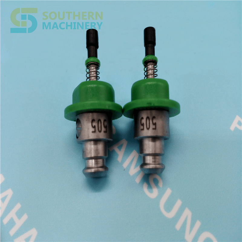
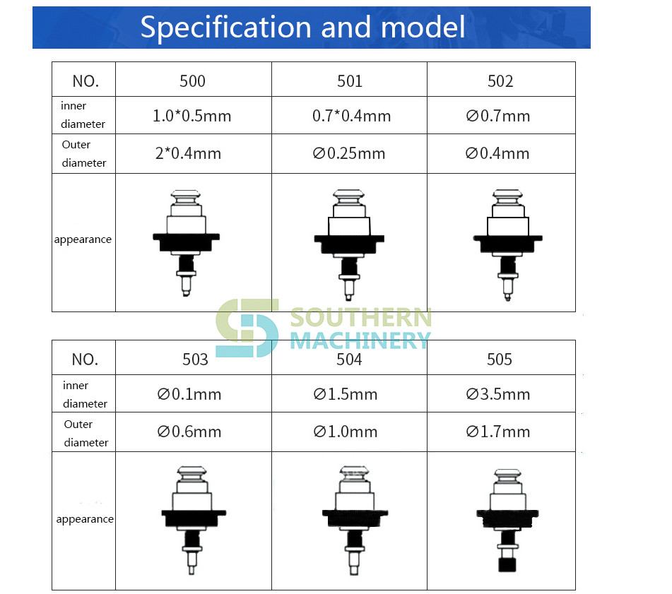
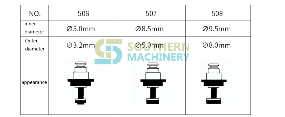
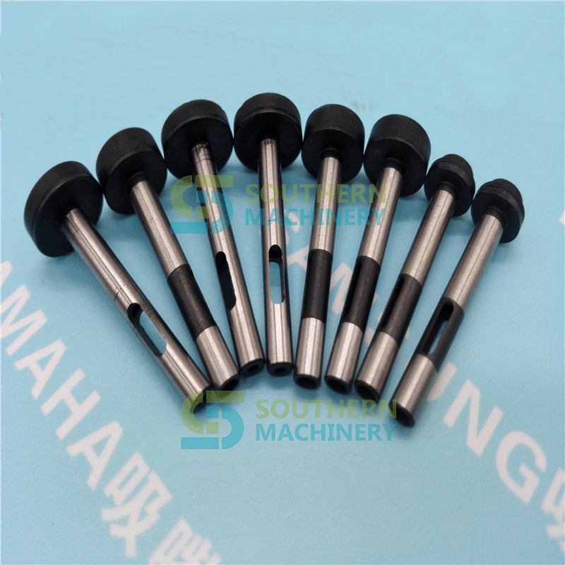
Figure 3 nozzle design. Variations in the design of the nozzle are an important factor in allowing the 0201 component to be received. In order to draw a 0.6×0.3 mm component, the nozzle must have an outer diameter of no more than 0.40 mm. This forms a long, thin nozzle shaft that is fragile but must also maintain precision to maintain high reliability of suction. Changes from the linear axis to the tapered design increase the nozzle strength and allow the nozzle to resist bending (Figure 3).
Matrix structure. All machines generate vibrations during operation. The base frame design is a key first step in reducing the speed and motion effects of vibration and harmonic resonance. By using a cast iron base frame and state-of-the-art structural technology, vibration and harmonic resonance can be reduced to a controllable level within the machine, so that negative effects can be dealt with.
Up to standard
Through all six key factors, the obstacles to reliable 0201 placement have been eliminated. As a result, R&D’s focus has shifted to newer, smaller components, and 0201 is no longer considered a leading edge component packaging technology.
For 0201 component placement, the accepted process window is approximately 75 μm X and 75 μm Y at 3 。. To achieve 6 贴 placement reliability, the X and Y tolerances must be reduced to 50 μm. The latest high-speed placement equipment has a rating of 66μm with an actual standard deviation of approximately 35~45μm. As the 0201 component becomes more widely used and the manufacturing process becomes tighter, improved accuracy can be achieved.
The difference in component size between suppliers poses a challenge to 0201 feeding and placement. Bulk feeding is being opened and should be available in 2001.
Although the machine now has this capability, only a small percentage of users will be ready to take the 0201 placement in the next 12 to 24 months. This is similar to the introduction of a ball grid array (BGA) and 0402 components, in which the machine’s capabilities are ahead of the process state.

Challenge ahead
While the placement of 0201 components is now a standard feature of new placement equipment, additional work is needed to improve the overall process for the end user. The relationship between machine builders, component suppliers, board manufacturers, formwork factories, and solder paste manufacturers needs to be strengthened to create a more seamless development process. The end result will be a unified understanding of the process and a better working relationship that will benefit end users, especially by making new production technologies faster and more efficient.

By Ming Gan, ming@smthelp.net

Printed Circuit Boards Assembly (PCBA) Process

Electronics are an integral part of our daily lives. Everything from our smart phones to our cars includes electronic components. At the heart of these electronics is the printed circuit board, also known as a PCB.

Most people recognize printed circuit boards when they see them. These are the small green chips covered in lines and copper parts you’ll find at the heart of gutted electronic devices. Made with fiberglass, copper lines and other metal parts, these boards are held together with epoxy and insulated with a solder mask. This solder mask is where that characteristic green color comes from.

However, have you ever observed those boards with components solidly stuck on? Never regard them as just decorations of a PCB board. An advanced circuit board won’t be able to give its functionality until components are mounted on it. A PCB with components mounted on is called an assembled PCB and the manufacturing process is called PCB assembly or PCBA for short. The copper lines on bare board, called traces, electrically link connectors and components to each other. They run signals between these features, allowing the circuit board to function in a specifically designed way. These functions range from the simple to the complex, and yet the size of PCBs can be smaller than a thumbnail.

So how exactly are these devices made? The PCB assembly process is a simple one, consisting of several automated and manual steps. With each step of the process, a board manufacturer has both manual and automated options from which to choose. To help you better understand the PCBA process from start to finish, we’ve explained each step in detail below.

Step 1: Solder Paste Stencili

The first step of PCB assembly is applying a solder paste to the board. This process is like screen-printing a shirt, except instead of a mask, a thin, stainless-steel stencil is placed over the PCB. This allows assemblers to apply solder paste only to certain parts of the would-be PCB. These parts are where components will sit in the finished PCB.Solder Paste Composition | PCBCart

The solder paste itself is a greyish substance consisting of tiny balls of metal, also known as solder. The composition of these tiny metal balls is 96.5% tin, 3% silver and 0.5% copper. The solder paste mixes solder with a flux, which is a chemical designed help the solder melt and bond to a surface. Solder paste appears as a grey paste and must be applied to the board at exactly the right places and in precisely the right amounts.

In a professional PCBA line, a mechanical fixture holds the PCB and solder stencil in place. An applicator then places solder paste on the intended areas in precise amounts. The machine then spreads the paste across the stencil, applying it evenly to every open area. After removing the stencil, the solder paste remains in the intended locations.

Step 2: Pick and Place

After applying the solder paste to the PCB board, the PCBA process moves on to the pick and place machine, a robotic device places surface mount components, or SMDs, on a prepared PCB. SMDs account for most non-connector components on PCBs today. These SMDs are then soldered on to the surface of the board in the next step of PCBA process.

Traditionally, this was a manual process done with a pair of tweezers, in which assemblers had to pick and place components by hand. These days, thankfully, this step is an automated process among PCB manufacturers. This shift occurred largely because machines tend to be more accurate and more consistent than humans. While humans can work quickly, fatigue and eyestrain tends to set in after a few hours working with such small components. Machines work around the clock without such fatigue.Surface Mount Technology | PCBCart

The device starts the pick and place process by picking up a PCB board with a vacuum grip and moving it to the pick and place station. The robot then orients the PCB at the station and begins applying the SMTs to the PCB surface. These components are placed on top of the soldering paste in preprogrammed locations.

 Step 3: Reflow Soldering

Once the solder paste and surface mount components are all in place, they need to remain there. This means the solder paste needs to solidify, adhering components to the board. PCB assembly accomplishes this through a process called “reflow”.

After the pick and place process concludes, the PCB board is transferred to a conveyor belt. This conveyor belt moves through a large reflow oven, which is somewhat like a commercial pizza oven. This oven consists of a series of heaters which gradually heat the board to temperatures around 250 degrees Celsius, or 480 degrees Fahrenheit. This is hot enough to melt the solder in the solder paste.

Once the solder melts, the PCB continues to move through the oven. It passes through a series of cooler heaters, which allows the melted solder to cool and solidify in a controlled manner. This creates a permanent solder joint to connect the SMDs to the PCB.

Many PCBAs require special consideration during reflow, especially for two-sided PCB Assembly. Two-sided PCB assembly need stenciling and reflowing each side separately. First, the side with fewer and smaller parts is stenciled, placed and reflowed, followed by the other side.

tep 4: Inspection and Quality Control

Once the surface mount components are soldered in place after the reflow process, which doesn’t stand for completion of PCBA and the assembled board needs to be tested for functionality. Often, movement during the reflow process will result in poor connection quality or a complete lack of a connection. Shorts are also a common side effect of this movement, as misplaced components can sometimes connect portions of the circuit that should not connect.

Checking for these errors and misalignments can involve one of several different inspection methods. The most common inspection methods include:
• Manual Checks: Despite upcoming development trend of automated and smart manufacturing, manual checks are still relied on in PCB assembly process. For smaller batches, an in-person visual inspection by a designer is an effective method to ensure the quality of a PCB after the reflow process. However, this method becomes increasingly impractical and inaccurate as the number of inspected boards increases. Looking at such small components for more than an hour can lead to optical fatigue, resulting in less accurate inspections.
• Automatic Optical Inspection: Automatic optical inspection is a more appropriate inspection method for larger batches of PCBAs. An automatic optical inspection machine, also known as an AOI machine, uses a series of high-powered cameras to “see” PCBs. These cameras are arranged at different angles to view solder connections. Different quality solder connections reflect light in different ways, allowing the AOI to recognize a lower-quality solder. The AOI does this at a very high speed, allowing it to process a high quantity of PCBs in a relatively short time.
• X-ray Inspection: Yet another method of inspection involves x-rays. This is a less common inspection method — it’s used most often for more complex or layered PCBs. The X-ray allows a viewer to see through layers and visualize lower layers to identify any potentially hidden problems.

The fate of a malfunctioning board depends on PCBA company’s standards, they will be sent back to be cleared and reworked, or scrapped.

Whether an inspection finds one of these mistakes or not, the next step of the process is to test the part to make sure it does what it’s supposed to do. This involves testing the PCB connections for quality. Boards requiring programming or calibration require even more steps to test proper functionality.

Such inspections can occur regularly after the reflow process to identify any potential problems. These regular checks can ensure that errors are found and fixed as soon as possible, which helps both the manufacturer and the designer save time, labor and materials.

     Thru-Hole Technology (THT) Assembly Process

As a traditional PCB assembly method, thru-hole mounting process is accomplished through collaboration of manual procedure and automatic procedure.
• Step 1: Components Placement – This step is achieved manually by professional engineering staff. Engineers need to quickly, yet precisely place components on corresponding positions based on client’s PCB design files. Component placement must conform to regulations and operation standards of thru-hole mounting process to guarantee high quality end products. For example, they have to clarify polarity and orientation of components, to stop operating component from affecting ambient components, to make completed component placement compatible with corresponding standards and to wear anti-static wristbands when dealing with static-sensitive components like ICs.
• Step 2: Inspection & Rectification – Once component placement is completed, the board is then placed in a matching transport frame where board with components plugged in will be automatically inspected so as to determine whether components are accurately placed. If issues concerning component placement are observed, it’s easy to get them rectified immediately as well. After all, this takes place prior to soldering in PCBA process.
• Step 3: Wave Soldering – Now the THT components should be accurately soldered onto circuit board. In the wave soldering system, the board moves slowly over a wave of liquid solder at high temperature, approximately 500°F. Afterwards, all leads or wires connections can be successfully obtained so that thru-hole components are firmly attached to the board.

Surface Mount Technology (SMT) Assembly Process

Compared with thru-hole mounting process, surface mounting process stands out in terms of manufacturing efficiency because it features a totally automatic mounting PCB assembly process from solder paste printing, pick and place and reflow soldering.
• Step 1: Solder Paste Printing – Solder paste is applied on the board through a solder paste printer. A template ensures that solder paste can be accurately left on correct places where components will be mounted, which is also called stencil or solder screen. Because quality of solder paste printing is directly associated with quality of soldering, PCBA manufacturers focusing on high quality products usually carry out inspections after solder paste printing through a solder paste inspector. This inspection guarantees printing has achieved regulations and standards. If defects are found on solder paste printing, printing has to be reworked or solder paste will be washed off prior to second printing.
• Step 2: Components Mounting – After coming out of solder paste printer, PCB will be auto-sent to pick-and-place machine where components or ICs will be mounted on corresponding pads in the effect of tension of solder paste. Components are mounted on PCB board through component reels in the machine. Similar to film reels, component reels carrying components rotate to provide parts to the machine, which will quickly stick parts to the board.
• Step 3: Reflow Soldering – After every component is placed, the board passes through a 23-foot-long furnace. A temperature of 500°F causes the solder paste to liquefy. Now the SMD components are bound firmly to the board.

THT – Through Hole Technology (AI)
PCB Electronic manufacturing
THT PCB Assembly auto insertion machine.
AI, Auto Insertion : Axial Inserter; Radial Inserter; JW (Jumper Wire) Inserter; Odd form Inserter; PIN inserter; Eyelet Inserter; Terminal Inserter
IM, Insertion Mount,
MI,Manual Insertion,
DIP Wave soldering

SMT-Surface Mount Technology(SMT)
BHS: PCB board handling system, Loader, Unloader, Conveyor,Shuttle
Printer: Solder paste screen printer
SPI: Solder Paste Inspection
Mounter: Chip Mounter, Pick and Place, IC Mounter, High Speed Mounter
AOI Reflow Oven

Shenzhen Southern Machinery Sales and Service Co.,Ltd
Add :Rm 1806,Block 3, Jinyun COFCO, Qianjin 2 Road,Xixiang,Baoan District, Shenzhen City, China
TEL: 0755-83203237; FAX:0755-23240492 website:www.smthelp.net whatsapp:+86 137 6048 1664    shaoyong@smthelp.net

Bulk material handle method and process on SMT production line

Bulk material handle method and process on SMT production line

SMT patch bulk material problems have plagued many SMT people, as we all know, once the placement machine starts, there will definitely be a problem in the SMT production line. For a variety of reasons, many bulk materials are produced, thrown, or are originally bulk materials, or other reasons. Some bulk materials, such as resistors, capacitors, inductors, etc., are not easily distinguishable and have little value in themselves, and there is no value for reuse. However, for large devices, especially some imported chip components, they are of high value and can be distinguished and distinguished, so they are generally reused. However, for scattered components, if the original package is a tray or a suitable tray, the problem may be solved better. Otherwise, it may be more difficult to handle. Southern Machinery today will talk about the handling of bulk material in the SMT production line. Method and process.
First, the bulk material handle process

Collecting materials – material personnel sorting materials – using electrostatic bags to pack – paste material specifications – technicians based on bulk material springboard – hand paste bulk material – QC confirmation

Second, the definition

Bulk material: refers to the components that are separated from the original packaging during the production process due to machine throwing, or loading and unloading materials.

Third, job responsibilities

Material staff: responsible for the collection, classification, identification, storage, placement, and placement information of bulk materials, and the material loss rate is calculated according to the order.

QC in front of the furnace: responsible for the manual placement of bulk materials, the front back grain and material code confirmation, PCBA mark, and the classification of bulk materials.

Technician: Responsible for programming, patch production, monitoring patch quality distribution and timely improvement.

QC after the furnace: It is responsible for checking and checking the first piece of all the machines, and the quality is abnormal. Immediate feedback is provided to the front station to improve and track.

Fourth, the work content

  1. In the production process, the material may be thrown due to equipment and other factors, so the operator should check the material step before the patch and after the shift, and check the throwing box and the trash can each time the garbage is dumped. Collect the bulk material and report to the supervisor about excessive bulk material anomalies.
  2. According to the shape of the components, the bulk material is classified according to the shape of the components, and the back code of the components is checked to determine the material code. Then, the checked bulk materials are packed in anti-static bulk box or bulk bag, and the material code identification is performed to confirm the signature of the person. .
  3. When using machine mounting, the operator should first check whether the components are consistent with the normal materials, confirm the material number, and then load the FEEDER tape.
  4. The first piece of material feeding / mid-way refueling, the technician firstly inspects the materials that will be short of materials in the machine half-hour in advance, and collects the materials of the same item number in the component preparation area, and check them correctly, and submit them to the quality department QC/materials. The staff will check again and confirm the total signature of the refueling sheet.
  5.  

Methods and measures to improve the production efficiency of SMT production line

Abstract

Nowadays, the market competition is more and more intense, how PCB assembly plant in such an environment can to be invincible. The first point is to reduce its production costs. To achieve this goal, the most important way is to improve the production efficiency of the production line. This paper discusses some measures and measures to improve the efficiency of SMT production line based on the author’s work practice.

S-K 100 LED SMT line


一. Processing of chip mounting program

SMT production line consists of a number of equipment, including screen printing machine, chip mounter, reflow soldering and so on, but in fact the speed of the production line is determined by the chip mounter. A SMT production line usually consists of a high-speed machine and a high-precision chip mounter, the former mainly mounting chip components, while the latter mainly mounts IC and Odd-form components. The entire SMT production line has the maximum production capacity when the two patch machine completes an affixed time (hereinafter referred to as the mounting time) and the hourly hour. In order to achieve this goal, we can process the mounting procedure according to the following methods.

  1. Load distribution balance. Reasonable distribution of the number of mounting components of each device, so as to make the installation time of each device equal. When we first assign the number of mounting components for each equipment, there is a large gap in the mounting time. This requires the adjustment of the production load of all the equipment on the production line according to the mounting time of each equipment, and the part of the equipment on the equipment is moved one part to the other. The balance of current load distribution.
  2. Equipment optimization. Each patch machine has a maximum value of the patch speed, for example, the YV100 of YAMAHA is called 0.25 seconds / slice, but in fact the speed value is realized under certain conditions. To optimize the numerical control program for each equipment, it is to make the chip mounter meet these conditions as much as possible in the production process, so as to achieve the highest speed mounting and reduce the installation time of the equipment. The principle of optimization depends on the structure of the equipment. The placement machine for X/Y structure is usually optimized according to the following principles.

  • As far as possible, the mounting head can be picked up at the same time.
  • When arranging the mounting program, the same type of components are arranged together to reduce the number of changing suction nozzles when the mounting head picks up the components and save mounting time.
  • More supplies should be placed near the material station near the PCB.
  • During the process of picking up and releasing, try to collect materials only from the front or rear material stations, so as to reduce the moving distance of the head.
  • In every cycle of collection and circulation, the head should be loaded.

Notice: Some principles will conflict when optimizing the program, which requires compromise consideration to select the best optimization plan. Optimization software can be used in load distribution and equipment optimization. The optimization software includes equipment optimization program and production line balance software. The optimization procedure of the equipment is mainly to optimize the placement procedure and the configuration of the feeder. After the components BOM and CAD data are obtained, the mount program and the feeder configuration table can be generated. The optimization program will optimize the movement path of the mounting head and the configuration of the feeder, and reduce the moving distance of the mounting head as much as possible, thus saving the time of the mounting. The production line balancing software is an effective tool for the optimization of the whole production line. The optimization software adopts a certain optimization algorithm. The current optimization software has been intellectualized, and the optimization process can be completed faster and better.

Customer scene IN Brazil 2

二.Eliminating of bottlenecks

The SMT production line is made up of a number of automatic equipment. When a certain equipment is slower than other equipment, the device will be the bottleneck for the speed improvement of the whole SMT production line. According to a sample of 19 factories (Table 1), bottlenecks are often found in chip mounters, and only by adding chip mounters can they be eliminated. Of course, this requires a large amount of capital investment, but it can make full use of the production capacity of other equipment, far more than the investment of a SMT production line. What type of patch machine is added depends on the bottleneck of the production line. In general, it is best to buy a high speed, multi-functional chip mounter machine, because it has the features of both high speed and high precision machines. The range of mounting components covers the high precision machine and the high speed machine. It can solve the problem caused by the high speed machine or the high precision machine. Bottleneck problem. At present, the development trend of chip mounter is also developing in this direction to meet the needs of the market.

Bottleneck of process steps Percentage
High precision chip mounter 32
High Speed Chip Mounter 21
Online testing (ICT) 16
functional testing 16
Other 15
Total 100

Table 1 –Distribution of the most common bottlenecks in a factory

Adding a patch machine to the production line can solve the bottleneck problem and speed up the pace rate. This method provides more production capacity and more feeder position to better balance the production line without significantly increasing the complexity of production line management, which is much more than a single increase in the production capacity of a chip mounter machine. It’s much more powerful.

Sample of SMT Line Configuration

三.Implementing strict and effective management measures

1.SMT equipment is a precision equipment of mechatronics. Strict and effective management measures are an important way to improve the efficiency of SMT production line. If the components to be supplemented in advance are installed on the standby feeder, the production line will assemble the last few pieces of the batch number in front of the front, and do well the preparation of the next batch of products on the production line and so on.

2.The SMT production line is a large production line, and the output value is calculated in seconds. And the fluency of production and quality of products, besides equipment and environmental factors, human factors play a very important role. For example, if the operator is familiar with the equipment, it will take less time to eliminate problems in the production process, and it will also save production time and improve production efficiency. Therefore, we must attach great importance to the training of employees. In addition to regular professional training, some professional SMT books and periodicals should be used as teaching materials to organize the staff to learn, to cultivate the love of SMT and to improve the comprehensive business level of each person.

3.Regular inspection and maintenance of SMT equipment is also a powerful guarantee to ensure its full effect. Many companies often neglect this because of their heavy production tasks. Once the equipment fails to produce normally, the loss caused by the shutdown is far greater than the cost of regular shutdown inspection and maintenance of the equipment. Therefore, we must emphasize the regular inspection and maintenance of the equipment, so that the equipment is in good condition.

Vacuum loader &Buffer unloader (1.5 M)

Summary

SMT production needs high investment, but if the management and use is appropriate, and pay attention to several aspects mentioned above by editor , It will fully tap the production potential of the SMT production line, improve production efficiency, in a few years will take back all of the investment, to achieve “high input, high output”.

Smart factory--Loader & unloader from Southern Machinery

Use of PCB Pallets in Wave Soldering

Use of PCB Pallets in  Wave Soldering
Patch components are used more and more on the circuit board, but there are still some perforated components between them. For this kind of board, selective soldering is the best solution, but not every company has enough funds to purchase selective soldering equipment, or the number of this type of circuit board is too small, specifically to buy selective soldering equipment is not Cost-effective. Manual welding is prohibited in certain industries such as the automotive industry

Wave soldering pallet 8

Therefore, in PCB wave soldering, using trays to block those patch components is a good method: reliable, fast production, and adaptability to high-capacity requirements.

www.smthelp.com

Wave soldering pallet 2

The benefits of using trays:
Lead-free soldering requires higher soldering temperatures. Therefore, the circuit board is more easily bent during welding. The tray provides maximum protection of the circuit board during soldering and prevents bending.

Similarly, in the automotive and consumer electronics industries, many special-shaped circuit boards have emerged for the needs of applications. It is sometimes difficult to transport these shaped plates with conventional chain rails and mesh belts, and placing the circuit board plates in trays allows any type of circuit board to be shipped.

Wave soldering pallet 1

By soldering some of the bottom components through the tray, it is also possible to use PCB wave soldering equipment for selective soldering of the product.

Since most trays are thick (sometimes 15 mm), solder certainly does not flow to the top of the board. The oxide layer on the solder surface will also be washed away by the edge of the tray before the board reaches the peak, so that when the solder starts, the tin is relatively clean.Wave soldering pallet 6

By adding some stiffening strips to the tray, it can increase its hardness to withstand high-strength welding. It is also possible to install heat-absorbing blocks, component fixing devices and some other auxiliary devices on the upper part.

The use of pallets also helps standardize the width of the product line, soldering different circuit boards on the same production line, and can use bar code readers and other identification tools to quickly change process programs for different boards.

Although there are many advantages to using trays in lead-free soldering, it can also cause solder balls.

Requirements for pallet materials:
In order to maximize the service life of the trays, the trays must be made of materials that can withstand high temperatures and harsh process conditions, especially for lead-free soldering.

www.smthelp.com

Wave soldering  tray 1

To meet these requirements, the material used to make the tray must meet the following characteristics:
• High dimensional stability
• Good thermal shock resistance
• Can remain flat after repeated use
• Corrosion resistance (flux and cleaning agent)
• Does not absorb moisture

The use of the tray brings the process problems:
The flux system must be able to spray the circuit board completely with flux. Poor tray designs can lead to “shadow effects” in flux spraying: Some parts of the board have insufficient flux or no flux at all. The flux must be sprayed onto the board and spread through the capillary action.

Before the tray touches the crest, it must be heated in the preheating unit. A typical preheating configuration is a combination of heat pipes and hot air forced convection. If the temperature drops before contact with the peak, the tray will have an endothermic effect, making the welding process difficult to control.

The use of trays requires a wave height of up to 0.5 inches (12.5 mm). In the case of such a high pump speed, the use of nitrogen can help reduce dross. When using pallets in lead-free soldering, Vitronics Soltec’s perturbed “smart wave” can also promote tinning of the perforated component.

In addition, we must pay special attention to keeping the circuit board in the pallet flat. If there is a gap between the circuit board and the tray, the flux will flow into the gap, and the solder will flow to the board when passing through the peak. This will cause solder residue on the board.

Wave soldering  tray 3

The gap between the circuit board and the tray may cause solder residue on the circuit board

Circuit board and tray design recommendations:
Avoid placing larger components near the piercing element as this can cause shadowing effects and tin difficulties.

Leave proper clearance around the pins and edges of the through-hole components so that solder can flow. These tin guides will guide the solder to the seat of the tray opening, while also greatly improving the solder flowability.

www.smthelp.com

Wave soldering  tray 4

The tin slot at the tail of the tray allows the solder to flow smoothly back to the tin tank

The opening of the tray should be as large as possible to facilitate the flow of solder. This will reduce some of the welding defects, such as: short circuit and solder balls. At the same time, it is also beneficial to the solder filling of the through hole, because the large opening also means that there is more energy to enter the welding area.

Prepared by :ming@smthelp.com

How to prevent static electricity in the process of SMT placement machine?

How to prevent static electricity in the process of SMT placement machine?

Southern Machinery Anti Static Tools & Supplies

In the SMT production line, we will encounter the problem of static electricity, from the friction between the clothes and the dry air to the dry air, which is the end of the duckweed. If the condition is suitable, it is a few volts and the peak is hundreds of kilovolts, so anti static is the need to do in our work, today, the south. Give some measures to introduce mechanical anti electrostatic patch SMT.

static clothing, antistatic shoes (conductive shoes)
static clothing, antistatic shoes (conductive hats)

Http://www.smthelp.com

Static electricity has three: static clothing, antistatic shoes (conductive shoes), electrostatic hand rings, antistatic shoes and electrostatic hand rings to guide the human body to avoid accumulation in the human body.
Ordinary clothes will have great electrostatic voltage in the walk (>1000V). And antistatic clothing does not happen when it moves. This is the main role of antistatic clothing, long strip antistatic clothing can not shield the inside of the clothing produced static (after wearing still >1000V), grid – like antistatic clothing can be shielded (<200V), the static electricity generated through the floor and the grounding line of various parts of the plant to the outside of the general grounding wire.

Http://www.smthelp.com

一,The purpose of preventing static electricity

1, strengthen the consciousness of the workers on the anti static operation

2, reduce the poor production caused by static electricity

3, prevent static electricity from causing damage to the product

二,Scope of application: all SMT production lines

三,The reasons

The generation of static electricity is not perceived, but the static electricity produces the voltage of tens of thousands of volts. When the static electricity comes into the tip (the static release point, such as the human finger), it releases all the energy in a moment, causing the contact material to be struck by electric shock, causing the capacitance, IC, line road and so on to be destroyed and burned, so that the product is strict. In the case of heavy damage, static electricity measures should be taken. .

四,The contents of the operation

Anti Static Tools & Supplies SMT magazine rack&turnover rack
Anti Static Tools & Supplies
SMT magazine rack&turnover rack

(一)Prevention and treatment of human static electricity

1, the workers should wear electrostatic clothing, work shoes;

2, the operator should take electrostatic gloves when working.

3, the operator should take an electrostatic ring in the operation.

(二)Prevention and control of static electricity

  1. Make use of electrostatic materials to produce production tools.

2, the storage place to prevent static electricity;

(三)Prevention and control of static electricity of a worktable / mobile vehicle

1, the anti static film should be pasted on the work table.

2, the operation platform / mobile vehicle must have antistatic grounding chain.Prevention of equipment static electricity: good grounding wire

(四)Prevention and control of material static electricity

  1. When the material is taken, the operator should use the antistatic method: with electrostatic gloves and electrostatic rings.

2, the material storage should be anti static measures: material cabinet to paste electrostatic film, grounding chain.

3, there should be anti-static measures in temporary storage area: installing grounding chain.

(五)Prevention and control of static electricity related to production: anti static measures should be taken when using items related to production: static wires and antistatic films.


五, Note:

  1. The online operators should strictly abide by this rule
  2. The online operators are supervised by the team leader, and the engineers are supervised by the engineers.


SC-2500S PCB Router Separator

SC-2500S PCB Router Separator

SC-2500S PCB Router Separator


Features:

1, using the next vacuum mode, in line with the theory of free fall, good dust collection effect.

2, special jig fixed more solid, to avoid the poor positioning caused by the cutting accuracy error.

3, the system automatically fixes according to the product installation location, to ensure high-precision product cutting requirements.

4, the static eliminator is installed in addition to electricity, dust blower continued to work to eliminate static electricity generated when cutting high-speed spindle to avoid damage caused by static electricity parts to avoid accumulation of dust due to static electricity.

5, the use of safety doors, reduce noise and dust, improve safety.

Vacuum cleaner with vacuum collection box (according to production capacity or cutting dust collection time scheduled maintenance)


PCB Separator also called PWB Depaneling machine. Rotate router bit to cut high-density component PCB panel to single products v-groove or perforated line. Utilize all of our accumulated technology to help minimize dust attach on PCB. Router machine has following features.


SC-2500S PCB Router Separator specifications:

Function Items

功能项

参数/Hardware Demand

Model

型号

ASC-2500S
Dimension

机台结构

L650*W650*H1765mm
Power

电源

220V/50HZ
Machine Wattage

机台功率

3.6KW
Weight

重量

About 300KG
Cleaner Dimension

吸尘器尺寸

内置式(Inside)/L500*W490*H590mm
Cleaner Wattage

吸尘器功率

2.2KW/220V
Table Dimension

工作台尺寸

260mm*260mm
Cutting Speed

X、Y轴切割速度

0-100mm/s
X,Y,Z axis Driving Speed X、Y、Z轴驱动速度 X、Y轴0-1000mm/s(min),Z轴0-750mm/s(min),伺服马达方式驱动X, Y axis 0-1000mm/s (min), Z axis 0-750mm/s (min), servo motor drive
Repeatability Accuracy 机台重复精度 ±0.01mm
Working Area 工作区域(可加工行程) X:0-260mm,Y:0-260mm,Z:0-80mm
PCB Thickness 切割PCB厚度范围 0.5-5mm
Router Bit Diameter 铣刀直径 0.8-3.0mm
Cutting Precision 切割精度 ±0.01mm
Cutting Ability 切割能力 具有切割直线、圆弧、圆、L型和U型的能力

Linear, Circular, U-curve, Arc, L-curveCutter Change刀具更换系统可手动换刀系统,需工具(随机配送)

Manual, tools needed Cutter Attrition System刀具磨损系统可智能设定铣刀下刀段数(0-5段)

The number of milling cutters (0-5 section)Break Detection断刀检测无(none)Cutter Life Control刀具寿命控制程序控制(controlled by Program)Table NumberTable数量1个Spindle Speed主轴转速60000rpmSpindle Cooling System主轴冷却系统气冷方式Air cooling modeCleaner Mode集尘方式下集尘(collect dust downside)Working Power工作电源220V ,50HZAir press空压供给0.4MpaSafety Device安全装置采用安全防护门加门锁感应器Safety door and door lock sensorMode机型模式离线机型,手工装载卸载PCBA(offline, load and unload PCBA by hand)Auto failure test and repair mode故障自动检知维修模式系统具有自我诊断功能,实时错误信息显示,能直观地查询设备各个IO端口状态,易于排除故障。

Self-diagnosisdisplay failure information in real time, query IO state visually, easy for troubleshootingComputer & Operation system电脑和操作系统工控机、Windows 7

IPC, Windows 7Program Backup程式备份USBSoftware access control软件权限管理密码保护,依权限进入对应操作界面,保护系统重要参数。(Password protectionthe operator enter corresponding interface according to authority to protect important parameters.)Programming编程可视化界面,单个程序切割点容量无限制,切割路径动态模拟。(Visual interface, the cutting point capacity for a single program should be over 400, dynamic simulation of cutting schedule.)Auto correction of the mark pointMark点自动校准功能具备Mark点自动校准功能(Yes)Fixture 治具万用治具可供选择(universal fixture)Voice control噪音控制运行时,噪声小于60分贝(离设备一米距离测量)

≦78 dBmeasured in 1M’s distance Maintenance Period保修周期整机1年或以上,主轴2年或主轴3000小时保养服务。

1 years or more, spindle for 2 years or spindle maintenance service for 3000 hours.Technology Support技术支持及培训提供设备操作、编程,硬件保养,维修培训服务;程序永久免费升级。(Offer service of operation, programming, hardware caring and maintenance training; free upgrade of application. )


主轴Main axis S4225-B60 S4225-B60
CCD IMAGING
丝杆Ball Screw Hiwin进口精密研磨滚珠丝杠Hiwin precise grinding ball screw imported
导轨Lead Rail Hiwin进口直线加宽导轨Hiwin straight widened lead rail imported
伺服电机Servo Motor 松下Panasonic
静电消除器Static Eliminator ADK-801ADK-801
工控主机IPC Host 研华ADHNTECH
运动控制卡Motion control card 固高ADTECH
显示器Monitor 华硕ASUSASUS
控制系统Control System Windows7
操作界面Operation Inteface Windows7
编程Program 在线方式Online
视觉系统Visual System ASC视觉分板机系统像素计算型高精度CCD视觉定位校正系统CCD Visual alignment system
设备尺寸Machine size L1380*W1250*H1875mmL1380*W1250*H1875mm
重量Weight 约300KG
底脚可调高度Foot Height adjustable 50~70mm
板最大厚度Max.PCB Thickness 5mm
整机功率(含集尘器)Power (included dust collector) 4000w
最大转速Max Rotation Speed 60000rpm/min
冷却方式Cool Down 气冷+夹具散热cold air and clamp radiating
更换工具方式Tool replacement 专用扳手更换by specialized tool
最大切割Shear speed 0~100mm/s
最大移动速度Max Moving Speed 1000mm/s
切割重复精度Shear Repeat Accuracy ±0.02mm
集尘器功率Dust Collector Power 2.2kw 220v三相电机2.2kw 220v three phase motor
气压Pressure 0.4Mpa以上0.4Mpa above
编程方式Program mode 在线编程Online program
编辑功能Edit 直线、孔状、圆弧、圆Straight line, hole, arc, circuit
程序存储Procedure Storage 根据需要选择存储位置choose storage position according to needs
配置编程Camera IMAGING高像素彩色CCD IMAGING high pixel color CCD
刀具直径补偿Compensation on Blade DIA 多种补偿方式供用户选择many choices for option
三色灯Three Color Indicator LED三角灯监视机器的各种工作状态LED LED indicator monitoring working status of the machine
刀具好坏检测Blade Inspection 刀具寿命根据用户设定的下沉段数、产品数量及切割长度等方式选择According to PCB quantity and shear length
马达过热检测Motor overheat Inspection 有过载、过热、低电压等保护功能Protection on overload, overheat, low voltage,etc
伺服过载检测Servo overload Inspection 有过载、低电压、线路是否正常等保护功能Protection on overload, low voltage, circuit, etc
主轴寿命跟踪Main axis life Tracking 主轴寿命自动检测Automatic Inspection on Life of main axis
分板计数Shear Qty Counting 分板计数、计时Counter on shear quantity and Time recording
机器报错记录Error Record 软件自动记忆机器所有报警记录automatic memory on all error
轴位置精度Axis Position Accuracy 0.001mm
分板精度Accuracy of Shear ±0.01mm
工作范围保护罩Safety Shell of working range 采用四面门保护方式Using four door and window protection
门的互锁保护传感器Protection Inductor on Interlocking 安全门微动开关感应able to induct inches switch of safety door
紧急停止按钮Emergency Stop Button Yes
铣刀方式Milling 采用左旋铣刀,直径0.8-3.0MM范围可选Milling by left rotation, DIA of 0.8-3.0mm optional
加工方式Process 模拟运行和实际加工,Table可以交替加工不同PCBASimulation and actual operation, a single Table can be alternately processed different PCBA board


SC-3500S Automatic Inline PCB Separator

SC-3500S Automatic Inline PCB Separator

Features:

1, vacuum cleaner built-in vacuum mode, in line with the theory of free fall, dust collection effect is good.

2, the equipment adopts automatic loading and unloading products, can be directly on the wiring body or on the board machine.

3, using a special fixture with products (pcb), to avoid poor placement caused by cutting error.

4, the system automatically fixes the installation error, to ensure product precision cutting requirements.

5.It is equipped with static eliminator. When dividing, the dust remover will work continuously to eliminate the static electricity generated when the high-speed spindle cut. It can avoid the damage caused by the static electricity and avoid the accumulation of dust due to static electricity.

6, the use of safety doors, reduce noise and dust, improve safety.

7, there are follow-up vacuuming function, dust collector attached to the dust collection box (according to capacity cutting needs or dust collection time scheduled maintenance).

8, touch the display as a display, setting, control, can display more content, the operation directly through the touch screen operation, easy to operate.

9, can be directly docking the next equipment, sub-plate processing.

10, in the cutting process, if broken knife, equipment with automatic tool change function, without manual to change the knife.

11, Equipment using Mes system, the factory can control the machine everywhere, equipped with WIFI function can be controlled.


Specifications:


Function Items

功能项

Hardware Demand

Model

型号

ASC-3500S(加皮带)
Dimension

机台结构

(含皮带)L1750*W1100*H1850mm

(不含皮带)L1450W1100H1850mmPower

电源

220V/50HZMachine Wattage

机台功率

5.5KWWeight

重量

About1000KGCleaner Dimension

吸尘器尺寸

内置式(Inside)/L450W450H450mmCleaner Wattage

吸尘器功率

2.2KWTable Dimension

工作台尺寸

350mm*350mmCutting Speed

X、Y轴切割速度

0-100mm/sX,Y,Z axis Driving SpeedX、Y、Z轴驱动速度X、Y轴至少1000mm/s(min),Z轴至少750mm/s(min),伺服马达方式驱动(driven by servo motor)Repeatability Accuracy机台重复精度±0.02mmMechanical hand X, Z stroke机械手X、Z行程X:420mm、I:60mmManipulator X, Z running speed机械手X、Z运行速度200mm/sMechanical hand grasp mode机械手抓取方式真空吸附Precision of repeated positioning of manipulator机械手重复定位精度±0.04mmMechanical hand grab products (PCB) dimensions机械手抓取产品(PCB)尺寸350mm*350mmPCB feeding trackPCB上料轨道皮带输送;宽度60~360mm可调Split plate product分板产品下料皮带输送;宽度420mmWorking Area工作区域(可加工行程)X:300mm,Y:350mm,Z:0-50mmPCB Thickness切割PCB厚度范围0.5-2mm(or thicker),或范围更大 Router Bit Diameter铣刀直径0.8-2.0mmCutting Precision切割精度±0.01mmCutting Ability切割能力具有切割直线、圆弧、圆、L型和U型的能力


Linear, Circular, U-curve, Arc, L-curveCutter Change刀具更换系统自动换刀系统 Automatic tool changing systemCutter Attrition System刀具磨损系统可智能设定铣刀下刀段数(5段)

Smart to set the no. of knife section(0-3)Break Detection断刀检测有(have)Cutter Life Control刀具寿命控制程序控制(controlled by Program)Product testing产品检测有(have)Table NumberTable数量1个Table FunctionTable功能并行Table运行方式;设备能实现1个Table联动功能(1 tables run in parallel)Spindle Speed主轴转速60000rpmSpindle Cooling System主轴冷却系统风冷方式(air cooling)Cleaner Mode集尘方式下集尘(collect dust downside)Working Power工作电源220V ,50HZAir press空压供给0.5Mpa以上(above)Safety Device安全装置采用安全防护门或感应器(security door or sensor)Mode机型模式在线机型,全自动装载卸载PCBA(offline, load and unload PCBA by hand)Auto failure test and repair mode故障自动检知维修模式系统具有自我诊断功能,实时错误信息显示,能直观地查询设备各个IO端口状态,易于排除故障。

Self-diagnosisdisplay failure information in real time, query IO state visually, easy for troubleshootingComputer & Operation system电脑和操作系统工控机、Windows 7或以上版本。

PICWindows 7 or more advanced versionProgram Backup程式备份USBSoftware access control软件权限管理密码保护,依权限进入对应操作界面,保护系统重要参数。(Password protectionthe operator enter corresponding interface according to authority to protect important parameters.)Programming编程可视化界面,单个程序切割点容量无限制,切割路径动态模拟。(Visual interface, the cutting point capacity for a single program should be over 400, dynamic simulation of cutting schedule.)Auto correction of the mark pointMark点自动校准功能具备Mark点自动校准功能(Yes)Fixture 治具ASC-3500S专用治具ASC-3500S special fixtureVoice control噪音控制运行时,噪声小于60分贝(离设备一米距离测量)

≦78 dBmeasured in 1M’s distance Maintenance Period保修周期整机1年或以上,主轴建议2年以上并在保内提供主轴3000小时保养服务。

Over 1 year for the whole machine, and over 2 years for the spindle, and the spindle enjoys 3000 hours’ maintenance during the periodTechnology Support技术支持及培训提供设备操作、编程,硬件保养,维修培训服务;程序永久免费升级。(Offer service of operation, programming, hardware caring and maintenance training; free upgrade of application. )


SC-900 Multi-Cutter PCB Separator For cutting: 0.2mm-5mm thickness of the panelized PCB aluminum, copper, FR4, glass


SC-900 Multi-Cutter PCB Separator

For cutting: 0.2mm-5mm thickness of the panelized PCB aluminum, copper, FR4, glass, etc., special plate

SC-900 Separator machine features:

1, the use of multiple sets of upper and lower knife while cutting

2, the bottom of the device with adjustable foot castors, easy to move equipment, non-moving need to be stable and fixed; feet Cup adjustable height 50MM or more;

3, equipped with SMEMA interface communication with other devices can be linked, with reserved network interface, the follow-up factory aspects of networking;

4, the device uses power: AC230V gas source: 4-6KGF / cm2

5, the necessary safety devices;

6, the equipment needs to operate smoothly, the necessary test components;

7, according to the normal production capacity needs to reach 1500PCS / H or more

8, there are data monitoring statistics output: boot time monitoring, capacity monitoring, equipment failure information and automatic rejection system

9, using multiple groups simultaneously cut down on the knife

10, the distance between the knife can be accurately adjusted, sub-board thickness to be met: 0.6MM-3.5MM up and down the distance between the knife can be accurately adjusted, sub-board thickness to be met: 0.6MM-3.5MM

11, the knife and the knife gap can be adjusted according to the PCB board V-CUT spacing, precision control in the 0.1MM

12, the distance between two adjacent blades can be adjusted between 8MM-25MM, can quickly adjust the required width;

13, circuit board material: aluminum, copper, FR4, glass fiber board;

14, Conveyor line speed can be adjusted;

15, the product pick and place institutions can be adjusted according to the width of the product;

Specifications

ASC-900

Machine Size

L2160*570*1050mm

Maximum Length

Unlimited

Cutting Speed

80, 120, 200, 400mm/s

Cutting thickness

0.2-5mm

Voltage

230V/50Hz110V/60Hz)

Machine Weight

158KG

Power

120W

Cutting number

9 multi-join

Knife quantity

40 pcs

Spacer

40 pcs

Software Configuration

English Version


45798401 Tube Continuity to save Auto Insertion machine running cost


45798407 Tube Continuity

45798406 Tube Continuity

45798405 Tube Continuity

45798404 Tube Continuity

45798403 Tube Continuity

45798402 Tube Continuity

45798401 Tube Continuity


Preventive Maintenance Schedule


WARNING Do not perform any preventive maintenance with power on unless specifically instructed otherwise. Failure to observe this warning may result in personal injury.


CAUTION When performing machine maintenance, wear a wrist strap connected to ground to prevent electrostatic discharge damage to printed circuit boards.


500,000 Cycles Check: Perform Maintenance:

  1. Clean the clinch scrap tube with the pipe cleaner (40940101) twice daily (every 250,000 cycles).


3,000,000 Cycles Check: Perform Maintenance:

  1. Check for excessive wear on the pins 1. Lubricate the cutter linkage pins with Magnalube and linkage. Replace if necessary. (40833809).


12,000,000 Cycles Check: Perform Maintenance:

Check for worn cutters and bushings on 1. Replace if necessary. the cut and clinch by observing the quality of the production board component leads. 2. Lubricate the clinch lead screw with Super Blue (BLKM07680). 3. Replace the O-rings and bumpers in the cutter cylinders on the cut and clinch assembly. 4. Lubricate the three surfaces of the notch in the rocker guide Kendall Super Blue (BLKM07680).

48,000,000 Cycles Check: Perform Maintenance: 1. Lubricate the anvil slides with Kendall Super Blue (40833838) and grease gun (47408201).


JUKI nozzle :Which is the most used?

JUKI nozzle

Use black material Seiko forming – wear long life

German technology to create high precision – beyond the original quality

  1. Applicable models: JUKI placement machine

KE2000 series KE2010 KE2020 KE2030 KE2040 KE2050 KE2060 KE2070 KE2080 KE-3010A KE3010ACL KE3020VA JX series JX-100 JX-200 JX-300LED JX-100LED JX-350 , FX series FX-1, FX-2, FX-3, FX-3R, FX-3RA.

  1. Using nano-aviation materials, through ultra-precision machining and grinding, the nozzle will not wear out and become white. It can be durable.


JUKI nozzle JUKI nozzle JUKI nozzle JUKI nozzle

JUKI nozzle

JUKI nozzle


JUKI nozzle


● our advantages:

Production advantages: the use of close CNC / milling machine, lathe, grinder, line cutting 35 world first-line brand processing equipment, to make Seiko quality. Non-standard nozzles and the workpiece can be quickly customized, 2-3 working days can be delivered, ultra-rush orders can be shipped the same day.

Long-term inventory, a large number of conventional suction nozzle stock, immediately after the order can be shipped, order to reach 1,000 US dollars can be shipped for free
Price advantage: Suction nozzle and SMT placement machines are a variety of peripheral equipment accessories are sold at preferential prices. Truly Seiko quality, the Chinese price, used to repay customers. We only do Seiko quality, low-end high-margin products do not do!
Team advantage: We have a group of 20 years of experience with automatic insertion machine, SMT machine service engineer team
Payment advantages: As long as you are a factory customer, we can do monthly payment

JUKI nozzle

Buy now for just $ 25, please click on the link for more details


We also sell all kinds of brand accessories, such as JUKI,universal, panasonic, yamaha, samsung, Fuji, Siemens, TDK

If you have any needs, please feel free to contact us:

info@smthelp.com

ming@smthelp.com

JUKI nozzle

FUJI XP142/143 2.5/3.7# Nozzle

 SAMSUNG nozzle  CP45FV/SM420 CN065 CN040 CN220 CN400 TN220 TN065

Panasonic nozzle Panasert- smt nozzle for pick and place machine


SMT Nozzle Cleaning Machine Operation Manual


Nozzle Cleaning Machine

Operation Manual


Please read the instructions carefully before user operation

Preface

First of all, we sincerely thank you for choosing the SMT peripheral automation machine produced by our company. This company specialized production: conveyor, automatic feeding detection machine, vacuum suction machine, stacked on the machine, parallel transfer, angle conveyor, turning machine,machine, double buffer for the same reflow furnace system, a series of automated production machine. According to the customer’s requirements, we can develop and design a series of automation machine, in order to meet the customer’s high efficiency, energy saving, downsizing and other production needs. This manual describes the use of methods and machine maintenance and precautions, in front of the machine, please carefully read this manual, and it will be properly preserved, wrong operation may cause the device does not operate normally or damaged parts. Due to man-made machine failure or parts damage, will not apply to the company’s exemption free warranty service range. Without permission of the company, please do not disassemble or replace the machine parts, nor applicable to the company’s free warranty warranty service range. As to the improvement and partial renewal of the product, we will not make further instructions. If you have any doubts, please contact our company for consultation.


Important matters and safety instructions

When using this Cleaning Machine, you must abide by these safety devices.

All attention should be taken to avoid accidents and damage to the instrument.

1. please read and understand the user’s manual carefully before using or operating this machine.

2. non – instrument maintenance personnel and untrained personnel should not use this machine at will.

3. please avoid the use of this machine in the vicinity of the strong electromagnetic interference source.

4. please avoid the use of this machine in the environment with high humidity.

5. maintenance, please turn off the power, to prevent damage to components.

6. instruments are used, they should be kept stable to prevent falling.

二、Appearance introduction


1Liquid storage tank

When the cleaning liquid is completely unused, the liquid can be added, and the addition method is referred to the addition of the solution step.

2Emergency switch

After pressing the emergency switch, PLC is out of power and the equipment stops working

6Storage tank

Store the cleaned liquid and put out of the liquid in time.

Step: the tank is pulled out, carefully put out the liquid.

三、Operation steps

1. connect the power supply (220V, 50HZ) and gas supply (0.6MPa), turn on the power switch.

2.Check whether there is a liquid on the left level (the grooves pipe), if its no,then add liquid (detailed please refer the step of adding the liquid).

3. Switch is normal opening , and the touch screen appears as the Figure 3.1 interface


Figure 3.1

4. Click Figure 3.1 [into system], and appear on the interface, such as Figure 3.2. If you need to set parameters, enter the manual tool interface for parameter settings (detailed please refer the parameter settings).When you set it up, Hit [save parameter].


Figure 3.2

Note: first use the parameters set first ( refer parameter settings) and then do the next step.

5. When nozzle is placed well,closed the door tightly ,and set the parameters(can skip). Confirm that the suitable angle is adjusted well, that is, the nozzle is aligned with the suction nozzle center, otherwise it can’t be cleaned.

6. Click Figure 3.2 [reversion], then click Figure 3.2 [auto start] (after click finish is displayed as automatic stop) or press the boot button of the device


四、Parameter setting

1. click the [manual tool] as shown in Figure 4.1, as shown in Figure 4.2

Figure 4.3

Input signal monitor(click the interface of Figure 4.2 [ input and monitor].)

Figure 4.4

Manual control interface(click the interface of Figure 4.2 [ control debug].)

Use in manual debugging


Figure 4.1


Figure 4.2


Figure 4.3


Figure 4.4

2. click on Figure 4.2 [parameter settings], appear as shown in Figure 4.5, according to actual needs, set up relevant parameters, click figure 4.5 [bottom parameter], the password is 4 “8888”, and then appear as shown in Figure 4.6.

Figure 4.5

1) nozzle: set the number of nozzle (according to the jig can install the number of nozzle to set)

2) clean time: setting up a single nozzle cleaning time (according to the actual situation)

3) air-dry time: setting the time to complete the air-dry of a single nozzle (according to the actual situation)

4) save parameter: after setting the complete parameter, you need to click the [save parameter].

Figure 4.6

1) Original correction: to confirm the suitable angle, that is, the angle of the nozzle and the nozzle center to be rearranged, and the setting is set up.

2) Power on air storage time: set according to the actual situation

3) Air storage time before clean: it refers to the setting of the gas storage time before each cleaning, according to the actual situation.

4) Interval air storage time: express the later that later chose not to select the display as “yes”, For example, the clean time is 3 S, and interval air storage time is set to 1S, after cleaning 1S, gas storage for 1 S, and then clean for 1 S.

5) Impulse quantity: it express the impulse quantity for the turn of the turntable to 1o. If the device is not at its origin, it will increase the impulse quantity if it arrives at the origin. If it is found that the device is not at its origin, if it exceeds the origin, it will increase or decrease.

6) Continuous jet: express choose whether to continue the actual situation as yes” no choice later, shown as “no” is that he has chosen to continue.


五、Adding liquid steps

1. after the start of the machineenter the standby state and enter the interface shown in Figure 5.1.

Figure 5.1

2. click [pressure relief] has been holding down the nozzle, until no gas ejected and then release the hand off power.

3. open the tank cover, a funnel into the washing solution until close to the reservoir until canful.

4. closed storage tank cover, power off, re-work.

Note: the cleaning solution will never be allowed to splash into the equipment, otherwise the controller will burn out.


六、Daily maintenance project

Time

Maintenance project

Daily the water must be emptied after each use.
the water must be cleaned up on the platform after each use.
Weekly check whether there is water leakage in the pneumatic cabinet and electrical cabinet.
check the looseness of the screws in each movement mechanism.
check whether the external electrical connector is loose.
cleaning the dust and debris in the electric cabinet and the pneumatic cabinet.
check the air leakage of the pneumatic components and the joint of the trachea.
Monthly check the oil mist special oil in the oil mist is too small, less is added.
check whether the internal joint of the electric cabinet is loose.
check the entrainment wheel, whether the belt wear out.
lubricating grease for all bearings of each device.