
Southern Machinery provides professional SMT peripheral equipment


What is the best clinching for THT radial electronic components assembly
Cut and Clinch Footprints
The cut and clinch cuts the component leads after they are inserted
through the PC board and then clinches them against the underside
of the PC board, securing the component in place.


What is the lowest cost Intelligent SMT reel storage racks solution?

Simplifies receiving, storage and retrieval
Delivers full traceability
Automatically monitors stock levels
The SMT intelligent electronic material rack is a high floor area ratio shelf used to store the SMT patch devices.When loading, the materials are placed in the corresponding card position according to the plate, bind the LED indicator on the shelf through the corresponding relationship of the QR code of the material number / card position, and the ERP / MES system of the docking enterprise will automatically realize the operation of sending and receiving materials according to the light indication.
Delivery time is saved from two hours to 15 minutes, efficiency increase 8 times
Each shelf can store 1,400 plates of materials disorderly, and save the inventory area by 40%
The location of each item is quickly checked, and the inventory time can be reduced from 2 days to 2 hours
Material / warehouse / work order / station automatic binding, feeding and feeding process can prevent rigidity and error
Analysis of AVG market in PCB industry
At present, the automation level of the overall industry processing technology is average, mainly because the special equipment is relatively mature. First of all, small and medium-sized enterprises (small batches of products, many types, too large size range, etc.) have a low level of automation, mainly focusing on special process equipment + retractable board + labor. The medium and large enterprises (large batches, relatively uniform types and specifications) have a higher level of automation, mainly focusing on special process equipment + retractable boards + industrial robots, with manual assistance (inspection, maintenance).
On the whole, the demand for automation transformation of small and medium-sized enterprises is still relatively weak, while medium and large enterprises are on the contrary. Whether it is a newly planned workshop or an upgrade of an old production line, they are actively planning the participation of robots (industrial + AGV), aiming at PCB upstream. Raw materials need to build smarter warehousing; for the PCB factory, a more complete automatic warehousing system is needed, and it is best to integrate ERP, MES, etc.
Although the reality varies widely, automation and intelligence are still the general direction of development. As the basis for the development of the electronics industry, the scale and market of PCB materials and PCB boards will continue to grow with the development of 5G, smart cars, etc. Therefore, the requirements for product quality and process accuracy are higher, and automation and intelligent production scheduling will continue to grow. Demand will continue to rise.
Secondly, there are various types of products in the PCB industry, and the raw materials of the board are large and heavy. The effective transportation and management of semi-finished products or finished products during processing can improve production efficiency, so the level of automation should also be improved.
Whether it is from the perspective of product iteration or technological innovation, the automation transformation of the PCB industry is inevitable, and the efficiency and precision of industrial robots make it an important step in the transformation and upgrading of the industry.
(1) Demand characteristics:
①Industry production characteristics:
A. complex process
B. Work across floors and areas
C. Cancellation in the middle, expedited order
②Environmental requirements:
A. Workshop dust-free level requirements
B. Hydraulic structure (oil leakage)
③Line-side warehouse planning: line-side warehouse design, zoning management, and balanced production of upstream and downstream processes
④Transition period of production and commissioning:
A. There is no MES docking in the early stage;
B. Post-demand docking with MES/ERP/elevator control system
(2) The PCB industry is dedicated to the product form of intelligent AGV
Set up different vehicles for different scenarios to meet the loading requirements (the vehicle is determined according to the customer’s site, and the chassis structure of the vehicle is as consistent as possible). The application model can be selected according to the actual scene needs.

(3) Key technical difficulties related to product selection related benefits:
① The AGV needs to realize cross-regional transfer
● The AGV realizes automatic loading and unloading of production materials through automatic connection with Loader & Unloader;

● The AGV scheduling system is connected with the automatic door controller to realize cross-regional transfer of materials;
● Manage WIP line side warehouse material information to achieve accurate material supply.
② The AGV needs to realize cross-floor transfer;

● The AGV scheduling system is connected with the hoist controller to realize cross-regional transfer of materials.
(4) Project benefit assessment
Five evaluation dimensions of project benefits: the proportion of production efficiency improvement, the proportion of operating cost control, the degree of shortening the product development cycle, the proportion of product defective product rate reduction, and energy utilization efficiency.
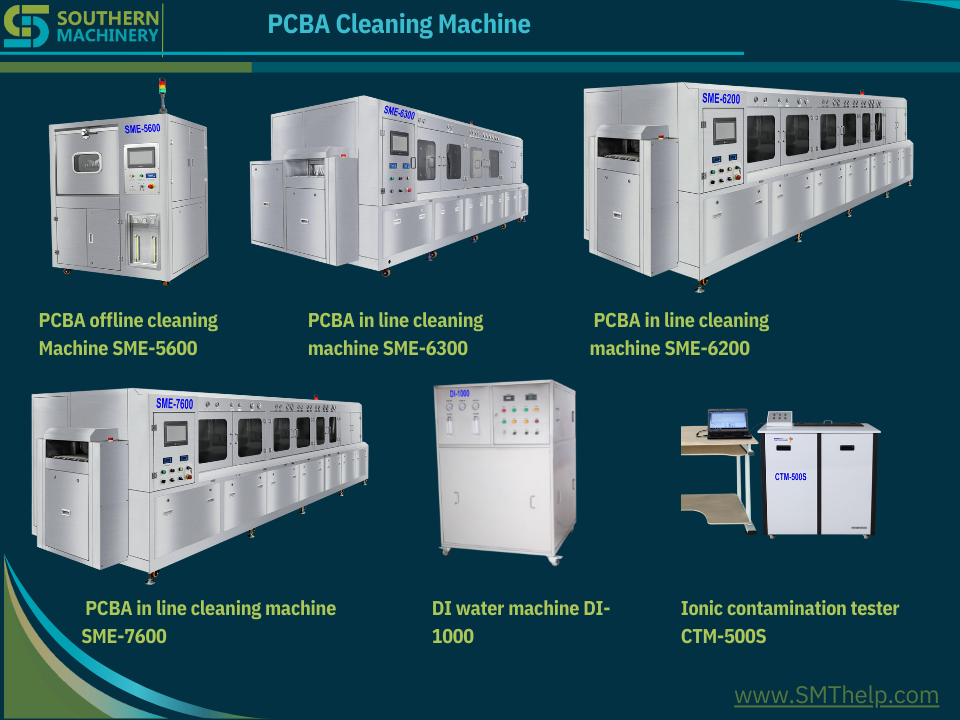
One article to understand the important trend of circuit board cleaning entering a new era of water-based cleaning
Keyword guide: circuit board cleaning, circuit board cleaning, PCBA circuit board cleaning, PCBA circuit board cleaning, solvent cleaning agent, water-based cleaning agent, water-based cleaning technology
Before discussing the question of “why use water-based cleaners for PCBA circuit board cleaning”, let’s take a look at the advantages and disadvantages of solvent-based cleaners.

Organic solvent cleaning agents can be divided into flammable cleaning agents and non-flammable cleaning agents according to their safety performance. The former are mainly organic hydrocarbons, alcohols and esters, and the latter are mainly chlorinated hydrocarbons and fluorinated hydrocarbons. Its process characteristics are introduced as follows:
- H FC / H C FC: the main component is chlorofluorocarbons containing hydrogen, the advantages are good volatility, fast drying speed after PCBA cleaning, the disadvantages are relatively high price, weak cleaning ability, not environmentally friendly, and will produce atmospheric ozone layer. Destructive effect, future use will be limited.
- Chlorinated hydrocarbons: The main representative substances are dichloromethane, trichloroethane, etc., which have strong ability to clean grease pollutants, are non-flammable and explosive, and are safe to use. The disadvantages are high toxicity, poor compatibility with plastics and rubber, easy corrosion of circuit boards, and poor stability of such substances.
- Hydrocarbons: mainly hydrocarbons, such as gasoline, kerosene, etc. Hydrocarbons have strong cleaning ability to grease pollutants. Due to low surface tension, they have a good cleaning effect on PCBA cracks, do not corrode metals, have low toxicity and are easy to use. The main disadvantage is that due to flammable and explosive, there are potential safety hazards, strict precautions must be taken.
- Alcohols: such as methanol, ethanol and isopropanol, alcohols have strong dissolving ability to polar pollutants, good cleaning effect on rosin, but difficult to clean grease pollutants; not easy to corrode metals and plastics, etc., and dry quickly. The disadvantage is that it is volatile, easy to burn, and has potential safety hazards in use.
If we take advantage of the advantages and disadvantages of organic solvent cleaning and avoid the disadvantages, wouldn’t it be perfect? Is it feasible? The answer is yes! Water-based cleaners were born around solving this problem.
Water-based cleaning technology is made of water as the cleaning medium, and various additives such as surfactants, solvents, defoaming agents, and corrosion inhibitors are added, and various pollutants are removed through various mechanisms such as dissolution, adsorption, and infiltration.
The main features of the water cleaning process are non-flammable and explosive, non-toxic and environmentally friendly, safe in operation, strong in cleaning ability, low in loss during cleaning, and low in cost. Because of the large degree of freedom of active ingredients, the formula can be formulated according to the special requirements of PCBA, which solves many problems. The problems that cannot be solved by organic solvent cleaning agents have a wide cleaning range and strong applicability. The flexible components of water-based cleaning agents can greatly meet the needs of customers, especially when ultrasonic cleaning and spray cleaning are used, they are more advantageous than organic solvents. .
Of course, water-based cleaning agents also have shortcomings, such as high requirements for cleaning equipment, and the need to treat invalid cleaning agents, that is, waste water.
Combining the characteristics of solvent-based cleaning agents and water-based cleaning agents, it is not difficult to find that with the strengthening of safety and environmental protection awareness and the increase of special cleaning needs for PCBA, water-based cleaning agents stand out because of their flexible formulas and components, representing the future of PCBA cleaning. Technology development direction.
3D SMT machine model for better training and evaluation
We understand that SMT machine training and after sales service are a key to choose a new supplier.
Please click below links to see machine 3D models:
https://www.smthelp.net/html/SMT Production line.html https://www.smthelp.net/html/THT_Auto_Insertion_full_line.html
SMT AI Peripheral Equipments and Spare parts
| Item | Product Name | URL |
| 1 | Bicycle | https://www.smthelp.net/html/Bicycle.html |
| 2 | FUJI_NXT_8mmfeeder | https://www.smthelp.net/html/FUJI_NXT_8mmfeeder.html |
| 3 | IC_tube_to_reeltapepackingmachine | https://www.smthelp.net/html/IC_tube_to_reeltapepackingmachine.html |
| 4 | PCBA_THT_fixture | https://www.smthelp.net/html/PCBA_THT_fixture.html |
| 5 | RS-1_Vibration_tube_FEEDER_BANK | https://www.smthelp.net/html/RS-1_Vibration_tube_FEEDER_BANK.html |
| 6 | SMT Label feeder.htm | https://www.smthelp.net/html/SMT Label feeder.htm |
| 7 | SMT reel tape feeder 72mm width | https://www.smthelp.net/html/SMT reel tape feeder 72mm width.html |
| 8 | SMT_axial_Radial_feeder_bank | https://www.smthelp.net/html/SMT_axial_Radial_feeder_bank.html |
| 9 | SMT_label_mounter | https://www.smthelp.net/html/SMT_label_mounter.html |
| 10 | SMT_Odd_Bowl_feeder | https://www.smthelp.net/html/SMT_Odd_Bowl_feeder.html |
| 11 | SMT_tray_feeder_B | https://www.smthelp.net/html/SMT_tray_feeder_B.html |
| 12 | SMThelp_PCBA-smt | https://www.smthelp.net/html/SMThelp_PCBA-smt.html |
| 13 | UIC_autoinsertion_Spareparts_list | https://www.smthelp.net/html/UIC_autoinsertion_Spareparts_list.html |
| 14 | wave_soldering_line | https://www.smthelp.net/html/wave_soldering_line.html |
| 15 | Wave soldering machine | https://www.smthelp.net/html/Wave soldering machine.html |
| 16 | Adapter JUKI Nozzle with Nozzle | https://www.smthelp.net/html/Adapter JUKI Nozzle with Nozzle.html |
| 17 | Auto Insertion Axial Radial Oddform Production line | https://www.smthelp.net/html/Auto Insertion Axial Radial Oddform Production line.html |
| 18 | Bowl Radial reel feeder w JUKI cart | https://www.smthelp.net/html/Bowl Radial reel feeder w JUKI cart.html |
| 19 | Conveyor 1M nolight | https://www.smthelp.net/html/Conveyor 1M nolight.html |
| 20 | Feeder cart-Bowl Axial Radial Tube | https://www.smthelp.net/html/Feeder cart-Bowl Axial Radial Tube.html |
| 21 | FUJI glue nozzle | https://www.smthelp.net/html/FUJI glue nozzle.html |
| 22 | FUJI nozzle WGW-CZ | https://www.smthelp.net/html/FUJI nozzle WGW-CZ.html |
| 23 | FUJI nozzle WJH-CZ | https://www.smthelp.net/html/FUJI nozzle WJH-CZ.html |
| 24 | fuji NXT 8mm feeder | https://www.smthelp.net/html/fuji NXT 8mm feeder.html |
| 25 | fuji NXT 8mm feeder | https://www.smthelp.net/html/fuji NXT 8mm feeder.html |
| 26 | FUJI Sfab Radial tape feeder | https://www.smthelp.net/html/FUJI Sfab Radial tape feeder.html |
| 27 | Gripper nozzle for E-cap | https://www.smthelp.net/html/Gripper nozzle for E-cap.html |
| 28 | Hign end conveyor 1M w PCBA | https://www.smthelp.net/html/Hign end conveyor 1M w PCBA.html |
| 29 | JUKI 2 layer bowl feeder w cart | https://www.smthelp.net/html/JUKI 2 layer bowl feeder w cart.html |
| 30 | JUKI Gripper_Nozzle 2583 C | https://www.smthelp.net/html/JUKI Gripper_Nozzle 2583 C.html |
| 31 | Juki Nozzle 500 Assembly | https://www.smthelp.net/html/Juki Nozzle 500 Assembly.html |
| 32 | Juki Nozzle 500 Head Assembly | https://www.smthelp.net/html/Juki Nozzle 500 Head Assembly.html |
| 33 | JUKI Radial tape feeder big span | https://www.smthelp.net/html/JUKI Radial tape feeder big span.html |
| 34 | JUKI Radial tape L lead feeder | https://www.smthelp.net/html/JUKI Radial tape L lead feeder .html |
| 35 | Juki2050 Feeder Cart w Radial axial | https://www.smthelp.net/html/Juki2050 Feeder Cart w Radial axial.html |
| 36 | Mobile charger PCBA | https://www.smthelp.net/html/Mobile charger PCBA.html |
| 37 | Nozzle adepter | https://www.smthelp.net/html/Nozzle adepter.html |
| 38 | Nozzle base | https://www.smthelp.net/html/Nozzle base.html |
| 39 | Odd form insertion Feeders w loader-unloader | https://www.smthelp.net/html/Odd form insertion Feeders w loader-unloader.html |
| 40 | Panasonic Al Spare parts list 2 | https://www.smthelp.net/html/Panasonic Al Spare parts list 2.html |
| 41 | Panasonic CM602 Bowl feeder | https://www.smthelp.net/html/Panasonic CM602 Bowl feeder.html |
| 42 | PCB Combo loader destacker+Magazine | https://www.smthelp.net/html/PCB Combo loader destacker+Magazine.html |
| 43 | PCB Magazine | https://www.smthelp.net/html/PCB Magazine.html |
| 44 | Power supplier | https://www.smthelp.net/html/Power supplier.html |
| 45 | Radial Cutter clinch head | https://www.smthelp.net/html/Radial Cutter clinch head.html |
| 46 | Radial Insertion Head Assy w Ecap | https://www.smthelp.net/html/Radial Insertion Head Assy w Ecap.html |
| 47 | RS-1 FEEDER BANK w Vibe tube feeder | https://www.smthelp.net/html/RS-1 FEEDER BANK w Vibe tube feeder.html |
| 48 | S3010A Radial Insertion machine inline | https://www.smthelp.net/html/S3010A Radial Insertion machine inline.html |
| 49 | S3010A Radial machine no cover | https://www.smthelp.net/html/S3010A Radial machine no cover.html |
| 50 | S7000 Odd Form Insertion machine | https://www.smthelp.net/html/S7000 Odd Form Insertion machine.html |
| 51 | S7000 Oddform insertion 3 bowl feeder | https://www.smthelp.net/html/S7000 Oddform insertion 3 bowl feeder.html |
| 52 | S700D Odd Form Insertion machine | https://www.smthelp.net/html/S700D Odd Form Insertion machine.html |
| 53 | S-7020T Terminal insertion | https://www.smthelp.net/html/S-7020T Terminal insertion.html |
| 54 | S-7040 Oddform insertion w 4 bowl feeder | https://www.smthelp.net/html/S-7040 Oddform insertion w 4 bowl feeder.html |
| 55 | S-7040T Oddform insertion w Tray feeder | https://www.smthelp.net/html/S-7040T Oddform insertion w Tray feeder.html |
| 56 | SBH250 NGOK dual nagazine PCB unloader w magazine | https://www.smthelp.net/html/SBH250 NGOK dual nagazine PCB unloader w magazine.html |
| 57 | SBU460 Bare PCB destacker loader +conveyor | https://www.smthelp.net/html/SBU460 Bare PCB destacker loader +conveyor.html |
| 58 | SLD250 PCB loader w magazine | https://www.smthelp.net/html/SLD250 PCB loader w magazine.html |
| 59 | SLD250 S4020A+S3010A SULD250 Al machine production line | https://www.smthelp.net/html/SLD250 S4020A+S3010A SULD250 Al machine production line.html |
| 60 | SLD250+ S3020A +SULD250 Radial Insertion machine inline | https://www.smthelp.net/html/SLD250+ S3020A +SULD250 Radial Insertion machine inline.html |
| 61 | SLD250+S3010A(s)+SULD250 Al machine production line | https://www.smthelp.net/html/SLD250+S3010A(s)+SULD250 Al machine production line.html |
| 62 | SLD250+S3010A+S7040T(tray feeder)+SULD250 Al machine production line | https://www.smthelp.net/html/SLD250+S3010A+S7040T(tray feeder)+SULD250 Al machine production line.html |
| 63 | SLD390 SMT PCB loader (L-R) | https://www.smthelp.net/html/SLD390 SMT PCB loader (L-R).html |
| 64 | SLD390L SMT PCB loader(L-R) | https://www.smthelp.net/html/SLD390L SMT PCB loader(L-R).html |
| 65 | SLD390L SMT PCB loader(L-R)w magazine | https://www.smthelp.net/html/SLD390L SMT PCB loader(L-R)w magazine.html |
| 66 | SLVC200 Vacuum PCB loader +conveyor | https://www.smthelp.net/html/SLVC200 Vacuum PCB loader +conveyor.html |
| 67 | SLVC200 Vacuum PCB loader | https://www.smthelp.net/html/SLVC200 Vacuum PCB loader.html |
| 68 | SMT 2 rail bowl feeder | https://www.smthelp.net/html/SMT 2 rail bowl feeder.html |
| 69 | SMT BHS line1 | https://www.smthelp.net/html/SMT BHS line1.html |
| 70 | SMT CART FEEDER | https://www.smthelp.net/html/SMT CART FEEDER.html |
| 71 | SMT customized nozzle design n manufacturing | https://www.smthelp.net/html/SMT customized nozzle design n manufacturing.html |
| 72 | SMT Drone main control board | https://www.smthelp.net/html/SMT Drone main control board.html |
| 73 | SMT Gripper nozzle customized | https://www.smthelp.net/html/SMT Gripper nozzle customized.html |
| 74 | SMT Gripper nozzle JUKI | https://www.smthelp.net/html/SMT Gripper nozzle JUKI.html |
| 75 | SMT label feeder | https://www.smthelp.net/html/SMT label feeder.html |
| 76 | SMT nozzle list 1 | https://www.smthelp.net/html/SMT nozzle list 1.html |
| 77 | SMT Nozzle MiniChuck_closing w component | https://www.smthelp.net/html/SMT Nozzle MiniChuck_closing w component.html |
| 78 | SMT PCB 90 turn conveyor | https://www.smthelp.net/html/SMT PCB 90 turn conveyor.html |
| 79 | SMT PCB conveyor 1M w lighting | https://www.smthelp.net/html/SMT PCB conveyor 1M w lighting.html |
| 80 | SMT PCB Flipper (turn over) + conveyor w PCBA | https://www.smthelp.net/html/SMT PCB Flipper (turn over) + conveyor w PCBA.html |
| 81 | SMT PCB Flipper (turn over) conveyor | https://www.smthelp.net/html/SMT PCB Flipper (turn over) conveyor.html |
| 82 | SMT PCB Shuttle conveyor | https://www.smthelp.net/html/SMT PCB Shuttle conveyor.html |
| 83 | SMT PnP mounter | https://www.smthelp.net/html/SMT PnP mounter.html |
| 84 | SMT Production line | https://www.smthelp.net/html/SMT Production line.html |
| 85 | SMT reflow oven | https://www.smthelp.net/html/SMT reflow oven.html |
| 86 | SMT Screen printer | https://www.smthelp.net/html/SMT Screen printer.html |
| 87 | SMT THT bare PCB board | https://www.smthelp.net/html/SMT THT bare PCB board.html |
| 88 | SMT THT DC Power PCBA | https://www.smthelp.net/html/SMT THT DC Power PCBA.html |
| 89 | SMT tray feeder -B | https://www.smthelp.net/html/SMT tray feeder -B.html |
| 90 | SMT Tray feeder | https://www.smthelp.net/html/SMT Tray feeder.html |
| 91 | SMT tube feeder | https://www.smthelp.net/html/SMT tube feeder.html |
| 92 | SMT Vacuum Nozzle 505 | https://www.smthelp.net/html/SMT Vacuum Nozzle 505.html |
| 93 | SMThelp Axial taped feeder | https://www.smthelp.net/html/SMThelp Axial taped feeder.html |
| 94 | SMThelp PCB BHS production line | https://www.smthelp.net/html/SMThelp PCB BHS production line.html |
| 95 | SMThelp PCB Magazine w PCBA | https://www.smthelp.net/html/SMThelp PCB Magazine w PCBA.html |
| 96 | SMThelp PCBA 2 in 1 | https://www.smthelp.net/html/SMThelp PCBA 2 in 1.html |
| 97 | SMThelp SMT-THT pcba 8in1 | https://www.smthelp.net/html/SMThelp SMT-THT pcba 8in1.html |
| 98 | SMThelp THT pcb assembly 9in1 | https://www.smthelp.net/html/SMThelp THT pcb assembly 9in1.html |
| 99 | SMThelp THT pcba | https://www.smthelp.net/html/SMThelp THT pcba.html |
| 100 | SULD250 PCB Unloader (R-L) | https://www.smthelp.net/html/SULD250 PCB Unloader (R-L).html |
| 101 | SULD390 PCB Unloader (L-R) | https://www.smthelp.net/html/SULD390 PCB Unloader (L-R).html |
| 102 | SULD390 PCB Unloader (R-L) w Magazine | https://www.smthelp.net/html/SULD390 PCB Unloader (R-L) w Magazine.html |
| 103 | SULD390 PCB Unloader (R-L) | https://www.smthelp.net/html/SULD390 PCB Unloader (R-L).html |
| 104 | SULD390 PCB Unloader (R-L) | https://www.smthelp.net/html/SULD390 PCB Unloader (R-L).html |
| 105 | SULD460 L-type PCB unloader (L-R) | https://www.smthelp.net/html/SULD460 L-type PCB unloader (L-R).html |
| 106 | THT axial radial PCBA | https://www.smthelp.net/html/THT axial radial PCBA.html |
| 107 | THT Capacitor lead cut-forming | https://www.smthelp.net/html/THT Capacitor lead cut-forming.html |
| 108 | Tray feeder w feeder bank | https://www.smthelp.net/html/Tray feeder w feeder bank.html |
| 109 | Tray feeder | https://www.smthelp.net/html/Tray feeder.html |
| 110 | UIC BHS Assy | https://www.smthelp.net/html/UIC BHS Assy.html |
| 111 | UIC FJ head assy | https://www.smthelp.net/html/UIC FJ head assy.html |
| 112 | UIC Radial Carrier Clip | https://www.smthelp.net/html/UIC Radial Carrier Clip.html |
| 113 | UIC Radial Feeder and Carrier Clip (1) | https://www.smthelp.net/html/UIC Radial Feeder and Carrier Clip (1).html |
| 114 | UIC Radial lead component carrier clip w Ecap | https://www.smthelp.net/html/UIC Radial lead component carrier clip w Ecap.html |
| 115 | UIC Radial lead component carrier clip | https://www.smthelp.net/html/UIC Radial lead component carrier clip.html |
| 116 | UIC spare parts list 3 | https://www.smthelp.net/html/UIC spare parts list 3.html |
| 117 | wave soldering line | https://www.smthelp.net/html/wave soldering line.html |
| 118 | Wave soldering output conveyor | https://www.smthelp.net/html/Wave soldering output conveyor.html |
| 119 | What is SMT Gripper nozzle | https://www.smthelp.net/html/What is SMT Gripper nozzle.html |
| 120 | What is SMT Gripper nozzle | https://www.smthelp.net/html/What is SMT Gripper nozzle.html |
| 121 | X_Y_workingtable | https://www.smthelp.net/html/X_Y_workingtable.html |
| 122 | Yamaha nozzle YMH-100ll-31 | https://www.smthelp.net/html/Yamaha nozzle YMH-100ll-31.html |
| 123 | Yamaha nozzle YMH-100ll-31 | https://www.smthelp.net/html/Yamaha nozzle YMH-100ll-31.html |
| 124 | Yamaha nozzleYMH-112-52 | https://www.smthelp.net/html/Yamaha nozzleYMH-112-52.html |
| 125 | Yamaha nozzleYMH-112-52 | https://www.smthelp.net/html/Yamaha nozzleYMH-112-52.html |
| 126 | Ymaha nozzle YMH-112-52 | https://www.smthelp.net/html/Ymaha nozzle YMH-112-52.html |
| 127 | Ymaha nozzle YMH-112-52 | https://www.smthelp.net/html/Ymaha nozzle YMH-112-52.html |
| 128 | Auto Tray n Tube stick feeder with Robot platform | https://www.smthelp.net/html/Auto Tray n Tube stick feeder with Robot platform.html |
THT production line:
| Item | Product Name | URL |
| 1 | S3010A Radial Insertion Machine | https://www.smthelp.net/html/S3010A Radial Insertion Machine.html |
| 2 | S7000P Pin Eyelet Inserter w loader | https://www.smthelp.net/html/S7000P Pin Eyelet Inserter w loader.html |
| 3 | S4000H JW Axial Insertion machine w loader | https://www.smthelp.net/html/S4000H JW Axial Insertion machine w loader.html |
| 4 | THT Auto Insertion full line | https://www.smthelp.net/html/THT_Auto_Insertion_full_line.html |
| 5 | wave soldering line | https://www.smthelp.net/html/wave soldering line.html |
| 6 | Xy workingtable | https://www.smthelp.net/html/X_Y_workingtable.html |
| 7 | PIN Eyelet Odd inserter | https://www.smthelp.net/html/PIN_Eyelet_Odd_inserter.html |
| 8 | S7000T Reel tape terminal inserter w PCB loading | https://www.smthelp.net/html/S7000T Reel tape terminal inserter w PCB loading.html |
| 9 | Manual Assembly line | https://www.smthelp.net/html/Manual Assembly line.html |
| 10 | Terminal PIN Eyelet Inserter 2 headbowl PCB | https://www.smthelp.net/html/Terminal_PIN_Eyelet_Inserter_2_head_bowl_PCB.html |
| 11 | S-7020TTerminalinsertion | https://www.smthelp.net/html/S-7020T_Terminal_insertion.html |
| 12 | S7000T Reeltape terminal inserter w PCB loading | https://www.smthelp.net/html/S7000T_Reel_tape_terminal_inserter_w_PCB loading.html |
| 13 | S7040 Oddform Insertion machine x2 w F-B feeders PCB loading | https://www.smthelp.net/html/S7040 Oddform Insertion machine x2 w F-B feeders PCB loading.html |
| 14 | S7040 Oddform Insertion machine x2 w Front feeders | https://www.smthelp.net/html/S7040 Oddform Insertion machine x2 w Front feeders.html |
| 15 | S7040 OddFrom Insertion Machine w feeder PCB loading | https://www.smthelp.net/html/S7040 OddFrom Insertion Machine w feeder PCB loading.html |
| 16 | S7040 Oddform Insertion machine w Front feeders | https://www.smthelp.net/html/S7040 Oddform Insertion machine w Front feeders.html |
| 17 | Manual assemble line 2 | https://www.smthelp.net/html/Manual assemble line 2.html |
| 18 | S3010A Radial Insertion Machine w PCB loader inloader | https://www.smthelp.net/html/S3010A Radial Insertion Machine w PCB loader inloader.html |
| 19 | Wave Soldering machine and Manual assemble line 2 | https://www.smthelp.net/html/Wave Soldering machine and Manual assemble line 2.html |
| 20 | S7040 Oddform Insertion machine | https://www.smthelp.net/html/S7040 Oddform Insertion machine.html |
| 21 | SLD250 PCB Magazine Loader (250mm) w PCB | https://www.smthelp.net/html/SLD250 PCB Magazine Loader (250mm) w PCB.html |
| 22 | S3010A Radial Insertion machine inline | https://www.smthelp.net/html/S3010A Radial Insertion machine inline.html |
| 23 | SLD250 S3020ASULD250 Radial Insertion machine inline | https://www.smthelp.net/html/SLD250+%20S3020A%20+SULD250%20Radial%20Insertion%20machine%20inline.html |
SMT production line:
| Item | Product Name | URL |
| 1 | Mutil Line shuttle to 3 oven | https://www.smthelp.net/html/Mutil Line shuttle to 3 oven.html |
| 2 | Reflow Oven 8 zones | https://www.smthelp.net/html/Reflow Oven 8 zones.html |
| 3 | SMT loader Printer SPI NXT M3x4 (R-L) | https://www.smthelp.net/html/SMT loader Printer SPI NXT M3x4 (R-L).html |
| 4 | SMT Line Loader DEK SPI NXT | https://www.smthelp.net/html/SMT Line Loader DEK SPI NXT.html |
| 5 | SMTLineLoaderDEKSPINXT | https://www.smthelp.net/html/SMTLineLoaderDEKSPINXT.html |
| 6 | SMT_mounter | https://www.smthelp.net/html/SMT_mounter.html |
| 7 | PCBA Manual assembly with Wave Soldering machine line | https://www.smthelp.net/html/PCBA Manual assembly with Wave Soldering machine line.html |
| 8 | SMT Line L-R loader printer SPI mounter | https://www.smthelp.net/html/SMT Line L-R loader printer SPI mounter.html |
| 9 | DEK Printer | https://www.smthelp.net/html/DEK Printer.html |
| 10 | AOI with NGOK Unloader | https://www.smthelp.net/html/AOI with NGOK Unloader.html |
| 11 | NG Buffer 1M | https://www.smthelp.net/html/NG Buffer 1M.html |
| 12 | SMTtrayfeederwpickuphead | https://www.smthelp.net/html/SMTtrayfeederwpickuphead.html |
| 13 | Dual Magazine Unloader | https://www.smthelp.net/html/Dual Magazine Unloader.html |
| 14 | DualMagazineUnloader | https://www.smthelp.net/html/DualMagazineUnloader.html |
| 15 | SMT Mounter | https://www.smthelp.net/html/SMT Mounter.html |
| 16 | SMT Mounter.sync-conflict-20220307-122016-RCA3U2I | https://www.smthelp.net/html/SMT Mounter.sync-conflict-20220307-122016-RCA3U2I.html |
| 17 | PCB NG Buffer conveyor 0.8M length 460mm width | https://www.smthelp.net/html/PCB NG Buffer conveyor 0.8M length 460mm width.html |
| 18 | S350DLC_1Mconveyorwithlightingcooling | https://www.smthelp.net/html/S350DLC_1Mconveyorwithlightingcooling.html |
| 19 | PCB Buffer with cooling L-R 1M | https://www.smthelp.net/html/PCB Buffer with cooling L-R 1M.html |
| 20 | PCB NGOK Unloader | https://www.smthelp.net/html/PCB NGOK Unloader.html |
| 21 | Dual line Unloader | https://www.smthelp.net/html/Dual line Unloader.html |
| 22 | PCB Magazine and Vacuum combo loader w PCB | https://www.smthelp.net/html/PCB Magazine and Vacuum combo loader w PCB.html |
| 23 | SLD250 PCB Magazine Loader (250mm) | https://www.smthelp.net/html/SLD250 PCB Magazine Loader (250mm).html |
| 24 | PCB Magazine and Vacuum combo loader | https://www.smthelp.net/html/PCB Magazine and Vacuum combo loader.html |
| 25 | Dual line shuttle to Dual rail oven | https://www.smthelp.net/html/Dual line shuttle to Dual rail oven.html |
| 26 | SMT production line std | https://www.smthelp.net/html/SMT production line std.html |
| 27 | SMT product line 1 | https://www.smthelp.net/html/SMT product line 1.html |
| 28 | Dual rail Oven Buffer AOI Unloader | https://www.smthelp.net/html/Dual rail Oven Buffer AOI Unloader.html |
| 29 | Mutil Line NXT shuttle to 1 oven.htm | https://www.smthelp.net/html/Mutil Line NXT shuttle to 1 oven.htm |
| 30 | SMT production line loader printer mounter | https://www.smthelp.net/html/SMT production line loader printer mounter.html |
| 31 | SMT production line loader printer mounter R-L | https://www.smthelp.net/html/SMT production line loader printer mounter R-L.html |
| 32 | SMT product line Printer Mounter Over w loader magazine | https://www.smthelp.net/html/SMT product line Printer Mounter Over w loader magazine.html |
| 33 | SMTvacuumnozzl | https://www.smthelp.net/html/SMTvacuumnozzl.html |
| 34 | Wave soldering machine | https://www.smthelp.net/html/Wave soldering machine.html |
| 35 | LED-mounter_semiauto | https://www.smthelp.net/html/LED-mounter_semiauto.html |
| 36 | UIC FJ 7 head assy | https://www.smthelp.net/html/UIC FJ 7 head assy.html |
| 37 | SMT tube feeder | https://www.smthelp.net/html/SMT tube feeder.html |
| 38 | Desktop SMT pick n place mounter | https://www.smthelp.net/html/Desktop SMT pick n place mounter.html |
| 39 | DesktopSMTpicknplacemounter | https://www.smthelp.net/html/DesktopSMTpicknplacemounter.html |
| 40 | SMTreeltapefeeder | https://www.smthelp.net/html/SMTreeltapefeeder.html |
| 41 | SMT shuttle machine | https://www.smthelp.net/html/SMT shuttle machine.html |
| 42 | Wave soldering input conveyor | https://www.smthelp.net/html/Wave soldering input conveyor.html |
| 43 | SMT placement head 6 nozzles | https://www.smthelp.net/html/SMT placement head 6 nozzles.html |
| 44 | SMT UIC IL 4 head base assy | https://www.smthelp.net/html/SMT UIC IL 4 head base assy.html |
| 45 | Magazine S | https://www.smthelp.net/html/Magazine S.html |
| 46 | SMT Label feeder | https://www.smthelp.net/html/SMT Label feeder.html |
| 47 | Manual assemble line 2 | https://www.smthelp.net/html/Manual assemble line 2.html |
| 48 | SMTLabelfeeder | https://www.smthelp.net/html/SMTLabelfeeder.html |
| 49 | PCB NG Buffer conveyor 0.8M length 460mm width.htm | https://www.smthelp.net/html/PCB NG Buffer conveyor 0.8M length 460mm width.htm |
| 50 | Radial Feeder | https://www.smthelp.net/html/Radial Feeder.html |
| 51 | PCBflipperconveyor | https://www.smthelp.net/html/PCBflipperconveyor.html |
| 52 | PCB flipper conveyor | https://www.smthelp.net/html/PCB flipper conveyor.html |
| 53 | RadialFeeder | https://www.smthelp.net/html/RadialFeeder.html |
| 54 | Wave soldering output conveyor | https://www.smthelp.net/html/Wave soldering output conveyor.html |
| 55 | SMTAxialFeeder | https://www.smthelp.net/html/SMTAxialFeeder.html |
| 56 | SMT reel tape feeder 72mm width | https://www.smthelp.net/html/SMT reel tape feeder 72mm width.html |
| 57 | S350C Conveyor 1M | https://www.smthelp.net/html/S350C Conveyor 1M.html |
| 58 | SMT_smalltubefeeder | https://www.smthelp.net/html/SMT_smalltubefeeder.html |
| 59 | Desktop robot soldering machine | https://www.smthelp.net/html/Desktop robot soldering machine.html |
| 60 | SMT GKG Printer | https://www.smthelp.net/html/SMT GKG Printer.html |
| 61 | SMTGrippernozzle | https://www.smthelp.net/html/SMTGrippernozzle.html |
| 62 | FUJI NXT M3 Mounter | https://www.smthelp.net/html/FUJI NXT M3 Mounter.html |
| 63 | AOI machine | https://www.smthelp.net/html/AOI machine.html |
| 64 | SMT PCB Loader Flipper (turn over) + conveyor w PCBA | https://www.smthelp.net/html/SMT PCB Loader Flipper (turn over) + conveyor w PCBA.html |
| 65 | SMT PCB Flipper (turn over)conveyor w PCBA | https://www.smthelp.net/html/SMT PCB Flipper (turn over)conveyor w PCBA.html |
| 66 | SMT PCB Flipper (turn over) conveyor | https://www.smthelp.net/html/SMT PCB Flipper (turn over) conveyor.html |
A difference between Electric Stencil Cleaner(SME-800) and Pneumatic Stencil Cleaner(SME-750)


Comparison list
[embeddoc url=”https://www.smthelp.net/wp-content/uploads/2020/11/A-difference-between-SME-800-Electric-Stencil-Cleaner-and-SME-750-Pneumatic-Stencil-Cleaner-1.doc” download=”all” viewer=”microsoft”]
3D SMT machine drawing supporting Smart EMS factory
The unit loads your production line automatically by pushing PCB’s out of a magazine onto the conveyor of the down-stream machine
[embeddoc url=”https://www.smthelp.net/wp-content/uploads/2020/07/SMThelp-PCB-Conveyor-3D.pptx” download=”all” viewer=”microsoft”]
3D RS-1 Vibration Feeder
3D SMT PCB conveyor
3D SMT PCB Magazine
3D Southern Machinery logo
3D UIC Radial taped feeder housing
3D JUKI Gripper nozzle
How to make SMT stencil by Laser cutting machine for EMS factory
[embeddoc url=”https://www.smthelp.net/wp-content/uploads/2020/05/SMT-stencil-laser-making-machine.pdf” download=”all”]SMT stencil production process (reference)
General technical requirements:
1. Screen frame: The frame size is determined according to the requirements of the printing machine. Taking DEK265 and MPM UP 3000 as an example, the frame size is 29ˊ
29ˊ, using aluminum alloy, frame profile specification is 1.5ˊ 1.5ˊ.
- Stretching the net: Adopt the red glue + aluminum tape method, at the junction of the aluminum frame and the glue, a layer of protective paint must be evenly scraped. At the same time, in order to ensure that the screen has sufficient tension and good flatness, it is recommended that the stainless steel plate be kept 25mm-50mm away from the inside of the screen frame.
-
Reference point: According to the size and shape provided by the PCB information, the opening is 1: 1, and the translucent is engraved on the reverse side of the printing. At the corresponding coordinates, the entire PCB opens at least two reference points.
-
Opening requirements: 1.41. The position and size ensure a high opening accuracy, and the opening is strictly in accordance with the prescribed opening method. 1.42. The size of the independent opening cannot be too large, the width cannot be greater than 2mm, and a 0.4mm bridge is required in the middle of the pad size greater than 2mm, so as not to affect the strength of the stencil.
1.43. The opening area must be centered. -
Characters: In order to facilitate production, it is recommended to engrave the following characters in the lower left or lower right corner of the screen: Model; T; Date; the name of the company that made the screen.
-
Stencil thickness: In order to ensure the amount of solder paste printing and welding quality, the surface of the stencil is smooth and even, and the thickness is uniform. The stencil thickness refers to the above table. The stencil thickness should meet the premise of the finest pitch QFP BGA. If there are 0.5mmQFP and CHIP 0402 components on the PCB, the stencil thickness is 0.12mm; if there are 0.5mmQFP and CHIP 0603 or more components on the PCB, the stencil thickness is 0.15mm;
The opening shape and size requirements of printed tin screen:
- General principle: According to the requirements of the IPC-7525 steel mesh design guide, in order to ensure that the solder paste can be smoothly released from the opening of the stencil to the PCB pad, in the opening of the stencil to view polyester 1. The area ratio / width-to-thickness ratio area ratio is greater than 0.66 2. The mesh hole wall is smooth. Especially for QFP and CSP with a pitch of less than 0.5mm, suppliers are required to perform electro-polishing during the manufacturing process. 3.) With the printing surface as the upper side, the lower opening of the mesh opening should be 0.01mm or 0.02mm wider than the upper opening, that is, the opening is inverted tapered, which facilitates the ineffective release of solder paste and reduces the number of times of cleaning the stencil. Normally, the size and shape of the opening of the SMT element is the same as the pad, and the opening is 1: 1. Under special circumstances, for some special SMT components, the size and shape of the screen openings are specified.
No. 2 Special SMT component screen opening:
2.1CHIP components: CHIP components above 0603, in order to effectively prevent the generation of tin beads.
2.2SOT89 components: Due to the large pad and small pad spacing between components, soldering quality problems such as tin beads are prone to occur.
2.3 SOT252 component: Because SOT252 has a large pad, it is easy to produce tin beads, and the reflow soldering tension causes displacement.
Look 2.4IC: A. For the standard pad design, PITCH》 = 0.65mm IC, the opening width is 90% of the pad width, and the length is unchanged.
B. For the standard pad design, IC with PITCH <= 005mm, because of its small PITCH, it is easy to produce bridging, the length direction of the steel mesh opening is unchanged, the opening width is 0.5PITCH, and the opening width is 0.25mm.
2.5 Other situations: One pad is too large, usually one side is greater than 4mm, and the other side is not less than 2.5mm, in order to prevent the generation of tin beads and displacement caused by the effect of tension, the mesh opening is recommended to be divided by grid lines In this way, the grid line width is 0.5mm and the grid size is 2mm, which can be evenly divided according to the pad size.
The shape and size requirements of the opening of the printed rubber screen: glue is used for simple PCB assembly. Dispensing is preferred. CHIP, MELF, SOT components are printed through the screen, and IC is used to avoid glue scraping. Here, only the recommended opening size and opening shape of CHIP, MELF and SOT offset printing plates are given.
1. Two diagonal positioning holes must be opened at the diagonal of the stencil. Select FIDUCIAL MARK to open the hole.
- The openings are all elongated. Inspection method 1) Visually check that the opening is centered and the net is flat. 2) Check the correctness of the stencil opening through the PCB entity. 3) Examine the length and width of the screen opening and the smoothness of the hole wall and the surface of the steel sheet with a scaled high power microscope. 4) The thickness of the steel sheet is verified by detecting the thickness of the solder paste after printing tin, that is, the result verification. Conclusion The technical requirements for screen design have been tested for a period of time, and the print quality has been well controlled. The PPM of SMT welding quality has dropped from about 1300ppm to about 130ppm. Due to the development of the packaging direction of modern electronic components, higher requirements have also been placed on the design of steel mesh. Is a subject that we need to focus on in the future
How to layout EMS smart SMT production line for Industrial 4.0
Main content of lean factory design
The traditional way of plant layout begins with equipment and tooling, and finally considers the flow of processes. Unlike traditional factory layouts, lean factory design layout begins with the customer and then designs the process flow around the workforce.
Lean factory design should comprehensively apply the knowledge of lean production ideas, system engineering, enterprise management, etc., and use parallel technology, information technology and other means to determine the factory design plan that meets the requirements of lean production concept. The main design contents are as follows:
(1) Production line layout based on lean thinking
The design of the best production line must be independent of the current legacy workflow and should reduce or eliminate large amounts of moving time for products and materials. According to the assembly requirements, placing the part loading process on the assembly point where the material of the production line is consumed will reduce the movement and waiting time.
(2) Lean logistics system design
According to the lean production point of view, logistics is not a value-added link. Therefore, the goal of lean logistics system design is to minimize the logistics and strive to minimize the waste in the logistics process while meeting the production requirements. To break the limitations of the profession, try to set up and no intermediate inventory area, and completely follow the process flow layout. All ideas that minimize the amount of movement and optimize the flow of the product should be tested. Ultimately, a practical and appropriate approach should be taken to finalize the production line in order to maximize the benefits of the production process. .
(3) Lean selection and arrangement of equipment
It is necessary to fully consider the relationship between the various production links, and on the basis of realizing the capacity requirements, try to achieve a balanced production capacity and reflect the idea of lean flow. At the same time, the choice of equipment is not based on the most advanced standards, but the small size, low investment, flexibility and other indicators are put in the first place, in order to meet the needs of flexible production in the future.
(4) Lean staffing
Traditional factories use the “scheduled system” staffing, but this method increases the cost of the enterprise and reduces the response speed of the enterprise under the multi-variety and small-batch production methods. Lean factory design, it is recommended to use the least staff to achieve the same production needs, through the training of employees, so that it has a variety of skills, so that with the change in production, flexible arrangements for operators.
(5) Lean selection of auxiliary equipment
Although the fixtures and tools required for production assistance are not resource equipment, they must be considered for lean production. It must be designed to accommodate the movement of the required materials, such as the passage of the automatic loading and unloading trucks and large material containers. It is necessary to design the station to be more compact, but at the same time, the operator should be considered to be as ergonomic as possible.
In addition, the design of the lean factory should also include the planning of the public facilities of the factory, the design of the information system, etc., and should be carried out according to the specific needs of the factory and the actual situation of the enterprise.
The goal of lean plant design is to minimize waste and overload in the work process while enhancing visual communication on site.
How to remove the misprinted solder paste on the PCB surface?
How to remove the misprinted solder paste on the PCB surface?
Prepared by Ming
ming@smthelp.net
This article describes that paying attention to some details can often prevent common problems in assembly processes and equipment selection.

Question: Can I use a small spatula to remove misprinted solder paste from the board? Will this get the solder paste and small tin beads into the holes and small gaps?
Answer: Using a small spatula to remove the solder paste from the misprinted board may cause some problems. It is generally practicable to immerse the misprinted board in a compatible solvent, such as water with an additive, and then remove the small tin beads from the board with a soft brush. I prefer to soak and wash repeatedly instead of violent dry brush or shovel. After the solder paste is printed, the longer the operator waits to clean the misprint, the harder it is to remove the solder paste. Misprinted boards should be placed in the soaking solvent immediately after the problem is discovered, as the solder paste is easily removed before it is dried.
Avoid wiping with a strip of cloth to prevent solder paste and other contaminants from smearing on the surface of the board. After soaking, brushing with a gentle spray can often help remove unwanted tins. It is also recommended to dry with hot air. If a horizontal stencil cleaner is used, the side to be cleaned should face down to allow the solder paste to fall off the board.
As usual, note that some details can eliminate undesirable conditions, such as misprinting of the solder paste and removal of the solder paste from the board. It is our goal to deposit the right amount of solder paste at the desired location. Stained tools, dry solder paste, and misalignment of the stencils and plates can cause undesirable solder paste on the underside of the stencil or even the assembly. During the printing process, the template is wiped with a certain pattern between printing cycles. Ensure that the template is seated on the pad, not on the solder mask, to ensure a clean solder paste printing process. On-line, real-time solder paste inspection and inspection prior to reflow after component placement are process steps that reduce process defects prior to soldering.
For fine-pitch stencils, if damage is caused between pins due to thin stencil cross-section bending, it can cause solder paste to deposit between the pins, causing printing defects and/or short circuits. Low viscosity solder paste can also cause printing defects. For example, high operating temperatures or high blade speeds can reduce the stickiness of the solder paste during use, resulting in printing defects and bridging due to excessive solder paste deposition.
In general, the lack of adequate control of materials, solder paste deposition methods and equipment are the main causes of defects in the reflow soldering process.
Question: What type of assembly board depaneling equipment provides the best results?
Answer: There are several sub-board systems that offer a variety of techniques for slab assembly boards. As a rule, there are many factors that should be considered when selecting such a device. Regardless of whether there is routing, sawing or blanking to separate individual panels from the composite panel, stable support during the splitting process is the most important factor. Without support, the resulting stress can damage the substrate and solder joints. Distorting the plate, or stressing the assembly during the splitting, can result in hidden or significant defects. While sawing often provides minimal clearance, shearing or die cutting with tools can provide cleaner, more controlled results.
In order to avoid component damage, many assemblers attempt to maintain component solder joints at least 5.08 mm from the edge of the board when the splitter is required. Sensitive ceramic capacitors or diodes may require extra care and consideration.
1,Please visit : www.smthelp.net
2, Find us more: https://www.facebook.com/autoinsertion
3, Know more our team: https://www.linkedin.com/in/ming-gan118/
4, Welcome to our factory in Shenzhen China
5, See more video in Youtube: Auto+Insertion
6, Looking for more informations: ming@smthelp.net
7.Wechat/Whatsapp/skype:+86 18126316729
Related connections:
1. 3 minutes to complete a SMT stencil cleaning, improving the quality of your electronic products:S-1688 stencil-cleaning-machine
https://www.smthelp.net/product/pneumatic-stencil-cleaner-machine-s-1688

2.How to produce SMT high quality products? (for aviation, aerospace, medical products)pcba-cleaning-machine:
https://www.smthelp.net/product/pcba-cleaning-machine

