Wave Soldering Machine
User’s Manual

Model:
S-WS300
Be sure to carefully read this manual before use * to ensure proper use of the product
Chapter 2 Main Technical Indicators 4
Chapter 3 Wave soldering start-up instructions 5-6
Chapter 4 Interface Operation 7-12
Chapter 5 Installation Adjustment and Commissioning 13
Chapter 6 Inverter Description 18
Chapter 7 Spray Rosin Furnaces 18
Chapter 10 Maintenance and Precautions 25
Chapter 12 General Troubleshooting 27
Chapter 1 Overview
Automatic wave soldering machine is currently the mainstream of electronic products welding process, compared with other manual welding with a variety of manual, has unparalleled advantages, and thus widely used by electronics manufacturers. The automatic claw wave soldering machine produced by our company is the most advanced using modern high-tech technology.
The new design of crystallization:
(1) Unique automated preparation program;
(2) Perfect work/adjustment function;
(3) The temperature is controlled by the temperature control table of WINPARK. The speed is high and the precision is high. It is suitable for long-distance transmission in harsh industrial environments and has high reliability.
(4) The chain speed is controlled by the frequency conversion speed control motor, which is easy to adjust.
(5) Solder joints are of high quality, easy operation and good service. They are reliable products in this industry.
Thank you for your inquiry and use this machine, thank you very much! Before use, please read this manual carefully. It will provide you with all the functions of the machine thoroughly, and it will be fully utilized in production.
Chapter 2 Main Technical indicators
| PCB Size: Max.50~300mm |
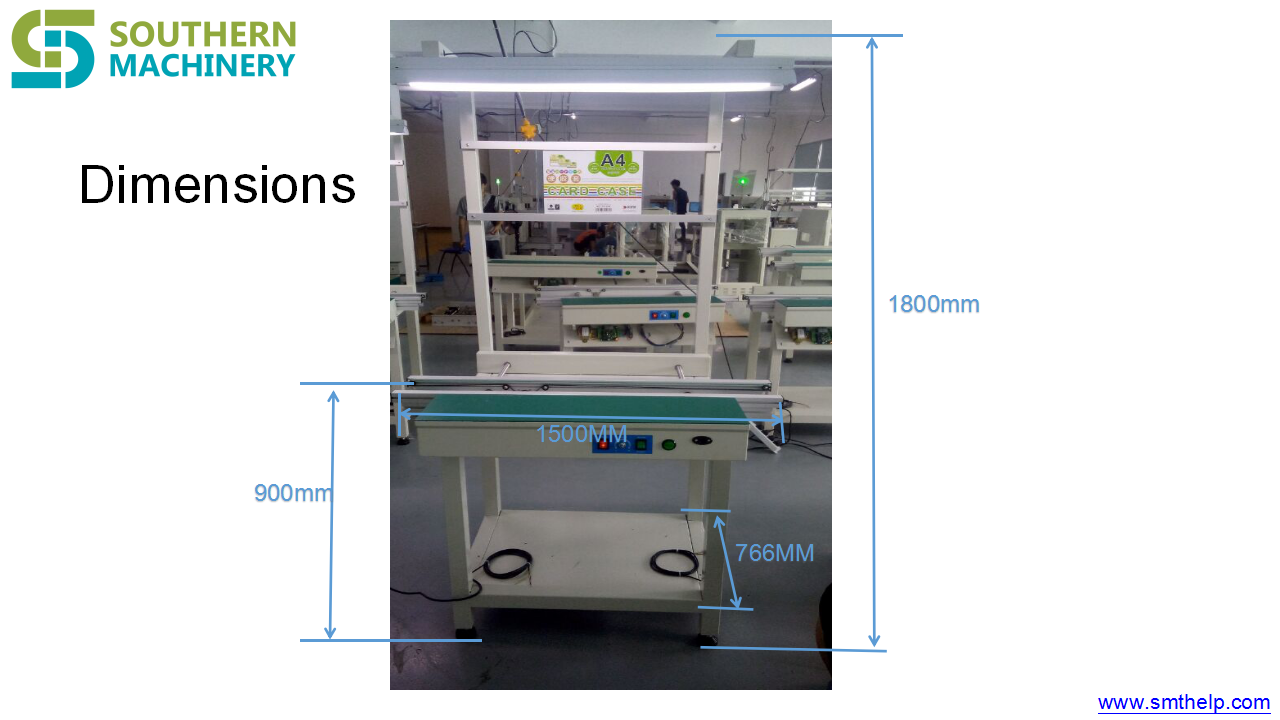
| Conveyor height:750±50mm |
| Conveyor speed:0~1.8M?Min |
| Conveyor Angle:3~7º (adjustable) |
| Conveyor direction:L->R |
| Component heigh :Max.100mm |
| Pre-heating zone:600mm |
| Solder pot wave:2 |
| Pre-heating power:3kw |
| Pre-heating zone temp:room temperature–250°C |
| Cooling zone:1 Fan cooling |
| Solder pot power:6kw |
| Solder pot capacity:Approx.200KG |
| Solder pot temperature:room temperature–300°C±1-2? |
| Control method:P.I.D+SSR |
| System Control:PLC + Touch Screen Control |
| Flux capacity:Max5?2L |
| Spray Fluxer:ST-6 Spray |
| Power Supply:3P 380V AC |
| Total Power:max.9kw |
| Normal working power:Approx.1.5kw |
| Air Pressure:4~7KG/CM2 |
| Dimensions:L2460×W1200×H1650MM |
Weight?Approx.600KG
Chapter 3 Wave soldering start-up instructions
3.1 The boot step of wave soldering
a) Confirm that the machine is connected to three-phase ac380v, 5- line power supply and ensure the machine is grounded properly.
b) Open the total air switch and the switch in the electric control box, then open the power switch on the operator panel.
c) The machine Time control switch is lit, at this time presses the manual / The automatic switch icon, the time control switch displays On state, touch screen lit
d) Touch ( enter ) the button until you enter the operating interface, please refer to the instructions.
3.2 time-controlled switch operation instructions

Instructions for use (Time controller is not used for a long time, every three months need to charge once, the charge times <12 hours)
1. first use, or long time after use, when the controller is not displayed, please after the power, with small items in the lower left corner of the hole open.
2. when powered on, the timer is 24-hour system, please hold the “clock” key for 5 seconds, the monitor will display AMin the upper left corner, indicating that it has been the hour system. Press 5 seconds and return to the hour system, at which time AM display is turned off.
(12 hours When AM is the morning, PM means the afternoon)
3. Set switch time: (if the set opening and closing time is the same, the time controller relay suction for a second ) set steps:
| Steps |
Keys |
Set up a project |
| 1 |
Press (SET) (??) |
Enter timed setting (show 1 on) |
| 2 |
Press (Week) (??) |
set every day the same, or week 1-5 the same, week Six Sunday the same, or daily different (if the same daily, you can not press this key, this time does not show the week, while correcting the clock also No need to press this key) |
| 3 |
Press (time) (?)(? ) |
Set Time to open |
| 4 |
Press(SET) (??) |
Enter the timer setting (show 1 off) |
| 5 |
Press (time) (? )(? ) |
Time to set off |
| 6 |
Press |
If the date of the set off is the same as open, you may not press this key |
| 7 |
Repeat 2-6 steps |
Set the 2-8 times switch time |
| 8 |
Press(clock) (??) |
End Time setting |
* If you do not need 8 switch timing, press (clock) key can be into the clock correction.
* If set error or cancel set this press (clear)(??) key, and then restore the original settings once again
* Display without setting (–:–)
4. Clock Correction:
4.1 Press Live (Clock ) and repeatedly press (week ) to the same day. ( if the daily set switch time is the same, can not press this key, direct correction time, points)
|
|
|
MO |
TU |
WE |
TH |
FR |
Sa |
Su |
|
Monday |
Tuesday |
Wednesday |
Thursday |
Friday |
Saturday |
Sunday |
4.2 Press and hold (the clock) and adjust the time by (time) or (minutes).
5. when you have completed the above operation, press The Open/ Auto/ off ” key, be sure to base your current time on the set of self
controls the time switch, causes the monitor the most downlink to display as (on / off ) or at off(auto / off)
| Explicit shows |
Said |
| On at |
Indicates that the timer is in automatic control and in the open state |
| At off |
Indicates that the timer is in automatic control and is off state |
| On |
Indicates that the contact is in a connected state but the timer does not switch on the set switch time |
| Off |
Indicates that the switch time is invalid in the long shutdown state. |
6. check: Press (set) key to check whether the time set is correct.
7. Modify : please press (clear ) The key at the setting , then reset the time and week of the timing switch.
8. End check: Press (clock) to finish checking and setting, display clock.
9. Manual control: Press (ON/off/off) key, can realize random switch
Attention matters
1. Open The setting of time, can not cross set, should be set according to the order of time.
2. Implement timing Switch Control system Time to set the state in the auto , that is, show on / off (on) or from Move / Close ( at off).
3. The use of the environment should be in line with the environmental requirements of the controller, to avoid vibration, shock, corrosion, dust, electrostatic, high-temperature, high-temperature, direct sunlight environment to use.
4. Please store it in the rated voltage and temperature and humidity condition.
5. maximum current refers to the maximum current when resistive load, lamp current = rated current x20%, motor current = rated power Flow x30%, please use in the specified voltage and current range, if exceed the specified capacity, please contact the AC contactor.
Chapter 4 Interface Operation
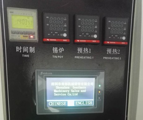 4.1 when the machine electric source button is opened , touch the screen into the Welcome interface ( figure 1 ), waiting about Ten seconds, after the completion of the PLC , the machine automatically open tin furnace heating function.
Figure 1 Startup initial interface
4. 2 Click to touch the screen into the Secretary to introduce the painting surface, such as ( figure 2) Click into the system

Figure 2 Company Introduction
4. 3 Click into the system , touch the screen into the machine to manipulate.the painting surface , as 3.
This painting surface controls all the operation of the machine,
including the manual mode and the self – moving die style.
4.3.1 : Manual mode: Touch screen left upper corner display manual (click to Automatic), manual mode, click Transport, open the chain claw
transport function; Click Preheat, turn on preheat function (must turn on transport to turn on preheating); Preheat temperature to reach, click on the peak, according to the actual product to open the crest, unicast or double wave (long leg wave soldering only a valid), generally only in the back of the red glue patch components need to open the double wave, at this time the peak has been running , the technical personnel can adjust the crest height according to the actual situation; Click on the spray, click the spraying, spray has been working, at this time can adjust the spray size, close to spray, the spray becomes automatic state.
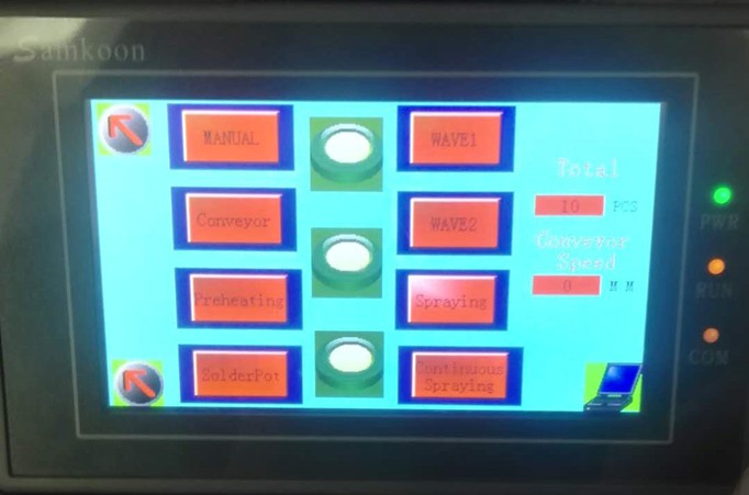
4.3.2 : Automatic mode: Click on the touch screen in the upper left hand corner of the manual switch to Automatic mode, point Open Transport, preheating, as needed to open the crest, spray fog. In the manual mode after adjusting the machine state, at this time the machine can be normal production, when the circuit board into the machine, machine automatic spray, automatic spray, automatic wave soldering.
Fig . 3 machine operator interface
4. 4 Click on the machine in the lower right corner of the EEG map , the machine into the set interface , as shown in Figure four , this screen is used to set the machine‘s shipping parameters.
Spray Distance: This parameter sets the automatic spray time when PCB The board is
transported to the top of the sprinkler start spray, recommended set value to 7 , if PCB
The office has not reached the top of the nozzle has been opened Start Spray, then change
this parameter large, conversely, if PCB after the board is over the nozzle before
beginning to spray, then the parameter is adjusted small;
Spray coefficient: This parameter is not set;
Wave Distance: This parameter is automatic Qipo parameter, when the PCB board is
transported to the front of the tin Furnace, automatic Qipo, this parameter and spray
distance set the same way;PCB board in distance tin furnace 20cm
The peak effect is the best when it is opened.
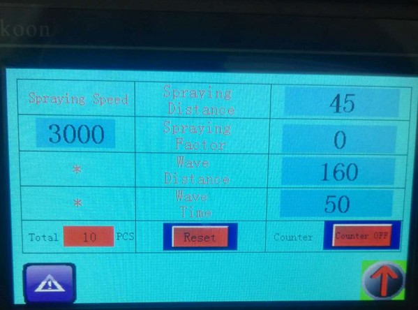 Wave time: This parameter is the peak after the automatic start of the operation time, it is recommended to set the 50-80.
Figure 4 parameter setting screen
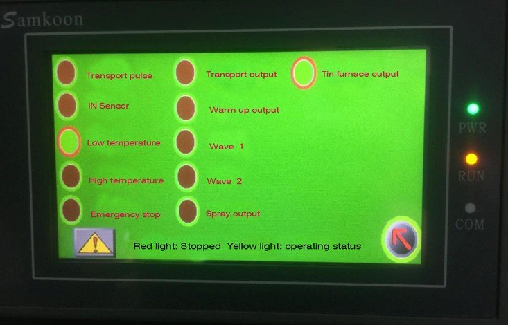 4. 5 Click Control Screen left -pointing arrow chart , into the machine– like monitoring Screen , this screen is used to monitor the operation Status of PLC .
Fig . 5 The status monitor drawing surface
Chapter 5 Installation Adjustment and Commissioning
5.1 Machine Adjustment
After the machine positioning, the level adjustment, first the Foot Cup, so that the rubber wheel off the ground water leveling ruler on the machine to adjust, must make it in a horizontal state.
Adjustment of rail height
(Note: Tin furnace before shaking out, the first tin furnace trolley and rack fixed connection code loosened, and then the tin furnace height lowered, so that the tin furnace nozzle and titanium Claw in the height of a certain gap to avoid damage collision.) The tin furnace can be smoothly shaken out. Note: The foot wave soldering furnace to disconnect the titanium claw first
5.2 Adjustment of Plate feeder
Installation of the machine to install the first access to the plate feeder, the board will be connected with screws fixed, with two
PCB Board to adjust the docking plate, a piece of PCB into the titanium claw inside clamping, a PCB board placed in the plate feeder, two PCB board docking up, By adjusting the plate to the side of the four screw wire To adjust the height of the board connection, so that the two PCB board height parallel, through the adjustment of the machine, such as plate connected to the side of the rice screws to adjust the parallel to the plate feeder and titanium Claw, two fast PCB The joint of the plate butt is completely kissed so that the plate feeder has been installed and adjusted.
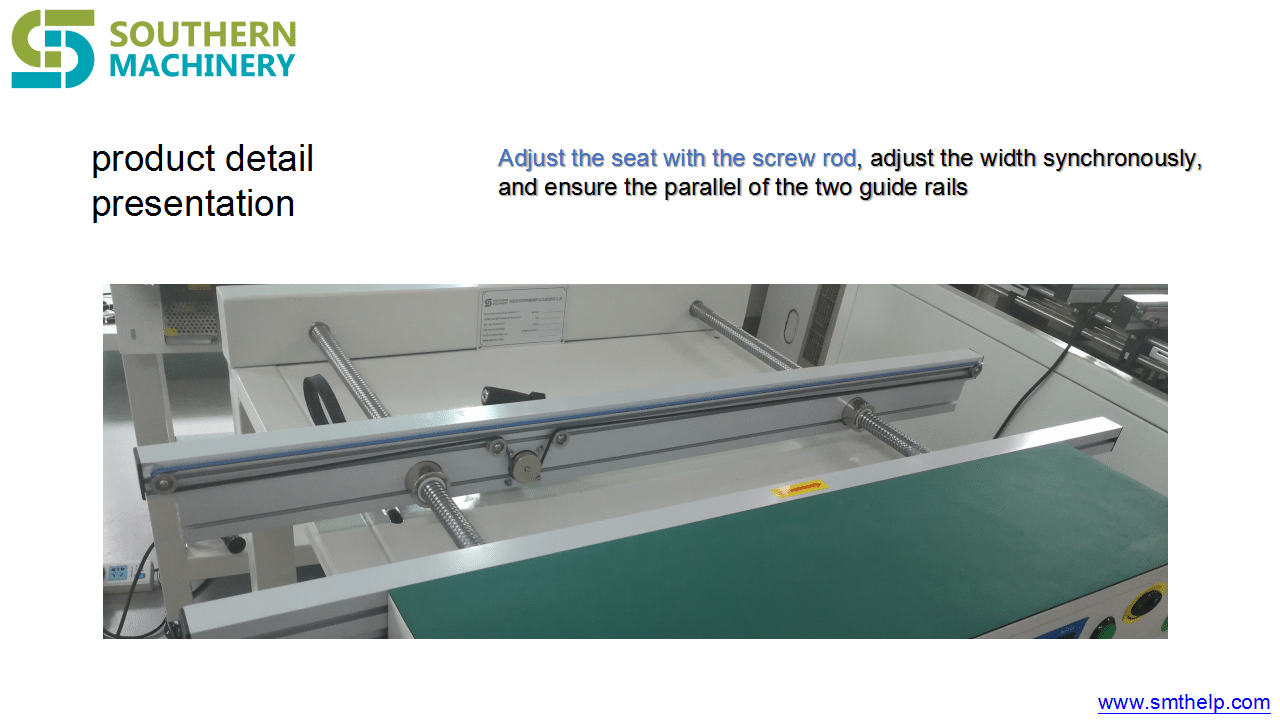
Adjustment of 5.2 guideway width
The width of the guide rail can be adjusted according to the different width of the printed board, the printed board Pinto on the Import board, and the printed board side to the fixed edge of the import plate, the rotation width adjustment handwheel to the printed circuit board can be placed on the guide, and can be moderately pushed to the conveyor chain claw mechanism
Attention:
1. Can not hold too tight or loose, too tight will cause the chain claw and plate deformation; Taisong may appear drop board or PCB side stop affect the quality of welding.
2. before adjusting the width of the chain to check whether the two sides of the solder furnace nozzle plate, if you can touch, it is necessary to increase the guide or reduce the tin furnace, so that the chain claw higher than tin furnace spout Guide.
5.2 Adjustment of Tin Furnace
The height adjustment of the tin furnace can be completed by the tin Furnace trolley lift, and the height standard is approximately 6mm~8mmfrom the top edge of the nozzle by the base board component foot.
5.3 Conditioning of preheating box
The position of the preheating box is fixed before leaving the factory, and can not be easily changed, the preheating box should ensure the bottom
The temperature of the face is between the 80?-180?.
5.4 adjustment of flux spray height
The spray height adjustment is done by adjusting the nozzle height and adjusting the appropriate air pressure and gas.
Loosen the screw that the nozzle is connected with the shaft, the nozzle can be moved up and down, and appropriate adjustments can be made according to the actual needs.
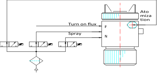 5.5 Nozzle Air Connection mode
5.6 adjustment of the flow of wash claw liquid
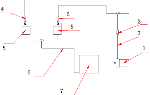 * The adjustment of the volume of wash claw liquid. (see chart below)
|
1.-Alcohol Pump |
2.-Output Pipeline | 3.-Control Valve |
4.- Chain Claw |
|
5.-Wash Claw |
6.-Reflux Pipeline | 7.-Alcohol Box |
The claw pump has a switch control in the touch screen and requires alcohol in the alcohol box and turns on the drive Chain to open
Claw Washer is to ensure that the chain claw clean, to achieve solder quality one of the factors. The device uses a loop-back -flow design, the chain claw through the alcohol moist brush cleaning, flow through the control valve. The capacity of the alcohol box should be Paute 2/3 or more, otherwise the pump will burn, every two days will wash the claw box out of the tin slag clean.
Note: Do not turn the adjustment switch too large and the alcohol overflow machine, so as not to cause a fire.
5.7 Commissioning
after the equipment is installed, the equipment should be fully checked, and after the system and mechanism are working normally, then put into normal use.
* Prepare Equipment
flux approx . 20L
Cleaning Lotion about 12L
Solder lead -free solder 400kg
Electric Stove 3Kw 1
Stainless steel tank 1
* Molten Tin
The solid solder is poured into the stainless steel container in batches, heated to the furnace to fully melt ( about the? ), and then poured into the tin tank of the equipment, when the solder liquid surface is about 8mm from the tin Groove mouth , Stop feeding start-up equipment, the tin furnace temperature preset for 245?, to tin furnace temperature, start the crest, adjust the crest height, check whether the crest is normal. Josi surface is low, at this time can be the bar-shaped solder directly into the tin furnace, adjust the tin surface to fit. Note:a. Tin Tank for the first time, the Solid Tin Bar ( block ) material directly into the tin furnace to melt, In case a large amount of heat can not be passed to the solid solder in time, resulting in high-temperature burning tin trough and heating pipe. b. Before dissolving the tin, the tin trough and the stainless steel container should be cleaned to prevent the impurity from polluting the solder.
* Check Flux Spray Condition
The flux is injected into the rosin groove, connected to the gas source and activated. “Spray Fog ” , check whether the spray is normal. the proportion of flux in accordance with the requirements of manufacturers and actual use of the situation, can be 0.80~0.87 within the scope of appropriate adjustments. ( manufacturers are best to provide free cleaning flux)
* Other
Check the transmission, adjust the body is normal, respectively, start the transport, washing claws, cooling, preheating and so on, check is normal, commissioning completed.
Chapter 6 Inverter Description
(See VFD-M Manual and temperature control sheet , This manual is presented in conjunction with the instructions )
Chapter 7 Spray Type Rosin Furnace
7.1 composition of rosin furnace
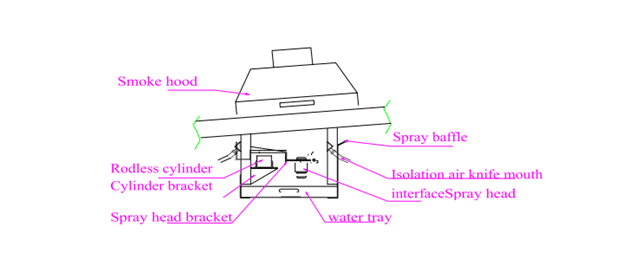
Rosin furnace is made of stainless steel, sealed containers, flux stored in this will not evaporate and absorb moisture in the air, and maintain a stable solvent composition, and with high-precision import nozzle and Germany or the United States rod-free cylinder, imported light eye, is currently the most ideal welding equipment users. The structure is shown in the figure below.

7.2 correct use of rosin furnace
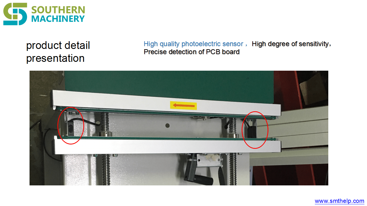
the height of the rosin spray can be adjusted (see spray height adjustment), can also adjust the solenoid valve on the airflow regulator or pressure regulator on the air conditioner, the factory has been adjusted so easy to change, to avoid making into the spray system chaos, when working when the substrate through the input photoelectric tube, time control system started, and began to delay spraying and spraying tin until the substrate through the rosin furnace 3-5 seconds to stop spraying.
Note: The flux must be clean-free dapoxetine type, which is characterized by the plate surface after welding without ultrasonic cleaning, clean and beautiful board.
7.3 instructions for the use of nozzles
I, the safe operation of the case of special attention to the following matters:
7.3.1. Take appropriate precautions before use to prevent injury to the human body or damage to the product.
7.3.2. Do not point an open flame or close to an open fire place, to avoid static electricity.
7.3.3. In the installation or maintenance process should be all fittings with raw tape, such as the connection slack, in the gas
Under the pressure of the body, various liquids will be sprayed into the body.
7.3.4. When connecting the air pipe and the solvent pipe, please select different material and pay attention to the pressure of the hose can not exceed the regulation, do not use the damaged old trachea.
7.3.5. Often clean the nozzle on the solvent, the residue on the road, may cause trouble, is in the direction of people can not press the switch.
II. Methods of Use
1. Install despotism M10 stainless steel screws tighten.
2. When installing trachea and solvent fittings, please seal with raw tape, no leakage.
3 . The standard jet pressure is 0. – MPa, standard distance 200-0 mm.
4. Adjust the valve nut ( vent quantity ).
5 . on the nozzle labeled ” F “Then solvent Pipe interface,”N” “C” to connect the air pipe. “N” is a jet input pipe interface.
III. Maintenance and Repair
1. After each class work completes promptly cleans the nozzle the superfluous residue agent.
2 . use a brush or toothbrush when cleaning. (be careful not to damage the gas cap and nozzle “O” rings.)
3. Periodically add grease to the “O” ring to add lubricating oil to the needle clamp. Take care not to tap the needle when removing the clip.
Fault Handling table
| Symptoms |
Possible causes |
Handling countermeasures |
Solvent Breakpoint
1. Insufficient amount of solvent
2. Liquid tube Hardening is blocked
3. Nozzle slack or damaged
4. Needle Clamp Fixed nut loose
1. Supplemental solvents
2. Replacement of liquid Tube
3. Tighten or replace
4. Tighten or replace the needle clip
Side Type Spray shape
1. blockage or damage of valve vent empty silo
2. The nozzle has a dirty glue
1. Clean or replace
2. Clean or replace
The spray shape is Crescent type
1. Valve vent empty bin obstruction or damage to the internal wall of the valve adhesion solvent slag valve center hole damage
2. The nozzle has the dirty material adhesion or the nozzle damage
Cleaning or replacement
The spray shape is thick type
1. Valve Center hole too large
2. Low Injection pressure
3. High solvent concentration and high pressure
1. Replacement
2. To adjust the high bias pressure
3. Diluted solvents ,Reduce driving pressure
The spray shape is narrow
1. air pressure is too high
2. slag between valve and nozzle
3 Reduce air pressure
4 Cleaning
7.4 Daily maintenance and precautions
7.4.1. after Regular cleaning nozzle to ensure smooth nozzle.
7.4.2. always keep the liner slide clean and lubricated, no solvent immersion, so as not to affect the rod the normal use of cylinders.
Chapter 8 Preheater
8.1 the role of Preheater
The role of preheater is to increase the expansion rate on solder pads by preheating the flux activation and
To promote the evaporation of the PCB flux solvent, thus obtaining the best soldering effect. In addition, the circuit board after preheating, reduce the PCB and tin furnace temperature difference, to avoid the thermal impact of electronic components and circuit board sudden thermal deformation.
the optimum temperature for preheating is 120~180?. The temperature is too high can cause undesirable consequences; too low temperature affects welding quality.
8.2 The construction of preheating box
the preheating system is composed of imported blackbody heating pipe. The Preheating box and the guide rail are connected by screws to facilitate the inspection and maintenance of the line.
The best preheating temperature on the circuit board is 120-180 ?, the temperature of the preheating box is passed by the high accuracy temperature probe to the preheating electronic thermostat to adjust, can accurately control the preheating box temperature, protect the circuit board, achieve the most ideal preheating effect.
8.3 Daily Maintenance and Precautions
8.3.1 The temperature of the circuit board’s bottom surface is often tested to ensure that 120~180? between the two to ensure the best solder effect.
8.3.2. Check whether the circuit wire aging, in order to prevent current interruption.
8.3.3. Clear the flux residue in the drawer of preheating box, lest the set will cause fire.
Chapter 9 Tin Furnace
Tin furnace structure using stainless steel production. By the wave generator, nozzle filter, impeller, motor and other groups
Yes. The use of pump-type principle to form a crest.
Tin furnace structure is reasonable, high technical content, the use of Japanese and American tin Furnace advantages of the development of high standard tin furnace. Its characteristics:
1 reduce the tin oxidation to a minimum.
2 nozzle wave smooth, tin surface can be adjusted vertically to adapt to different PCB board welding requirements,
3) External heating effectively avoids the phenomenon of explosion tin, good insulation performance, tin furnace durability does not deform.
4) long service life.
Tin furnace body is by corrosion-resistant stainless steel plate welding into, heating tube installed in the tin furnace two outside. Use
Alloy
Plate to radiate heat, so that the temperature uniformity of the tin furnace, the overall heat balance does not deform, spray cavity set up without clogging nets,
Can keep the peak smooth and smooth, and not plug, thus reducing maintenance, improve efficiency.
9.2 correct use of tin furnace
Tin Furnace high and low and in and out of the mobile can be used to set up the joint hand wheel and lifting screw adjustment , adjust the tin Furnace crest can be adjusted by the frequency converter, the higher the impeller speed, tin furnace crest is higher;
Solder temperature controlled by the thermocouple in the tin Furnace. First of all, the expected solder temperature set, usually the normal solder temperature is 230-250 ?.
In the back of the tin furnace with a row of tin Tsui, used to clear the tin furnace. The tin furnace to the back of the removal, cleaning and maintenance, before the tin furnace removed, must first be the guide rail high or tin furnace to reduce a certain height to avoid the rail chain claw and tin furnace collision caused by the chain claw deformation.
In the demolition of the furnace, referring to the structure shown above, the nozzle removed first, the motor frame and impeller out, loosen the furnace liner fastening bolts, you can remove the furnace.
9.3 Daily maintenance and precautions
9.3.1. Regularly check the amount of tin to control the “spray tin wave.”
9.3.2 . measure soldering temperature with mercury thermometer ( standard temperature0?). If the preset solder temperature is unstable , it can be adjusted in the temperature control table.
9.3.3. Depending on the resulting oxide, add antioxidant grease. (Anti-oxidation grease and flux supporting use)
9.3.4. Frequently remove oxides from tin furnaces.
9.3.5. Check the tin furnace motor coupling on the machine rice and impeller shaft coupling machine meter and its operation, to ensure its normal operation.
9.3.6. Pay attention to check the wire has no aging, as well as the parts of the screws, nuts are loose.
9.3.7. Spray nozzle every day after work with alcohol automatic cleaning, lest block.
Chapter 10 Maintenance and precautions
1. Often the fuselage, transport, claw pump, cooling fan, such as motor housing cleaning to facilitate the cooling and insulation.
2. Regular inspection of electrical control box in the electrical appliances and fastening the screws on its terminals, such as the discovery of contact ablation, suction and not flexible, etc., should be dealt with in a timely manner.
3. Regular inspection of preheater, tin furnace heating pipe joints, such as the discovery of head loosening, poor contact, insulation aging and other phenomena should be tightened, clean and replace.
4. Regular inspection of equipment to protect the grounding device is good.
5. In the operation of the equipment, pay attention to monitor the shell temperature of each motor, overheating phenomenon should be stopped check.
6. When the general switch on the power supply, should first stop the tin Furnace, preheating and wave crest and other large current load before entering
Yes.
7. After the main power switch trip, you must find out the cause of the failure, before the closing.
8. In the process of melting solder and injecting high temperature liquid solder into the welding furnace, wear protective articles to prevent
Scald.
9. Flux, Wash claw liquid are flammable materials, use should pay attention to fire safety.
Ten after working every day, you need to clear the flux residues in the preheater to prevent accumulation. cause an open flame.
11. The limiter can not be added lubricating oil, so as to avoid the transmission chain claw not go.
12. Anti-oxidation wax (oil) should be used with flux to avoid fire.
13. Each transmission part should maintain the good lubrication, except the angle adjustment mechanism may use the ordinary ointment, other all uses the High-temperature ointment lubrication.
14. The tightness of each transmission chain should be checked and adjusted regularly.
15. Regular inspection of tin furnace speed motor lubrication and operation, to ensure its normal operation.
– Tin furnace Nozzle should be based on the peak stability, the peak when the exception to clean the nozzle, so as not to affect welding quality.
18. Spray nozzle should always check the tightness of its connection.
Chapter 11 Wiring
This equipment needs external 3? , ac380v,50HZ power supply ( three-phase five wire system ), power supply capacity
The quantity is not less than 20KVA, the equipment shell should protect the grounding, the grounding resistance ?4?, the grounding conductor is not less than
4mm2, the incoming line should be no less than 6mm2?
Chapter 12 General Trouble shooting
To ensure high quality, the devices used in the equipment are advanced industrial countries of high-quality products, such as million
In the event of an accident, please check each of the items listed in one table. If you are still unable to resolve, please contact the company directly.
| Failure phenomenon |
Reason |
Check processing |
All action buttons are invalid
1. Time is not in the state of timing
2. The tin temperature is not up to the set value
1. Set the scheduled boot time before the current time.
2. Wait until the temperature of the tin furnace, then operation.
Control power LED not lit
1. Power supply Missing phase
2. Fuse on the bottom plate of the electric vessel
1. Overhaul power supply.
2. Check whether there is a short-circuit phenomenon in the lights, etc.
In addition to the failure, replace the new insurance pipe (4A).
Power supply Total Switch tripping
1. Load and line occurrence short-circuit phenomenon
2. Power supply Total Switch Contact bad
1. Check the load and related lines, troubleshooting short-circuit.
2 . Check the wiring area of the power supply master switch for appearance loosening, heating, oxidation and whether the switch contact point is out contact is bad, ablation and other phenomena, or to be seized
repaired or replaced.
Tin Furnace or preheating
Slow warming of the device
1. Power supply is too low
2. Additional Hotline ( tube )partially damaged
1. Improve the quality of power supply.
2. Replace the hotline ( tube ) .
Transport Claw not running
1. Transport motor shaft end of the drive chain skid, Force nut Loose
2. chain speed set to “0”
3.fx-2da or inverter damage
1. Fixed nut for fastening drive sprocket.
2. chain speed set to not “0” position.
3. fx-2da or inverter.
Failure and solder welding problem analysis
| Fault |
Possible causes |
Press the button to press , But the LEDs are not lit
1. Total switch not open, emergency stop switch not open
2. LED light bulb failed
3. Total switch failure
Press the button to press, but the machine does not run
1. Total Switch not open
2. Press-twist failure
3. Relay failure
When the Rosin furnace is bad
1. The pressure of the rosin furnace is too low
Uneven Rosin Coating
1. The nozzle is damaged
2 . Water, obstruction of trachea
3 . The density of the rosin liquid is too dense
4. Air pressure is too low
5. Pressure regulator failure
Preheater temperature too high and too low or preheater
1. Voltage is too high or too low
Bad use
2. Heating line burnt or terminal loose.
3. Temperature probe Abnormal
4. Temperature control Failure
Tin furnace can not maintain enough tin crest
1 . The nozzle has been blocked
2 . Coupling loosening
3. Impeller Wear
4. Motor Transport Instability
5. Tin solder is impure, especially when the zinc content is larger than the specified value
6. The furnace temperature is too high
Welding problems and Treatment methods
|
Solder state after soldering |
Original for |
Branch Square Law |
Welding is not good
1. Surface oxidation of copper foil pollution
2. Flux preheating is not enough
3. Too little Flux
4. Low solder temperature
5. Conveyor belt speed
6. PCB in the tin solution leaching excessive
7. Copper foil area is too wide
8. Wuxi Protective Film
9. Flux and molten solder do not melt
Clean copper foil and component ends; PCB, components for long-term storage, research flux is no problem, for new flux.
Out of the tin pillar
1. Copper foil surface, component ends of oxidation and pollution
2. Solder welding of flux is not good
3 . The chemical changes of the coating flux and copper foil 4. Flux metamorphism
Clean copper foil surface, fully preheat, Preheat temperature standard: Aldehyde circuit board to
– ?, epoxy circuit board 120 to?
(Solder surface temperatureadjustment flux, eutectic solder , temperature for250~260? circuit board and tin liquid contact do not exceed the road plate thickness of the 1/2. Reduce the height of the tin liquid to adjust the speed of transmission , research circuit board design, in
Circuit board coating Protective film.
The occurrence of the lap
1. Copper foil surface, component ends of the oxidation of pollution
2. PCB Solder direction is not good
3. PCB design is not good
4. No Solder protection film
Cleaning the copper foil and the side of the side of the oxidation of dirt, change the direction of the circuit board solder, coating Tin protective film, the study of circuit board set
Millions
No tin on the ends
1. Oxidation of the dirt on the ends
2. There are things that do not touch tin (e.g. paint, organic resin)
3. Solder welding of flux is good
4. Flux time too long quality deterioration
Clean copper foil and the end of the surface, do not hang tin, with the pump to remove the attached oxide, dip welding do not exceed the thickness of the PCB 1/2
Virtual Welding Baken Bubble
1. Solder temperature is too low
2. Solder welding of flux is not good (low ratio of flux)
3. Oxidation of the dirt on the ends
4. Surface oxidation of copper foil pollution
5. Flux deterioration
6. Conveyor belt speed too fast
7. Wuxi Welding Protective Film
8. The circuit board damp produces the bubble
solder welding temperature is defined as 250~260? Inspection Welding Agent to remove the ends of the oxide adjustment parts of the ends line Diameters (D) and Aperture d ( e.g.
d=1.d=0.8 conveyor belt speed of one meter per minute, the circuit board in advance drying.
Some places do not touch tin
1. A part of copper foil surface pollution
2. Sipo and PCB contact but do not hang tin
3. PCB Bending
Clean the ends of the line (stripping or welding again) to avoid long-term storage, check the flux or change the new
Flux.
PCB Bending
1. Solder temperature is too high, preheating temperature
2. Conveyor belt speed is too slow
3. PCB does not press well
Solder Solder temperature is 250~260?, transfer with speed set to standard one metre per minute, line
The corners of the road plate are pressed tightly.
Chapter 13 Appendix
Appendix I: Selection of welding process parameters
The selection of welding process parameters has been described in the relevant chapters for easy access to the present list as follows:
| Choose |
Process parameters |
Select Range |
Notes |
| 1. |
Tin Furnace Temperature |
230~260? |
245 ? is generally optional |
| 2. |
Preheating temperature |
80~180? |
PCB welded surface after preheating should reach the single panel 90 ?, double-sided Board 110 ? |
| 3. |
Transport speed |
0~1.9m/min |
Generally optional for 1.2 m/min |
|
4. |
Flux proportion |
0.80~0.87 |
According to the technical requirements of the flux manufacturer and the actual welding situation Adjustment |
| 5. |
Crest Height |
Press at 1/2~2/3s |
Thickness of s= printed circuit board |
Appendix II: Technical parameters of lead-free solder
Name |
Alloy Composition (wt%) |
Melting temperature (?) Solid state line/liquid Line |
|
| M – Series Solid state temperature 200~250? | |||
| M31 |
Sn-3.5ag-0.75cu |
217 |
219 |
| SA2515 |
Sn-2.5ag-1.0bi-0.5cu |
214 |
221 |
| M41 |
Sn-2.0ag-0.5cu-2.0bi |
211 |
221 |
| M42 |
Sn-2.0ag-0.75cu-3.0bi |
207 |
218 |
| M702 |
Sn-3.0ag-0.7cu |
217 |
219 |
| M704 |
Sn-3.35ag-0.7cu-0.3sb |
218 |
220 |
| M705 |
Sn-3.0ag-0.5cu |
217 |
220 |


 The main characteristic of S-6000 is small volume, Mounting very fast, high precision when it works, simple operation, stable running and competitive price. Not only can help you to avoid the mounting instability by man-made, but also can help you to solve the problem like high labor cost, high site cost, low production efficiency, and so on. Our product can greatly improve the