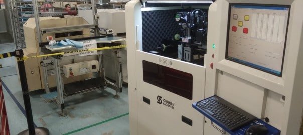
Automatic desktop SMT
pick and place machine
Model: S-6000V
Catalog
-
Import Material Order
- Import the coordinate file
- Material stack configuration function
-
Mounting Setting
- Mount setting function and introduction
-
Puzzle Setting
- Program Runs

SMT system programming tutorial
-
Import Material Order
-
Import the coordinate file
Import PCB file coordinates directly and scraping PCB components coordinates manual.
① PCB coordinate document template, it is the CSV file.
 ②Open control system main interface – > file – > new file – > import coordinate.
③ The CSV file, PCB general has Top layer and Bottom layer element coordinates, please confirm the current PCB is the top layer or the bottom layer, choose in the lower left corner coordinates. Then click the lower right corner → the import button.
Import the coordinate file function instructions:
|
Import the coordinate file function instructions
|
|
Option name
|
Operation
|
instructions
|
|
Coordinate
surface
|
|
Choose the Top layer and Bottom layer to import coordinate
components.
|
|
Flip coordinate
|
|
Select this option, will perform PCB flip horizontal coordinates
|
Flip Angle
|
Option
|
|
|
Allow Blank
|
When coordinate file have the margin, import coordinate indicates a blank space, must be made to modify the file and then import, avoid programming error.
Select this option, will ignore the coordinate file integrity, errors
may result in mounting components.
|

-
Grab the coordinate file by hand
|
X Y positioning equipment function
|
|
Option name
|
Operation
|
function
|
|
drop-down
|
|
|
|
options
|
Option
|
Choose the cursor, nozzle 1, nozzle 2 to grab positioning tool of the coordinate.
|
|
Open cursor
|
|
Close cursor
|
|
Back to Home
|
Execute
|
Machine return to original state
|
② Stepping set and X Y movement Function
|
Stepping set and X Y movement Function
|
|
Option name
|
Operation
|
Function
|
|
Stepping set
|
Option
|
Alternatively the step size of the X Y directions
|
|
X Y movement
|
Execute
|
Up and Down, Leaf and Right button could Operate X Y direction positioning, In operation, please don’t close to the machine tool
|
③ Manual input coordinate function
| Manual input coordinate function |
| Option name |
Operation
|
Function
|
| Bit No. |
Modify
|
General is number, To manager the PCB program more
clearly, fill the PCB current anchor element bit number.
|
| Component Package |
Fill the PCB current anchor element component package.
|
| Center X |
Automatic acquisition
|
Operation the movement direction key to the PCB component packaging center, Automatically obtain X Y
coordinate value, please do not modified by hand.
|
| Center Y |
| Angle |
Modify
|
Angle of PCB component
|
| Component Type |
Type of PCB component
|
|
Note: After setting the above operation,, click “OK” to record coordinate current bit number. And then to do the next one. Directly to the center of the moving direction key to enter a number to setting, Click “OK” to finish record
coordinate current bit number.
|

|
Material stack configuration function
|
|
Option name
|
Coil stock
|
tray stock
|
|
station number
|
According to the material stack number
|
|
Program Component
|
Click and choice of material stack put components corresponding
component model, choose components are not allowed to repeat
|
|
Material System
|
Click into the system of material select stack corresponding packaging material with
configuration
|
|
|
Component
|
Click into the system components and system interface to select material
with the corresponding system components package
|
| Calibration center |
Click on the center coordinate values into the center calibration interface,
moving XY direction calibration feed tray placed in the center of the stack and elements to get set up
|
| Calibration broaching |
Click broaching broaching coordinate values into the calibration interface, moving XY direction calibration broaching
center to get set up
|
|
| Initial angle |
Material stack element display angle, the system default 90 ° degrees
|
Rows , columns line
spacing, column space
|
|
Modify the settings for each display from the ranks of the number and the element array tray
material
|
| Adapter nozzle |
2 head: left one is 1,the right one is 2, according to the different elements
of the package material stack, could change any head.
|
| Flight Speed |
Normal:30000pps, Special components can be customized flight speed.
The smaller data , the slower operating speed
|
|
More materia
l stack
option
(Picture
6)
|
Pick up
speed
|
Refers to the suction nozzle picking up speed, Normal: 20000pps.
The smaller data , the slower pick up speed
|
|
Pick up
Depth
|
Refers to the suction nozzle distance with the end face contact material stack material when pick up the component, Through the calibration can get picked up depth data, Special component separately select pickup
depth
|
|
Pick up
alone
|
To some special material stack, setting the speed the depth separately.
|


- Multi-line batch modification Description
| Multi-line batch modification Description |
Description: Bit column number , hold down the left button to select a number of modifications can
make the following batch modify.
|
| Option Name |
Operation
|
Description
|
| Center X |
Modify
|
batch settings calibration center X coordinate of material stack
|
| Center Y |
batch settings calibration center Y coordinate of material stack
|
Broaching partial
X
|
batch settings Broaching partial X coordinate of material stack
|
Broaching partial
Y
|
batch settings Broaching partial Y coordinate of material stack
|
| Pick up depth |
batch settings pick up depth of material stack
|
| Adapter nozzle |
Option
|
batch settings adapter nozzle of material stack
|

- Material stack debugging tools, data checking function description
| Material stack debugging tools, data checking function description |
| Option Name |
Operation
|
Description
|
| Material stack test |
Execute
|
Pick up test for calibration finished material station configuration
list
|
Save material
station to the file
|
Save the material station file for calibration finished material station configuration list, it could make it easy for the nest use.
|
Loading the material station
from the file
|
Can be loaded directly with the saved material station.
|
| Check no material |
Check the Program Component in the material station
configuration list for no material.
|
Check double
material
|
Check the Program Component in the material station
configuration list for double material.
|
Check nozzle
vacancy
|
|

-
Mounting Setting
- Mount setting function and introduction
 Programming parameters automatically get in after the second material Stack Configuration.


Calibration Function description
-
PCB information – Align programming origin
① Click the Align program into the coordinate system origin correction interface.
② Calibration Make sure whether the splint placed parallel to the PCB in place, subject to the plywood base point, and then calibrate.
③ Calibrating the far two point coordination ( reduce the error), Click OK after finished
 calibrate.
-
Setting Mark point ( This setting must be completed – after operating alignment program origin )
Set Mark Point, choose a more independent square or circular Mark point as calibration points.( (Note: Mark point usage; in the fourth programming due to the PCB board or puzzle on the origin lead to error, click Mark point to automatic correct board )
-
Calibration ( This setting must be completed – after operating alignment program origin )
Calibration is used to correct a separate placement coordinate with the actual Mark-point calibration.

② Check invalid pick up material station, check whether the configuration is complete.
It can horizontal and vertical puzzle PCB.

- Manual correction and automatic correction
-
Puzzle calibration Make sure whether the splint placed parallel to the PCB in place, subject to the plywood base point, and then calibrate.
① Manual correction: Click the PCB list of coordinates to enter the calibration correction, respectively coordinate 2 far point calibration.( reduce the error), If there is the puzzle PCB, then do the first PCB, and send and so no. The same way to calibrate.

 ② Mark point automatic correction: one-time auto-complete according to automatic Mark point on board.

-
Program option function 5.1.1 Function
|
Option Name
|
Operation
|
Description
|
|
Base plate Depth
|
Calibration
|
Nozzle and plywood PCB contact distance, setting through the
calibration.
|
|
Optimization Option
|
|
Option
Dual stepper reel, can improve the placement rate.
Nozzle
The default double election: if canceled a nozzle will not be placement relative programming can not be involved in SMT production process, two nozzles are canceled, the program
can not be generated.

|
Option Name
|
Operation
|
Description
|
Option
Select the test mounting, roll feed zone does not feed tray,
please do not put components, SMT will simulate patch
End the process when
the error occurred
Selected, SMT work when other material stack error will end the current SMT all the work, and stop running
Speed Stalls
Set
The smaller stalls, The slower SMT run speed
Starting line number
It may be the current line number bit number for starting SMT
placement
Back Home
Execute
Back to initial state.
Start
Start SMT run
Pause / Resume
When SMT work, click this button, it could pause, and click
again, it could resume to work.
End
End the current work.

5.3 Mount coordination Preview
 Function: You can preview the imported PCB plots, red for the selected package components , it can zoom right to select the bit number to view the preview package management.